instrument panel Lancia Musa 2009 Owner handbook (in English)
[x] Cancel search | Manufacturer: LANCIA, Model Year: 2009, Model line: Musa, Model: Lancia Musa 2009Pages: 218, PDF Size: 3.7 MB
Page 8 of 218
7
SAFETY
DEVICES
STARTING
AND
DRIVING
WARNING
LIGHTS AND
MESSAGES
IN AN
EMERGENCY
MAINTENANCE
AND CARE
TECHNICALSPECIFICATIONS
INDEX
DASHBOARD
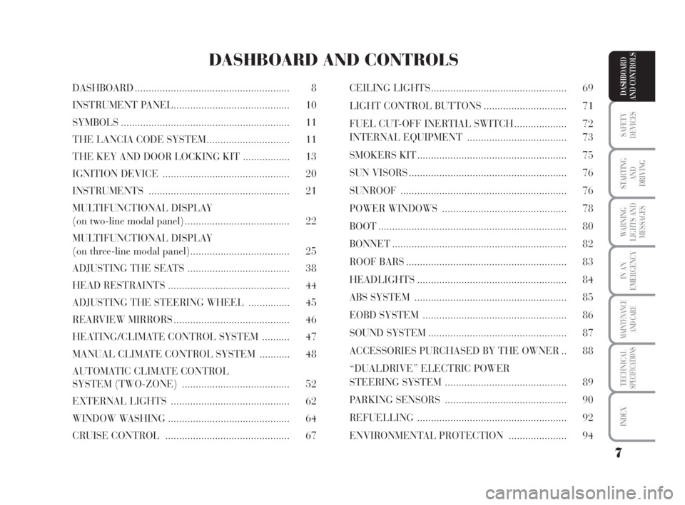
AND CONTROLSDASHBOARD ........................................................ 8
INSTRUMENT PANEL.......................................... 10
SYMBOLS ............................................................. 11
THE LANCIA CODE SYSTEM .............................. 11
THE KEY AND DOOR LOCKING KIT ................. 13
IGNITION DEVICE .............................................. 20
INSTRUMENTS ................................................... 21
MULTIFUNCTIONAL DISPLAY
(on two-line modal panel) ...................................... 22
MULTIFUNCTIONAL DISPLAY
(on three-line modal panel).................................... 25
ADJUSTING THE SEATS ..................................... 38
HEAD RESTRAINTS ............................................ 44
ADJUSTING THE STEERING WHEEL ............... 45
REARVIEW MIRRORS .......................................... 46
HEATING/CLIMATE CONTROL SYSTEM .......... 47
MANUAL CLIMATE CONTROL SYSTEM ........... 48
AUTOMATIC CLIMATE CONTROL
SYSTEM (TWO-ZONE) ....................................... 52
EXTERNAL LIGHTS ........................................... 62
WINDOW WASHING ............................................ 64
CRUISE CONTROL ............................................. 67CEILING LIGHTS ................................................. 69
LIGHT CONTROL BUTTONS .............................. 71
FUEL CUT-OFF INERTIAL SWITCH ................... 72
INTERNAL EQUIPMENT .................................... 73
SMOKERS KIT ...................................................... 75
SUN VISORS ......................................................... 76
SUNROOF ............................................................ 76
POWER WINDOWS ............................................. 78
BOOT .................................................................... 80
BONNET ............................................................... 82
ROOF BARS .......................................................... 83
HEADLIGHTS ...................................................... 84
ABS SYSTEM ....................................................... 85
EOBD SYSTEM .................................................... 86
SOUND SYSTEM .................................................. 87
ACCESSORIES PURCHASED BY THE OWNER .. 88
“DUALDRIVE” ELECTRIC POWER
STEERING SYSTEM ............................................ 89
PARKING SENSORS ............................................ 90
REFUELLING ...................................................... 92
ENVIRONMENTAL PROTECTION ..................... 94
DASHBOARD AND CONTROLS
007-037 MUSA 1ed GB 10-07-2008 9:36 Pagina 7
Page 9 of 218
8
SAFETY
DEVICES
STARTING
AND
DRIVING
WARNING
LIGHTS AND
MESSAGES
IN AN
EMERGENCY
MAINTENANCE
AND CARE
TECHNICALSPECIFICATIONS
INDEX
DASHBOARD
AND CONTROLS
L0D0374m
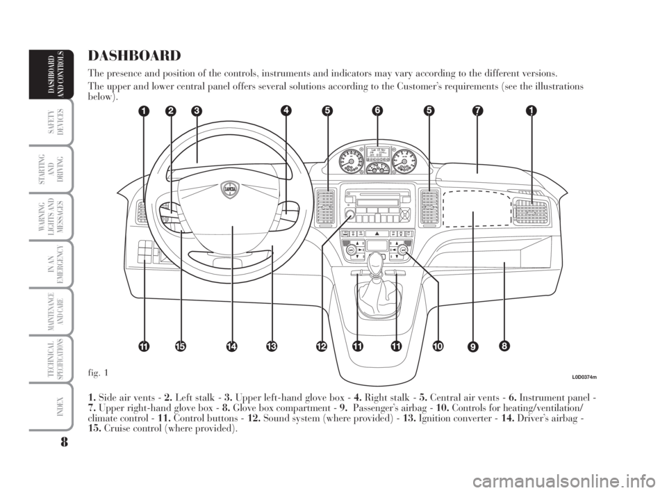
1.Side air vents - 2.Left stalk - 3.Upper left-hand glove box - 4.Right stalk - 5.Central air vents - 6.Instrument panel -
7.Upper right-hand glove box - 8.Glove box compartment - 9.Passenger’s airbag - 10.Controls for heating/ventilation/
climate control - 11.Control buttons - 12.Sound system (where provided) - 13.Ignition converter - 14.Driver’s airbag -
15.Cruise control (where provided).
DASHBOARD
The presence and position of the controls, instruments and indicators may vary according to the different versions.
The upper and lower central panel offers several solutions according to the Customer’s requirements (see the illustrations
below).
fig. 1
007-037 MUSA 1ed GB 10-07-2008 9:36 Pagina 8
Page 11 of 218
10
SAFETY
DEVICES
STARTING
AND
DRIVING
WARNING
LIGHTS AND
MESSAGES
IN AN
EMERGENCY
MAINTENANCE
AND CARE
TECHNICALSPECIFICATIONS
INDEX
DASHBOARD
AND CONTROLS
L0D0372m
L0D0010m
fig. 7
fig. 8
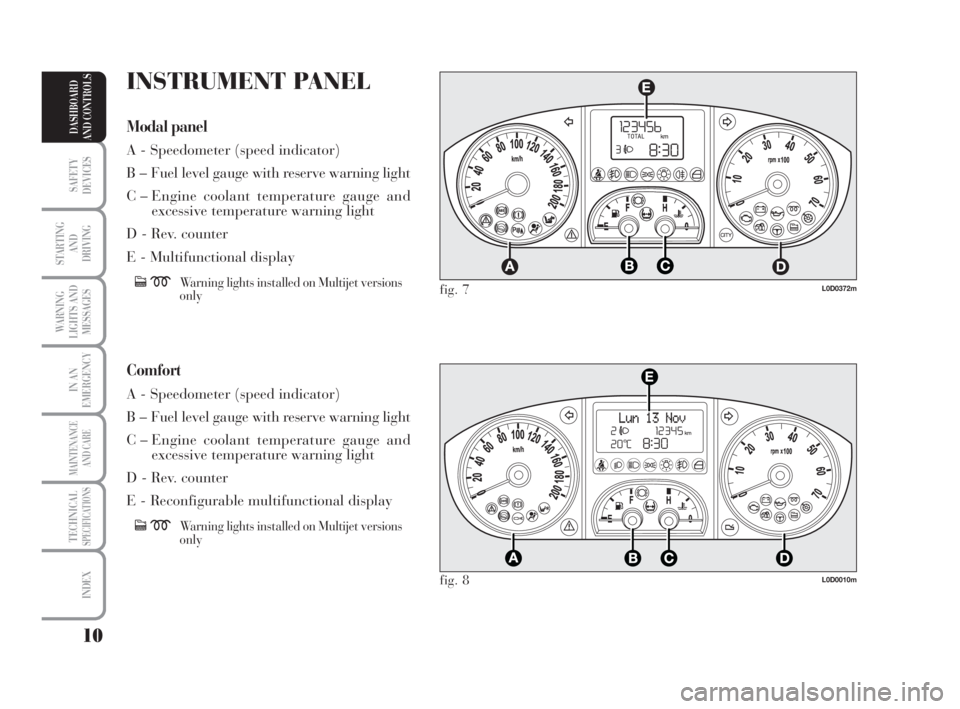
INSTRUMENT PANEL
Modal panel
A - Speedometer (speed indicator)
B – Fuel level gauge with reserve warning light
C – Engine coolant temperature gauge and
excessive temperature warning light
D - Rev. counter
E - Multifunctional display
cmWarning lights installed on Multijet versions
only
Comfort
A - Speedometer (speed indicator)
B – Fuel level gauge with reserve warning light
C – Engine coolant temperature gauge and
excessive temperature warning light
D - Rev. counter
E - Reconfigurable multifunctional display
cmWarning lights installed on Multijet versions
only
007-037 MUSA 1ed GB 10-07-2008 9:36 Pagina 10
Page 13 of 218
12
SAFETY
DEVICES
STARTING
AND
DRIVING
WARNING
LIGHTS AND
MESSAGES
IN AN
EMERGENCY
MAINTENANCE
AND CARE
TECHNICALSPECIFICATIONS
INDEX
DASHBOARD
AND CONTROLS
In this case, turn the key to STOPand
then back to MAR. Try with the other
keys provided if the problem persists.
If the engine will not start up after
this operation contact the Lancia
Dealership.
IMPORTANT Each key has its own
code which must be stored by the sys-
tem ECU. Contact the Lancia Dealer-
ship to have new keys (up to max.
eight) with the code stored in them.OPERATION
Each time the car is started by turn-
ing the ignition key to MAR, the Lan-
cia CODE system control unit sends
an acknowledgement code to the en-
gine control unit to deactivate the in-
hibitor. The code is sent only if the
control unit of the Lancia CODE sys-
tem has acknowledged the code re-
ceived from the key. Each time the ig-
nition key is turned to STOP, the
Lancia CODE system deactivates the
functions of the electronic engine con-
trol unit.
If, during ignition, the code is not cor-
rectly recognized, a warning light
Yis lit on the instrument panel.The electronic components
inside the key may be dam-
aged if the key is submitted
to sharp knocks.
Warning light Ycoming on when
driving
❒If the warning lightYturns on,
the system is running a self-test
(such as following a voltage fail-
ure). If the problem persists, con-
tact the Lancia Dealership.
007-037 MUSA 1ed GB 10-07-2008 9:36 Pagina 12
Page 63 of 218
62
SAFETY
DEVICES
STARTING
AND
DRIVING
WARNING
LIGHTS AND
MESSAGES
IN AN
EMERGENCY
MAINTENANCE
AND CARE
TECHNICALSPECIFICATIONS
INDEX
DASHBOARD
AND CONTROLS
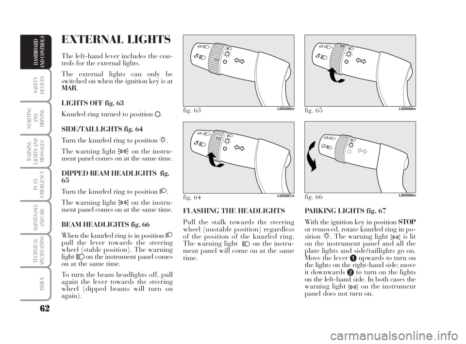
PARKING LIGHTS fig. 67
With the ignition key in position STOP
or removed, rotate knurled ring in po-
sition
6. The warning light 3is lit
on the instrument panel and all the
plate lights and side/taillights go on.
Move the lever
aupwards to turn on
the lights on the right-hand side; move
it downwards
bto turn on the lights
on the left-hand side. In both cases the
warning light
3on the instrument
panel does not turn on. FLASHING THE HEADLIGHTS
Pull the stalk towards the steering
wheel (unstable position) regardless
of the position of the knurled ring.
The warning light
1on the instru-
ment panel will come on at the same
time.
fig. 63L0D0066m
fig. 66L0D0069m
fig. 65L0D0068m
fig. 64L0D0067m
EXTERNAL LIGHTS
The left-hand lever includes the con-
trols for the external lights.
The external lights can only be
switched on when the ignition key is at
MAR.
LIGHTS OFF fig. 63
Knurled ring turned to position
å.
SIDE/TAILLIGHTS fig. 64
Turn the knurled ring to position
6.
The warning light
3on the instru-
ment panel comes on at the same time.
DIPPED BEAM HEADLIGHTS fig.
65
Turn the knurled ring to position
2.
The warning light
3on the instru-
ment panel comes on at the same time.
BEAM HEADLIGHTS fig. 66
When the knurled ring is in position
2pull the lever towards the steering
wheel (stable position). The warning
light
1on the instrument panel comes
on at the same time.
To turn the beam headlights off, pull
again the lever towards the steering
wheel (dipped beams will turn on
again).
038-094 MUSA 1ed GB 11-07-2008 14:10 Pagina 62
Page 64 of 218
63
SAFETY
DEVICES
STARTING
AND
DRIVING
WARNING
LIGHTS AND
MESSAGES
IN AN
EMERGENCY
MAINTENANCE
AND CARE
TECHNICALSPECIFICATIONS
INDEX
DASHBOARD
AND CONTROLS
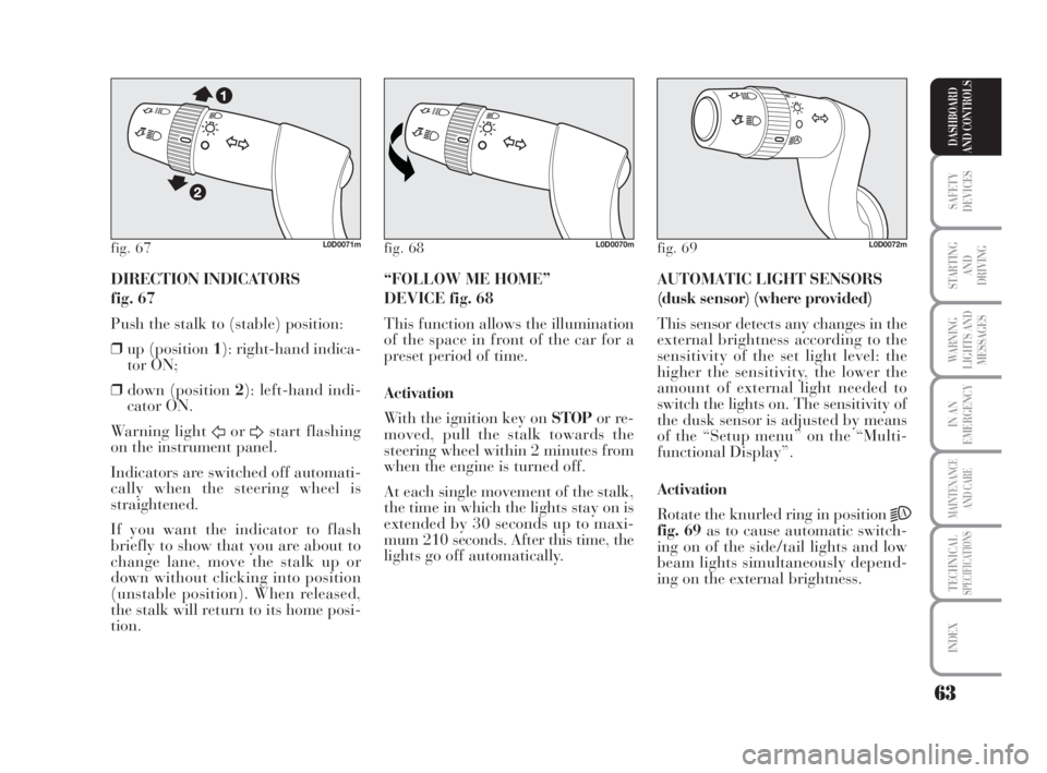
DIRECTION INDICATORS
fig. 67
Push the stalk to (stable) position:
❒up (position 1): right-hand indica-
tor ON;
❒down (position 2): left-hand indi-
cator ON.
Warning light
ForDstart flashing
on the instrument panel.
Indicators are switched off automati-
cally when the steering wheel is
straightened.
If you want the indicator to flash
briefly to show that you are about to
change lane, move the stalk up or
down without clicking into position
(unstable position). When released,
the stalk will return to its home posi-
tion.AUTOMATIC LIGHT SENSORS
(dusk sensor) (where provided)
This sensor detects any changes in the
external brightness according to the
sensitivity of the set light level: the
higher the sensitivity, the lower the
amount of external light needed to
switch the lights on. The sensitivity of
the dusk sensor is adjusted by means
of the “Setup menu” on the “Multi-
functional Display”.
Activation
Rotate the knurled ring in position
2A
fig. 69as to cause automatic switch-
ing on of the side/tail lights and low
beam lights simultaneously depend-
ing on the external brightness. “FOLLOW ME HOME”
DEVICE fig. 68
This function allows the illumination
of the space in front of the car for a
preset period of time.
Activation
With the ignition key on STOPor re-
moved, pull the stalk towards the
steering wheel within 2 minutes from
when the engine is turned off.
At each single movement of the stalk,
the time in which the lights stay on is
extended by 30 seconds up to maxi-
mum 210 seconds. After this time, the
lights go off automatically.
fig. 67L0D0071mfig. 68L0D0070mfig. 69L0D0072m
038-094 MUSA 1ed GB 11-07-2008 14:10 Pagina 63
Page 68 of 218
67
SAFETY
DEVICES
STARTING
AND
DRIVING
WARNING
LIGHTS AND
MESSAGES
IN AN
EMERGENCY
MAINTENANCE
AND CARE
TECHNICALSPECIFICATIONS
INDEX
DASHBOARD
AND CONTROLS
CRUISE CONTROL
(constant speed
regulator)
(where provided)
It is a device able to support the dri-
ver, with electronic control, which al-
lows driving at speed over 30 km/h
on long and straight dry roads (e.g.:
motorways), at a desired speed, with-
out pressing the accelerator pedal.
Therefore it is not suggested to use
this device on extra-urban roads with
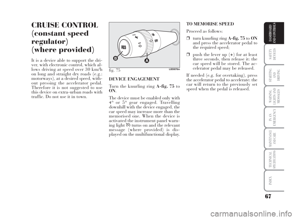
traffic. Do not use it in town.TO MEMORISE SPEED
Proceed as follows:
❒turn knurling ring A-fig. 75toON
and press the accelerator pedal to
the required speed;
❒push the lever up (+) for at least
three seconds, then release it: the
car speed will be stored. The ac-
celerator pedal may be released.
If needed (e.g. for overtaking), press
the accelerator pedal to accelerate: the
car will return to the previously set
speed when the pedal is released. DEVICE ENGAGEMENT
Turn the knurling ring A-fig. 75to
ON.
The device must be enabled only with
4
thor 5thgear engaged. Travelling
downhill with the device engaged, the
car speed may increase more than the
memorised one. When the device is
activated the instrument panel warn-
ing light Üturns on and the relevant
message (where provided) is dis-
played on the multifunctional display.
fig. 75L0D0076m
038-094 MUSA 1ed GB 11-07-2008 14:10 Pagina 67
Page 73 of 218
72
SAFETY
DEVICES
STARTING
AND
DRIVING
WARNING
LIGHTS AND
MESSAGES
IN AN
EMERGENCY
MAINTENANCE
AND CARE
TECHNICALSPECIFICATIONS
INDEX
DASHBOARD
AND CONTROLS
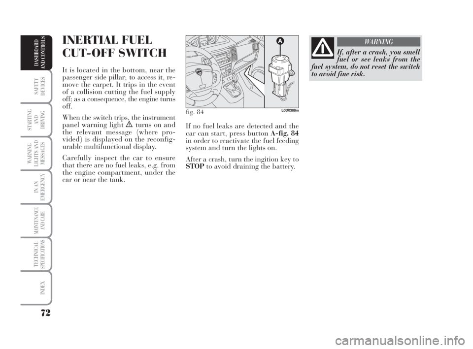
INERTIAL FUEL
CUT-OFF SWITCH
It is located in the bottom, near the
passenger side pillar; to access it, re-
move the carpet. It trips in the event
of a collision cutting the fuel supply
off; as a consequence, the engine turns
off.
When the switch trips, the instrument
panel warning light
èturns on and
the relevant message (where pro-
vided) is displayed on the reconfig-
urable multifunctional display.
Carefully inspect the car to ensure
that there are no fuel leaks, e.g. from
the engine compartment, under the
car or near the tank.
If, after a crash, you smell
fuel or see leaks from the
fuel system, do not reset the switch
to avoid fine risk.
WARNING
fig. 84L0D0388m
If no fuel leaks are detected and the
car can start, press button A-fig. 84
in order to reactivate the fuel feeding
system and turn the lights on.
After a crash, turn the ingition key to
STOPto avoid draining the battery.
038-094 MUSA 1ed GB 11-07-2008 14:10 Pagina 72
Page 81 of 218
80
SAFETY
DEVICES
STARTING
AND
DRIVING
WARNING
LIGHTS AND
MESSAGES
IN AN
EMERGENCY
MAINTENANCE
AND CARE
TECHNICALSPECIFICATIONS
INDEX
DASHBOARD
AND CONTROLS
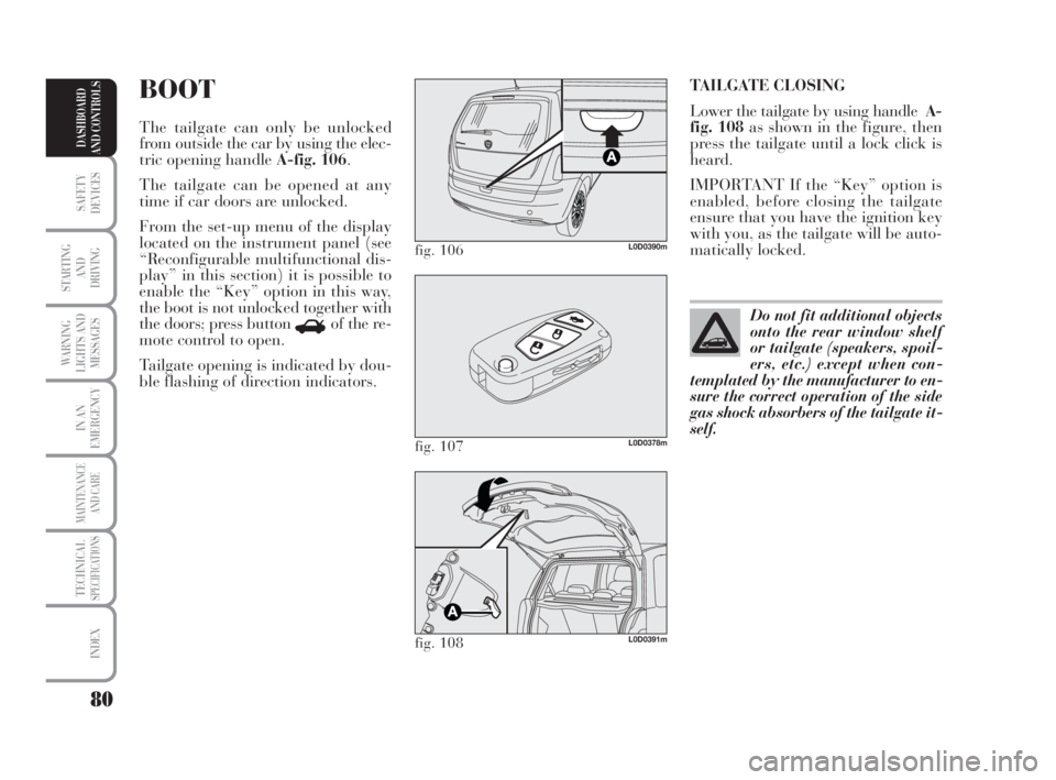
TAILGATE CLOSING
Lower the tailgate by using handleA-
fig. 108as shown in the figure, then
press the tailgate until a lock click is
heard.
IMPORTANT If the “Key” option is
enabled, before closing the tailgate
ensure that you have the ignition key
with you, as the tailgate will be auto-
matically locked.BOOT
The tailgate can only be unlocked
from outside the car by using the elec-
tric opening handle A-fig. 106.
The tailgate can be opened at any
time if car doors are unlocked.
From the set-up menu of the display
located on the instrument panel (see
“Reconfigurable multifunctional dis-
play” in this section) it is possible to
enable the “Key” option in this way,
the boot is not unlocked together with
the doors; press button
Rof the re-
mote control to open.
Tailgate opening is indicated by dou-
ble flashing of direction indicators.
fig. 106L0D0390m
fig. 107L0D0378m
fig. 108L0D0391m
Do not fit additional objects
onto the rear window shelf
or tailgate (speakers, spoil-
ers, etc.) except when con-
templated by the manufacturer to en-
sure the correct operation of the side
gas shock absorbers of the tailgate it-
self.
038-094 MUSA 1ed GB 11-07-2008 14:10 Pagina 80
Page 86 of 218
85
SAFETY
DEVICES
STARTING
AND
DRIVING
WARNING
LIGHTS AND
MESSAGES
IN AN
EMERGENCY
MAINTENANCE
AND CARE
TECHNICALSPECIFICATIONS
INDEX
DASHBOARD
AND CONTROLS
ABS SYSTEM
The car is fitted with an ABS braking
system, which prevents the wheels
from locking when braking, makes
the most of road grip and gives the
best control when emergency braking
under difficult road conditions.
The system is completed by EBD
(Electronic Braking Force Distribu-
tion), which distributes the braking
action between front and rear wheels.
IMPORTANT To achieve maximum
efficiency of the braking system, a
running in period of about 500 km is
required: during this time, avoid sud-
den, repeated and prolonged braking.SYSTEM INTERVENTION
Intervention of the ABS is detected by
a slight pulsing of the brake pedal ac-
companied by noise: such an event in-
dicates that you need to adjust your
speed to the type of road on which
you are travelling.
When the ABS intervenes it means
that you are approaching the grip
limit between tyres and road: slow
down to exploit all the available grip.
FAILURE INDICATIONS
ABS failure
It is indicated by the turning on of
warning light >on the instrument
panel together with the message
(where provided) shown on the re-
configurable multifunctional display
(see section “Warning lights and mes-
sages”).
In the case, the braking system will
work as normal without the extra po-
tentials offered by the ABS system.
Drive carefully to the nearest Lancia
Dealership to have the system
checked.When the ABS intervenes it
means that you are ap-
proaching the grip limit between
tyres and road: it is necessary to
slow down to adjust the speed ac-
cording to available grip.
WARNING
The ABS exploits the tyre
road grip to the full, but it
cannot improve it; you should there-
fore exercise great caution when dri-
ving on slippery surfaces without
taking unnecessary risks.
WARNING
038-094 MUSA 1ed GB 11-07-2008 14:10 Pagina 85