Cut Lancia Musa 2009 Owner handbook (in English)
[x] Cancel search | Manufacturer: LANCIA, Model Year: 2009, Model line: Musa, Model: Lancia Musa 2009Pages: 218, PDF Size: 3.7 MB
Page 8 of 218
7
SAFETY
DEVICES
STARTING
AND
DRIVING
WARNING
LIGHTS AND
MESSAGES
IN AN
EMERGENCY
MAINTENANCE
AND CARE
TECHNICALSPECIFICATIONS
INDEX
DASHBOARD
AND CONTROLSDASHBOARD ........................................................ 8
INSTRUMENT PANEL.......................................... 10
SYMBOLS ............................................................. 11
THE LANCIA CODE SYSTEM .............................. 11
THE KEY AND DOOR LOCKING KIT ................. 13
IGNITION DEVICE .............................................. 20
INSTRUMENTS ................................................... 21
MULTIFUNCTIONAL DISPLAY
(on two-line modal panel) ...................................... 22
MULTIFUNCTIONAL DISPLAY
(on three-line modal panel).................................... 25
ADJUSTING THE SEATS ..................................... 38
HEAD RESTRAINTS ............................................ 44
ADJUSTING THE STEERING WHEEL ............... 45
REARVIEW MIRRORS .......................................... 46
HEATING/CLIMATE CONTROL SYSTEM .......... 47
MANUAL CLIMATE CONTROL SYSTEM ........... 48
AUTOMATIC CLIMATE CONTROL
SYSTEM (TWO-ZONE) ....................................... 52
EXTERNAL LIGHTS ........................................... 62
WINDOW WASHING ............................................ 64
CRUISE CONTROL ............................................. 67CEILING LIGHTS ................................................. 69
LIGHT CONTROL BUTTONS .............................. 71
FUEL CUT-OFF INERTIAL SWITCH ................... 72
INTERNAL EQUIPMENT .................................... 73
SMOKERS KIT ...................................................... 75
SUN VISORS ......................................................... 76
SUNROOF ............................................................ 76
POWER WINDOWS ............................................. 78
BOOT .................................................................... 80
BONNET ............................................................... 82
ROOF BARS .......................................................... 83
HEADLIGHTS ...................................................... 84
ABS SYSTEM ....................................................... 85
EOBD SYSTEM .................................................... 86
SOUND SYSTEM .................................................. 87
ACCESSORIES PURCHASED BY THE OWNER .. 88
“DUALDRIVE” ELECTRIC POWER
STEERING SYSTEM ............................................ 89
PARKING SENSORS ............................................ 90
REFUELLING ...................................................... 92
ENVIRONMENTAL PROTECTION ..................... 94
DASHBOARD AND CONTROLS
007-037 MUSA 1ed GB 10-07-2008 9:36 Pagina 7
Page 15 of 218
14
SAFETY
DEVICES
STARTING
AND
DRIVING
WARNING
LIGHTS AND
MESSAGES
IN AN
EMERGENCY
MAINTENANCE
AND CARE
TECHNICALSPECIFICATIONS
INDEX
DASHBOARD
AND CONTROLS
IMPORTANT The remote control fre-
quency may be disturbed by radio
transmissions outside the car (e.g. cel-
lular phones, radio amateurs, etc.). If
this is the case, the remote control
may operate incorrectly.
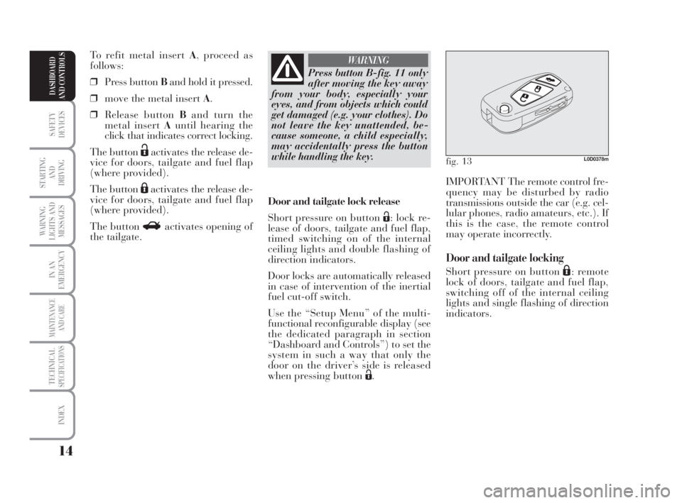
Door and tailgate locking
Short pressure on button Á: remote
lock of doors, tailgate and fuel flap,
switching off of the internal ceiling
lights and single flashing of direction
indicators. Door and tailgate lock release
Short pressure on button Ë: lock re-
lease of doors, tailgate and fuel flap,
timed switching on of the internal
ceiling lights and double flashing of
direction indicators.
Door locks are automatically released
in case of intervention of the inertial
fuel cut-off switch.
Use the “Setup Menu” of the multi-
functional reconfigurable display (see
the dedicated paragraph in section
“Dashboard and Controls”) to set the
system in such a way that only the
door on the driver’s side is released
when pressing button Ë. To refit metal insert A, proceed as
follows:
❒Press button Band hold it pressed.
❒move the metal insert A.
❒Release button Band turn the
metal insert Auntil hearing the
click that indicates correct locking.
The button
Ëactivates the release de-
vice for doors, tailgate and fuel flap
(where provided).
The button
Áactivates the release de-
vice for doors, tailgate and fuel flap
(where provided).
The button Ractivates opening of
the tailgate.
Press button B-fig. 11 only
after moving the key away
from your body, especially your
eyes, and from objects which could
get damaged (e.g. your clothes). Do
not leave the key unattended, be-
cause someone, a child especially,
may accidentally press the button
while handling the key.
WARNING
fig. 13L0D0378m
007-037 MUSA 1ed GB 10-07-2008 9:36 Pagina 14
Page 25 of 218
24
SAFETY
DEVICES
STARTING
AND
DRIVING
WARNING
LIGHTS AND
MESSAGES
IN AN
EMERGENCY
MAINTENANCE
AND CARE
TECHNICALSPECIFICATIONS
INDEX
DASHBOARD
AND CONTROLS
Setting the unit
To set the required unit (kilometres or
miles) proceed as follows:
❒press the button MODEseveral
times until the text “Unit” ap-
pears;
❒press the button +or–to change
the unit;
❒press the button MODEand hold
it pressed for over 2 seconds to
confirm the unit setting.
V iewing of the
fuel cut-off inertial switch
tripping
The screen automatically appears
whenever the fuel cut-off inertial
switch trips after a significant colli-
sion.
This switch stops fuel supply.
See the information provided in the
dedicated chapter “Fuel cut-off iner-
tial switch”. Set this function as follows:
❒press the button MODEseveral
times until the text “SPEED” ap-
pears;
❒press the button +to increase the
speed value (max. limit being 250
Km/h);
❒press the button –to reduce the
speed value (min. limit being 30
Km/h below which the system
goes back to “OFF” mode);
❒press the button MODEand hold
it pressed for over 2 seconds to
confirm the speed setting.
If, after the message
“FPSon” appears, you
smell fuel or see leaks from the fuel
supply system, do not reset the
switch to avoid the risk of starting a
fire.
WARNING
007-037 MUSA 1ed GB 10-07-2008 9:36 Pagina 24
Page 58 of 218
57
SAFETY
DEVICES
STARTING
AND
DRIVING
WARNING
LIGHTS AND
MESSAGES
IN AN
EMERGENCY
MAINTENANCE
AND CARE
TECHNICALSPECIFICATIONS
INDEX
DASHBOARD
AND CONTROLS
The distribution mode set is indicated
by the LEDs that light up on the se-
lected buttons.
In combined function mode the rele-
vant function is enabled simultane-
ously with those already set by press-
ing the corresponding button. If a
button is pressed for a function that
is active, the operation is cancelled
and the corresponding LED goes off.
To restore automatic air distribution
control after a manual selection, press
buttonAUTO.
When the driver selects air distribu-
tion to the windscreen, the air distri-
bution on the passenger’s side too is
aligned to the windscreen. The pas-
senger can select a different distribu-
tion mode by pressing the corre-
sponding buttons.Buttons
AUTO H-N
(automatic
operation)
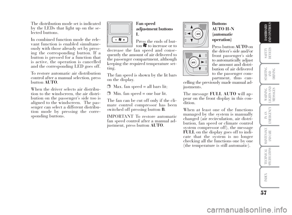
Press button AUTOon
the driver’s side and/or
front passenger’s side
to automatically adjust
the amount and distri-
bution of air delivered
to the passenger com-
partment, thus can-
celling the previously made manual ad-
justments.
The message FULL AUTOwill ap-
pear on the front display in this con-
dition.
When at least one of the functions
managed by the system is manually
changed (air recirculation, air distri-
bution, fan speed or climate control
system compressor off), the message
FULLon the display goes off to indi-
cate that the system is no longer
checking all the functions one by one
(the temperature is still automatic). Fan speed
adjustment buttons
L
Press the ends of but-
ton
pto increase or to
decrease the fan speed and conse-
quently the amount of air delivered to
the passenger compartment, although
keeping the required temperature set-
ting.
The fan speed is shown by the lit bars
on the display.
❒Max. fan speed = all bars lit;
❒Min. fan speed = one bar lit.
The fan can be cut off only if the cli-
mate control compressor has been
switched off pressing button B.
IMPORTANT To restore automatic
fan speed control after a manual ad-
justment, press button AUTO.
038-094 MUSA 1ed GB 11-07-2008 14:10 Pagina 57
Page 73 of 218
72
SAFETY
DEVICES
STARTING
AND
DRIVING
WARNING
LIGHTS AND
MESSAGES
IN AN
EMERGENCY
MAINTENANCE
AND CARE
TECHNICALSPECIFICATIONS
INDEX
DASHBOARD
AND CONTROLS
INERTIAL FUEL
CUT-OFF SWITCH
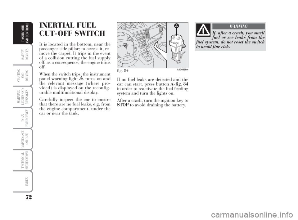
It is located in the bottom, near the
passenger side pillar; to access it, re-
move the carpet. It trips in the event
of a collision cutting the fuel supply
off; as a consequence, the engine turns
off.
When the switch trips, the instrument
panel warning light
èturns on and
the relevant message (where pro-
vided) is displayed on the reconfig-
urable multifunctional display.
Carefully inspect the car to ensure
that there are no fuel leaks, e.g. from
the engine compartment, under the
car or near the tank.
If, after a crash, you smell
fuel or see leaks from the
fuel system, do not reset the switch
to avoid fine risk.
WARNING
fig. 84L0D0388m
If no fuel leaks are detected and the
car can start, press button A-fig. 84
in order to reactivate the fuel feeding
system and turn the lights on.
After a crash, turn the ingition key to
STOPto avoid draining the battery.
038-094 MUSA 1ed GB 11-07-2008 14:10 Pagina 72
Page 77 of 218
SUN VISORS
These are arranged at the sides of the
internal rearview mirror. They may be
oriented frontally and to the side.
On certain versions, a courtesy mirror
can be applied to the back of the sun
visor.
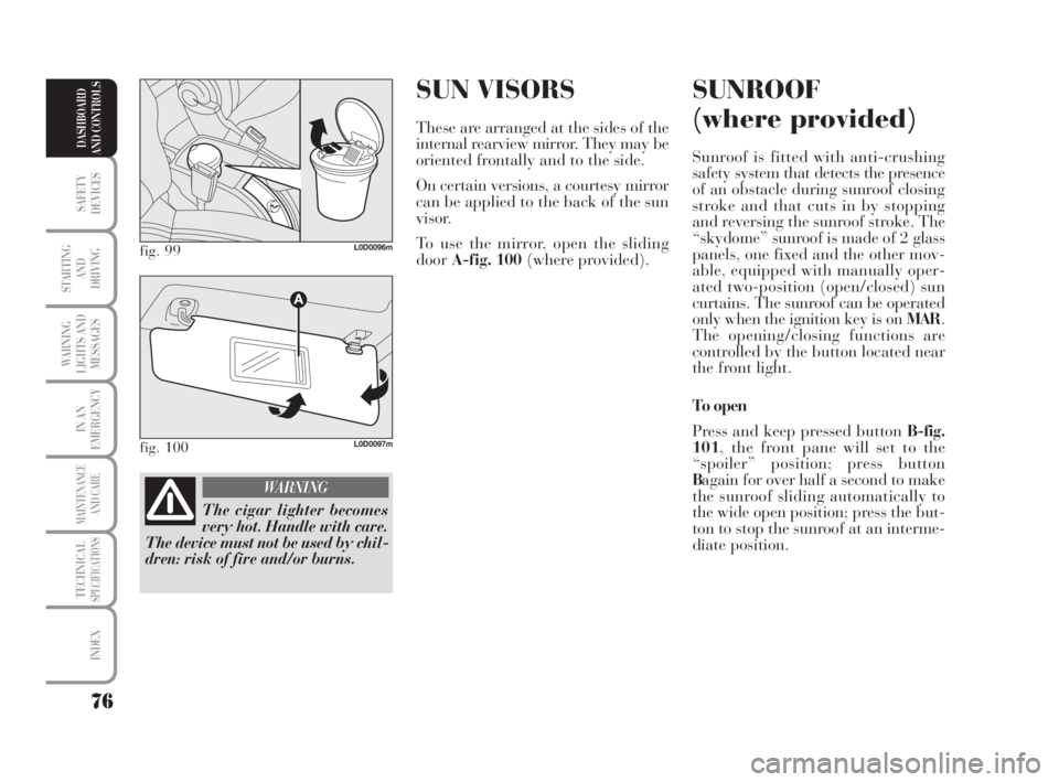
To use the mirror, open the sliding
doorA-fig. 100(where provided).
SUNROOF
(where provided)
Sunroof is fitted with anti-crushing
safety system that detects the presence
of an obstacle during sunroof closing
stroke and that cuts in by stopping
and reversing the sunroof stroke. The
“skydome” sunroof is made of 2 glass
panels, one fixed and the other mov-
able, equipped with manually oper-
ated two-position (open/closed) sun
curtains. The sunroof can be operated
only when the ignition key is on MAR.
The opening/closing functions are
controlled by the button located near
the front light.
To open
Press and keep pressed button B-fig.
101, the front pane will set to the
“spoiler” position; press button
Bagain for over half a second to make
the sunroof sliding automatically to
the wide open position; press the but-
ton to stop the sunroof at an interme-
diate position.
76
SAFETY
DEVICES
STARTING
AND
DRIVING
WARNING
LIGHTS AND
MESSAGES
IN AN
EMERGENCY
MAINTENANCE
AND CARE
TECHNICALSPECIFICATIONS
INDEX
DASHBOARD
AND CONTROLS
fig. 99L0D0096m
fig. 100L0D0097m
The cigar lighter becomes
very hot. Handle with care.
The device must not be used by chil-
dren: risk of fire and/or burns.
WARNING
038-094 MUSA 1ed GB 11-07-2008 14:10 Pagina 76
Page 102 of 218
101
STARTING
AND
DRIVING
WARNING
LIGHTS AND
MESSAGES
IN AN
EMERGENCY
MAINTENANCE
AND CARE
TECHNICALSPECIFICATIONS
INDEX
DASHBOARD
AND CONTROLS
SAFETY
DEVICES
HOW TO KEEP SAFETY
BELTS ALWAYS EFFICIENT
❒Always use the seat belts with the
tap taut and never twisted; make
sure that it is free to run without
impediments.
❒Replace the belt after a serious ac-
cident even if it does not appear
damaged. Always replace the belt
if the pretensioners were deployed.
❒To clean the belt, wash by hand
with water and mild soap, rinse
and leave to dry in the shade. Do
not use strong detergents, bleach,
paints or any other chemical sub-
stance which could damage the
belt fibres.
❒Keep the reels dry: correct opera-
tion is ensured only if there are no
water infiltrations in the reels.
❒Replace the seat belt when show-
ing significant signs of wear or
cuts.CARRYING
CHILDREN
SAFELY
For optimal protection in the event of
a crash, all passengers must be seated
and wear adequate restraint systems.
This is even more important for chil-
dren.
This is a compulsory requirement in
all EC member countries according to
EC Directive 2003/20/EC.
A child’s head is larger and heavier in
proportion to his/her body and the
child’s muscular and bone structures
are not fully developed. For this rea-
son, they require restraint systems
which are different from those used
by adults to protect them in the event
of an accident.
If the belt has been sub-
jected to a heavy stress, for
example after an accident, it should
be changed completely together with
the anchors, anchor fastening screws
and the pretensioner. In fact, even if
the belt has no visible defects, it
could have lost its resilience.
WARNING
Each seat belt must be
worn by one person only.
Do not carry children on your lap
with one seat belt protecting both.
In general, do not place any objects
between the passenger and the belt.
WARNING
095-112 MUSA 1ed GB 10-07-2008 9:37 Pagina 101
Page 133 of 218
132
IN AN
EMERGENCY
MAINTENANCE
AND CARE
TECHNICALSPECIFICATIONS
INDEX
DASHBOARD
AND CONTROLS
SAFETY
DEVICES
STARTING
AND
DRIVING
WARNING
LIGHTS AND
MESSAGES
GENERAL FAILURE
INDICATION
(amber)
The warning light turns on in
the following circumstances.
Externallight failure
The warning light comes on (on some
versions only) when a failure is de-
tected in one of the following lights:
– tail lights
– stop lights (excluding 3
rdstop)
– rear fog lights
– direction indicators
– plate lights.
The fault identified in the lights above
may be due to: one or more burnt
lamps, a blown protection fuse or in-
terruption of the electrical connection.
The display will show the dedicated
message.
è
Fresh air filter clogged
(where provided)
The warning light turns on when the
particulate filter is clogged and the
driving conditions do not enable au-
tomatic activation of the regeneration
procedure.
To allow the regeneration procedure,
keep the car running until the warn-
ing light turns off.
The display will show the dedicated
message.
Engine oil pressure sensor failure
The warning light turns on when a
failure is detected in the engine oil
pressure sensor. Go to a Lancia Deal-
ership as soon as possible.Twilight/rain sensor failure
The warning light turns on when a
failure is detected in the twilight/rain
sensors. Go to a Lancia Dealership as
soon as possible.
The display will show the dedicated
message.
Fuel cut-off switch tripped
The warning light comes on when the
fuel cut-off switch trips.
The display will show the dedicated
message.
Speed limit exceeded
The display shows the dedicated mes-
sage when the car exceeds the set
speed limit (see “Multifunction Dis-
play” in section “Dashboard and con-
trols”).
125-134 MUSA 1ed GB 10-07-2008 9:38 Pagina 132
Page 140 of 218
139
WARNING
LIGHTS AND
MESSAGES
MAINTENANCE
AND CARE
TECHNICALSPECIFICATIONS
INDEX
DASHBOARD
AND CONTROLS
SAFETY
DEVICES
STARTING
AND
DRIVING
IN AN
EMERGENCY
fig. 3L0D0361m
fig. 4L0D0362m
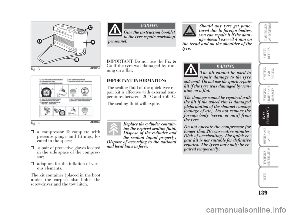
❒a compressor Dcomplete with
pressure gauge and fittings, lo-
cated in the space;
❒a pair of protective gloves located
in the side space of the compres-
sor;
❒adaptors for the inflation of vari-
ous elements.
The kit container (placed in the boot
under the carpet) also holds the
screwdriver and the tow hitch.
Give the instruction booklet
to the tyre repair workshop
personnel.
WARNING
IMPORTANT Do not use the Fix &
Go if the tyre was damaged by run-
ning on a flat.
IMPORTANT INFORMATION:
The sealing fluid of the quick tyre re-
pair kit is effective with external tem-
peratures between –20 °C and +50 °C.
The sealing fluid will expire.
The kit cannot be used to
repair damage to the tyre
sidewall. Do not use the quick repair
kit if the tyre was damaged by run-
ning on a flat.
The damage cannot be repaired with
the kit if the wheel rim is damaged
(deformation of the channel causing
leakage of air). Do not remove the
foreign body (screw or nail) from
the tyre.
Do not operate the compressor for
longer than 20 consecutive minutes.
Risk of overheating. The quick re-
pair kit is not suitable for definitive
repairs. The tyres may only be re-
paired temporarily.
WARNING
Should any tyre get punc-
tured due to foreign bodies,
you can repair it if the dam-
age doesn’t exceed 4 mm on
the tread and on the shoulder of the
tyre.
Replace the cylinder contain-
ing the expired sealing fluid.
Dispose of the cylinder and
the sealant liquid properly.
Dispose of according to the national
and local laws in force.
135-164 MUSA 1ed GB 10-07-2008 9:38 Pagina 139
Page 157 of 218

156
WARNING
LIGHTS AND
MESSAGES
MAINTENANCE
AND CARE
TECHNICALSPECIFICATIONS
INDEX
DASHBOARD
AND CONTROLS
SAFETY
DEVICES
STARTING
AND
DRIVING
IN AN
EMERGENCY
BOOT LIGHT fig. 34
To change the bulb, proceed as fol-
lows:
❒open the tailgate;
❒remove the light Alevering in the
point shown by the arrow.
❒open the protection Band replace
the snap-fitted bulb;
❒re-close the protective cover Bon
the lens;
❒refit the light Ainserting it in its
correct position firstly on one end
and then on the other until it
clicks into place.
fig. 34L0D0197m
IF A FUSE BLOWS
GENERALITIES fig. 35
The fuse is a protective device for the
electric system: it comes into action
(i.e. it cuts off) mainly due to a fault
or improper action on the system.
Check the efficiency of the corre-
sponding fuse when a device does not
work: the conducting element Amust
not be interrupted. If it is, replace the
blown fuse with another with the
same amperage (same colour).
B: intact fuse.
C: fuse with damaged filament.
To replace a fuse use the pliers Dat-
tached to the fuse box on the instru-
ment dashboard.
fig. 35L0D0198m
If the fuse should fail again,
contact a Lancia Dealer-
ship.
WARNING
Never change a fuse with an-
other with a higher amp rat-
ing; DANGER OF FIRE.
If a general fuse (MEGA-
FUSE,MIDI-FUSE, MAXI-
FUSE) cuts in, contact a Lancia Deal-
ership.
WARNING
Before changing a fuse,
check that the ignition key
has been removed and that all the
other electric devices have been
turned off/disabled.
WARNING
135-164 MUSA 1ed GB 10-07-2008 9:38 Pagina 156