fuel pump Lancia Musa 2009 Owner handbook (in English)
[x] Cancel search | Manufacturer: LANCIA, Model Year: 2009, Model line: Musa, Model: Lancia Musa 2009Pages: 218, PDF Size: 3.7 MB
Page 93 of 218

92
SAFETY
DEVICES
STARTING
AND
DRIVING
WARNING
LIGHTS AND
MESSAGES
IN AN
EMERGENCY
MAINTENANCE
AND CARE
TECHNICALSPECIFICATIONS
INDEX
DASHBOARD
AND CONTROLS
CAR REFUELLING
PETROL ENGINES
Use only unleaded petrol.
To avoid mistakes, the diameter of the
fuel filler is too small to introduce the
beak of a leaded petrol pump. The
petrol octane rating (RON) must not
be lower than 95.
IMPORTANT An inefficient catalyst
leads to harmful exhaust emissions,
thus contributing to air pollution.
IMPORTANT Never use leaded petrol,
even in small amounts or in an emer-
gency, as this would damage the cat-
alyst beyond repair.MULTIJET ENGINES
Operation at low temperatures
If the outside temperature is very low,
the diesel thickens due to the forma-
tion of paraffin clots with consequent
anomalous operation of the fuel sup-
ply system.
In order to avoid these problems, dif-
ferent types of diesel are distributed
according to the season: summer type,
winter type and arctic type (cold,
mountain areas). If refuelling with
diesel fuel whose features are not suit-
able to the temperature of use, it is
advisable to mix TUTELA DIESEL
ART additive in the proportions
shown on the container with the fuel.
Pour the additive into the tank before
the fuel.
When using or parking the car for a
long time in the mountains or cold ar-
eas, it is advisable to refuel using lo-
cally available fuel.
In this case, it is also advisable to keep
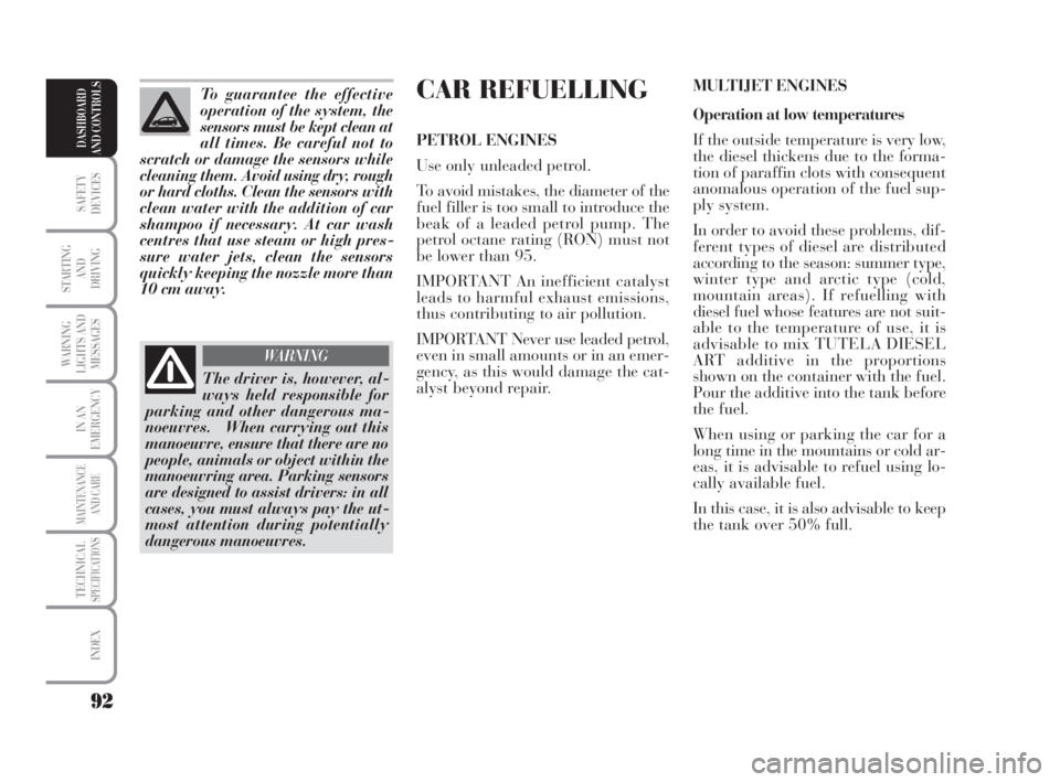
the tank over 50% full. To guarantee the effective
operation of the system, the
sensors must be kept clean at
all times. Be careful not to
scratch or damage the sensors while
cleaning them. Avoid using dry, rough
or hard cloths. Clean the sensors with
clean water with the addition of car
shampoo if necessary. At car wash
centres that use steam or high pres-
sure water jets, clean the sensors
quickly keeping the nozzle more than
10 cm away.
The driver is, however, al-
ways held responsible for
parking and other dangerous ma-
noeuvres. When carrying out this
manoeuvre, ensure that there are no
people, animals or object within the
manoeuvring area. Parking sensors
are designed to assist drivers: in all
cases, you must always pay the ut-
most attention during potentially
dangerous manoeuvres.
WARNING
038-094 MUSA 1ed GB 11-07-2008 14:11 Pagina 92
Page 94 of 218

93
SAFETY
DEVICES
STARTING
AND
DRIVING
WARNING
LIGHTS AND
MESSAGES
IN AN
EMERGENCY
MAINTENANCE
AND CARE
TECHNICALSPECIFICATIONS
INDEX
DASHBOARD
AND CONTROLS
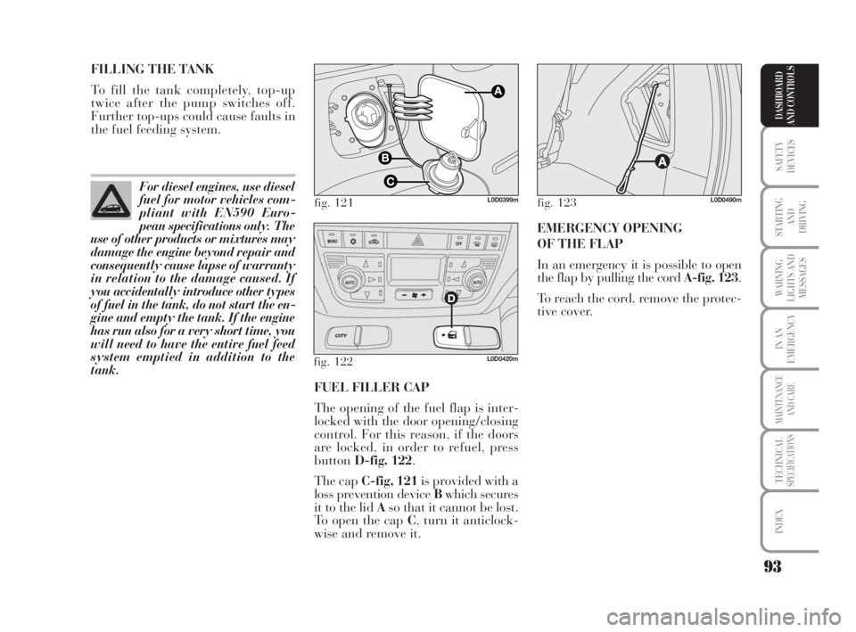
FUEL FILLER CAP
The opening of the fuel flap is inter-
locked with the door opening/closing
control. For this reason, if the doors
are locked, in order to refuel, press
buttonD-fig. 122.
The cap C-fig, 121is provided with a
loss prevention device Bwhich secures
it to the lid Aso that it cannot be lost.
To open the cap C, turn it anticlock-
wise and remove it. FILLING THE TANK
To fill the tank completely, top-up
twice after the pump switches off.
Further top-ups could cause faults in
the fuel feeding system.
For diesel engines, use diesel
fuel for motor vehicles com-
pliant with EN590 Euro-
pean specifications only. The
use of other products or mixtures may
damage the engine beyond repair and
consequently cause lapse of warranty
in relation to the damage caused. If
you accidentally introduce other types
of fuel in the tank, do not start the en-
gine and empty the tank. If the engine
has run also for a very short time, you
will need to have the entire fuel feed
system emptied in addition to the
tank.
fig. 121L0D0399m
fig. 122L0D0420m
EMERGENCY OPENING
OF THE FLAP
In an emergency it is possible to open
the flap by pulling the cord A-fig. 123.
To reach the cord, remove the protec-
tive cover.
fig. 123L0D0490m
038-094 MUSA 1ed GB 11-07-2008 14:11 Pagina 93
Page 161 of 218

160
WARNING
LIGHTS AND
MESSAGES
MAINTENANCE
AND CARE
TECHNICALSPECIFICATIONS
INDEX
DASHBOARD
AND CONTROLS
SAFETY
DEVICES
STARTING
AND
DRIVING
IN AN
EMERGENCY
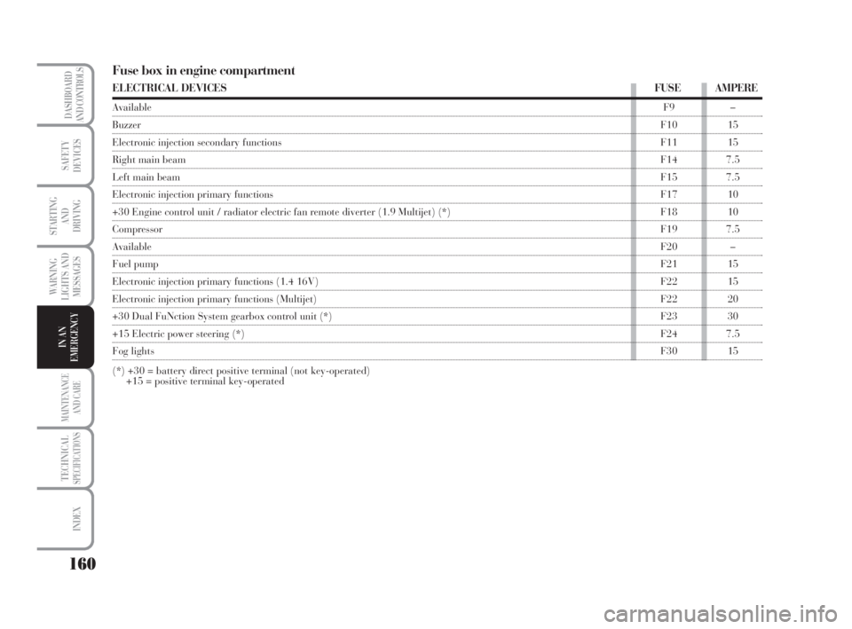
Fuse box in engine compartment
ELECTRICAL DEVICESFUSEAMPERE
AvailableF9 –
BuzzerF10 15
Electronic injection secondary functionsF11 15
Right main beam F14 7.5
Left main beam F15 7.5
Electronic injection primary functionsF17 10
+30 Engine control unit / radiator electric fan remote diverter (1.9 Multijet) (*) F18 10
CompressorF19 7.5
AvailableF20 –
Fuel pump F21 15
Electronic injection primary functions (1.4 16V)F22 15
Electronic injection primary functions (Multijet)F22 20
+30 Dual FuNction System gearbox control unit (*)F23 30
+15 Electric power steering (*)F24 7.5
Fog lightsF30 15
(*) +30 = battery direct positive terminal (not key-operated)
+15 = positive terminal key-operated
135-164 MUSA 1ed GB 10-07-2008 9:38 Pagina 160