start stop button Lancia Musa 2009 Owner handbook (in English)
[x] Cancel search | Manufacturer: LANCIA, Model Year: 2009, Model line: Musa, Model: Lancia Musa 2009Pages: 218, PDF Size: 3.7 MB
Page 25 of 218
24
SAFETY
DEVICES
STARTING
AND
DRIVING
WARNING
LIGHTS AND
MESSAGES
IN AN
EMERGENCY
MAINTENANCE
AND CARE
TECHNICALSPECIFICATIONS
INDEX
DASHBOARD
AND CONTROLS
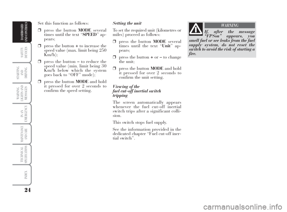
Setting the unit
To set the required unit (kilometres or
miles) proceed as follows:
❒press the button MODEseveral
times until the text “Unit” ap-
pears;
❒press the button +or–to change
the unit;
❒press the button MODEand hold
it pressed for over 2 seconds to
confirm the unit setting.
V iewing of the
fuel cut-off inertial switch
tripping
The screen automatically appears
whenever the fuel cut-off inertial
switch trips after a significant colli-
sion.
This switch stops fuel supply.
See the information provided in the
dedicated chapter “Fuel cut-off iner-
tial switch”. Set this function as follows:
❒press the button MODEseveral
times until the text “SPEED” ap-
pears;
❒press the button +to increase the
speed value (max. limit being 250
Km/h);
❒press the button –to reduce the
speed value (min. limit being 30
Km/h below which the system
goes back to “OFF” mode);
❒press the button MODEand hold
it pressed for over 2 seconds to
confirm the speed setting.
If, after the message
“FPSon” appears, you
smell fuel or see leaks from the fuel
supply system, do not reset the
switch to avoid the risk of starting a
fire.
WARNING
007-037 MUSA 1ed GB 10-07-2008 9:36 Pagina 24
Page 28 of 218
27
SAFETY
DEVICES
STARTING
AND
DRIVING
WARNING
LIGHTS AND
MESSAGES
IN AN
EMERGENCY
MAINTENANCE
AND CARE
TECHNICALSPECIFICATIONS
INDEX
DASHBOARD
AND CONTROLS
Day
YearMonth Example:
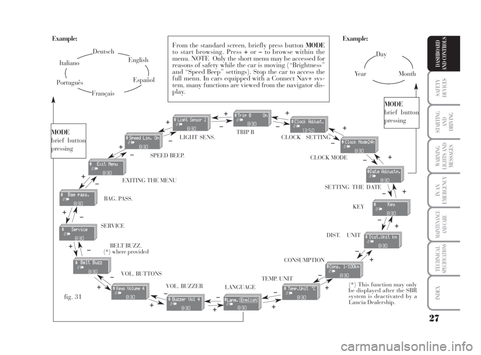
EXITING THE MENUSPEED BEEP.CLOCK SETTING
LIGHT SENS.TRIP B
CLOCK MODE
SETTING THE DATE
KEY
DIST. UNIT
VOL. BUTTONS
VOL. BUZZER SERVICE
LANGUAGETEMP. UNIT
Example:
– +
+– – –
+ +
–
–
+
+++
–––
+ +
–
MODE
brief button
pressing
From the standard screen, briefly press button MODE
to start browsing. Press +or–to browse within the
menu. NOTE Only the short menu may be accessed for
reasons of safety while the car is moving (“Brightness”
and “Speed Beep” settings). Stop the car to access the
full menu. In cars equipped with a Connect Nav+ sys-
tem, many functions are viewed from the navigator dis-
play.
–
+ +
–
MODE
brief button
pressing
Deutsch
English
Español
Italiano
Português
Français
(*) This function may only
be displayed after the SBR
system is deactivated by a
Lancia Dealership.
fig. 31
+
– +
–+
–
+
–
+
–
CONSUMPTION BAG. PASS.
BELT BUZZ.
(*) where provided
007-037 MUSA 1ed GB 10-07-2008 9:36 Pagina 27
Page 44 of 218
43
SAFETY
DEVICES
STARTING
AND
DRIVING
WARNING
LIGHTS AND
MESSAGES
IN AN
EMERGENCY
MAINTENANCE
AND CARE
TECHNICALSPECIFICATIONS
INDEX
DASHBOARD
AND CONTROLS
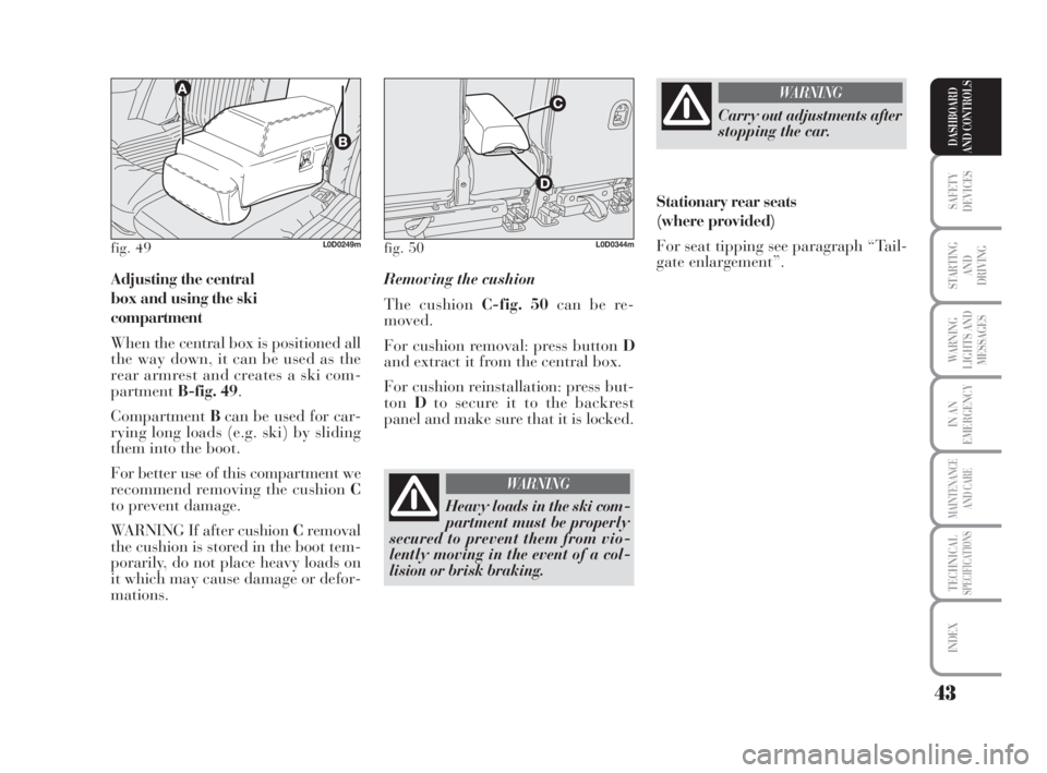
Adjusting the central
box and using the ski
compartment
When the central box is positioned all
the way down, it can be used as the
rear armrest and creates a ski com-
partmentB-fig. 49.
CompartmentBcan be used for car-
rying long loads (e.g. ski) by sliding
them into the boot.
For better use of this compartment we
recommend removing the cushion C
to prevent damage.
WARNING If after cushion Cremoval
the cushion is stored in the boot tem-
porarily, do not place heavy loads on
it which may cause damage or defor-
mations.Removing the cushion
The cushion C-fig. 50can be re-
moved.
For cushion removal: press button D
and extract it from the central box.
For cushion reinstallation: press but-
tonDto secure it to the backrest
panel and make sure that it is locked.
fig. 49L0D0249mfig. 50L0D0344m
Heavy loads in the ski com-
partment must be properly
secured to prevent them from vio-
lently moving in the event of a col-
lision or brisk braking.
WARNING
Carry out adjustments after
stopping the car.
WARNING
Stationary rear seats
(where provided)
For seat tipping see paragraph “Tail-
gate enlargement”.
038-094 MUSA 1ed GB 11-07-2008 14:10 Pagina 43
Page 51 of 218
50
SAFETY
DEVICES
STARTING
AND
DRIVING
WARNING
LIGHTS AND
MESSAGES
IN AN
EMERGENCY
MAINTENANCE
AND CARE
TECHNICALSPECIFICATIONS
INDEX
DASHBOARD
AND CONTROLS
Window demisting
In the event of considerable outside
moisture and/or rain and/or consid-
erable differences in temperature in-
side and outside the passenger com-
partment, perform the following pre-
ventive demisting procedure:
❒stop internal air recirculation by
placing knob F-fig. 61on
Ú;
❒position the rotating knurled ring
Bon the red section;
❒turn knob Aon 2;
❒position the rotating knurled ring
Eon
-with the option of shift-
ing to position ƒif the windows
do not get misted.
IMPORTANT The climate control sys-
tem is very useful to make window
demisting faster. To do this, proceed
as previously described and start the
system by pressing buttonD. FRONT WINDOW FAST
DEMISTING/DEFROSTING
(WINDSCREEN AND SIDE
WINDOWS)
Proceed as follows:
❒position the rotating knurled ring
Bon the red section;
❒turn knob Aon 4
-;
❒position the rotating knurled ring E
on
-;
❒stop internal air recirculation by
placing knob Fon
Ú.
After demisting/defrosting, operate
the controls to restore the required
comfort. FAST HEATING
Proceed as follows:
❒close all the vents on the dash-
board;
❒position the rotating knurled ring
B-fig. 61on the red section;
❒turn knob Aon 4
-;
❒position the rotating knurled ring
Eon
≈.
038-094 MUSA 1ed GB 11-07-2008 14:10 Pagina 50
Page 52 of 218
51
SAFETY
DEVICES
STARTING
AND
DRIVING
WARNING
LIGHTS AND
MESSAGES
IN AN
EMERGENCY
MAINTENANCE
AND CARE
TECHNICALSPECIFICATIONS
INDEX
DASHBOARD
AND CONTROLS
DEMISTING/DEFROSTING
OF REAR WINDOW DEMISTER
AND ELECTRICAL DOOR
MIRRORS (where provided)
Press button C-fig. 61to enable this
function. When the function is active,
a led on the button goes on.
This is a timed function, which is au-
tomatically disabled by the system af-
ter a preset time. Press button C
again to disable the function in ad-
vance.
IMPORTANT Do not affix decals on
the inside of the rear window over the
heating filaments to avoid damage
that might cause it to stop working
properly.Regulating cooling
Proceed as follows:
❒stop internal air recirculation by
placing knob F-fig. 61on
Ú;
❒turn the rotating knurled ring B
clockwise to increase the temper-
ature;
❒turn knob Aanticlockwise to re-
duce the fan speed.
SERVICING THE SYSTEM
Run the climate control system for at
least 10 minutes every month during
the winter. Have the system inspected
at a Lancia Dealership before the
summer. CLIMATE CONTROL
(cooling and de-humidification)
Proceed as follows:
❒position the rotating knurled ring
B-fig. 61on the blue section to se-
lect the required temperature;
❒turn knob Ato the required speed;
❒position the knurled ring Eon
«;
❒position the knob Fon
…;
❒press button D
√(the LED on the
button goes on).
038-094 MUSA 1ed GB 11-07-2008 14:10 Pagina 51
Page 61 of 218
60
SAFETY
DEVICES
STARTING
AND
DRIVING
WARNING
LIGHTS AND
MESSAGES
IN AN
EMERGENCY
MAINTENANCE
AND CARE
TECHNICALSPECIFICATIONS
INDEX
DASHBOARD
AND CONTROLS
IMPORTANT The fast window
demisting/defrosting function remains
engaged for approx. 3 minutes start-
ing from the time when the engine
coolant exceeds 50°C (petrol versions)
or 35°C (Multijet versions).
When this function is active, the LED
of the corresponding button switches
on and that of the rear window
demister. The text FULL AUTOgoes
off on the display.
You can only adjust the fan speed and
switch the rear window demister off
manually when this function is active.
To restore operating conditions before
this function is activated, press but-
tonF, the air recirculation button C,
the compressor button Bor button
AUTO NorH. Fast window
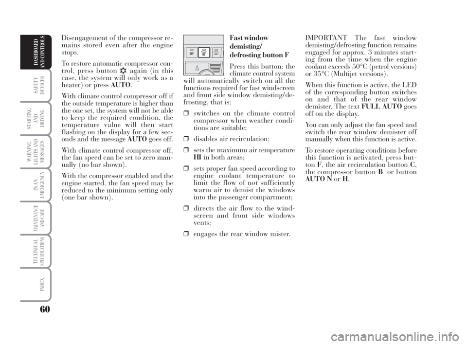
demisting/
defrosting button F
Press this button: the
climate control system
will automatically switch on all the
functions required for fast windscreen
and front side window demisting/de-
frosting, that is:
❒switches on the climate control
compressor when weather condi-
tions are suitable;
❒disables air recirculation;
❒sets the maximum air temperature
HIin both areas;
❒sets proper fan speed according to
engine coolant temperature to
limit the flow of not sufficiently
warm air to demist the windows
into the passenger compartment;
❒directs the air flow to the wind-
screen and front side windows
vents;
❒engages the rear window mister.Disengagement of the compressor re-
mains stored even after the engine
stops.
To restore automatic compressor con-
trol, press button
√again (in this
case, the system will only work as a
heater) or press AUTO.
With climate control compressor off if
the outside temperature is higher than
the one set, the system will not be able
to keep the required condition, the
temperature value will then start
flashing on the display for a few sec-
onds and the message AUTOgoes off.
With climate control compressor off,
the fan speed can be set to zero man-
ually (no bar shown).
With the compressor enabled and the
engine started, the fan speed may be
reduced to the minimum setting only
(one bar shown).
038-094 MUSA 1ed GB 11-07-2008 14:10 Pagina 60
Page 62 of 218
61
SAFETY
DEVICES
STARTING
AND
DRIVING
WARNING
LIGHTS AND
MESSAGES
IN AN
EMERGENCY
MAINTENANCE
AND CARE
TECHNICALSPECIFICATIONS
INDEX
DASHBOARD
AND CONTROLS
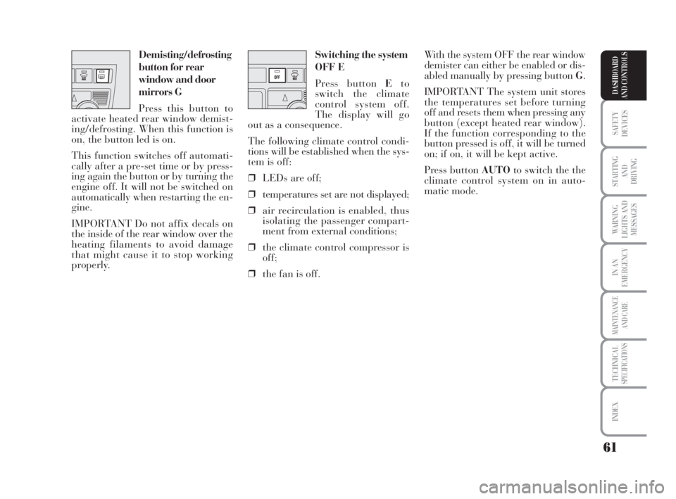
Switching the system
OFF E
Press button Eto
switch the climate
control system off.
The display will go
out as a consequence.
The following climate control condi-
tions will be established when the sys-
tem is off:
❒LEDs are off;
❒temperatures set are not displayed;
❒air recirculation is enabled, thus
isolating the passenger compart-
ment from external conditions;
❒the climate control compressor is
off;
❒the fan is off.With the system OFF the rear window
demister can either be enabled or dis-
abled manually by pressing button G.
IMPORTANT The system unit stores
the temperatures set before turning
off and resets them when pressing any
button (except heated rear window).
If the function corresponding to the
button pressed is off, it will be turned
on; if on, it will be kept active.
Press button AUTOto switch the the
climate control system on in auto-
matic mode. Demisting/defrosting
button for rear
window and door
mirrors G
Press this button to
activate heated rear window demist-
ing/defrosting. When this function is
on, the button led is on.
This function switches off automati-
cally after a pre-set time or by press-
ing again the button or by turning the
engine off. It will not be switched on
automatically when restarting the en-
gine.
IMPORTANT Do not affix decals on
the inside of the rear window over the
heating filaments to avoid damage
that might cause it to stop working
properly.
038-094 MUSA 1ed GB 11-07-2008 14:10 Pagina 61
Page 69 of 218
68
SAFETY
DEVICES
STARTING
AND
DRIVING
WARNING
LIGHTS AND
MESSAGES
IN AN
EMERGENCY
MAINTENANCE
AND CARE
TECHNICALSPECIFICATIONS
INDEX
DASHBOARD
AND CONTROLS
DEVICE DISENGAGEMENT
Turn the knurled ring A-fig. 75to
OFFor the ignition key to STOP. In
addition, the device is automatically
disengaged in one of the following
cases:
❒pressing the brake pedal. TO REDUCE MEMORISED SPEED
The stored speed can be increased in
two ways:
❒disengaging the device and then
memorising the new speed;
or
❒moving the stalk downwards (
–)
until reaching the new speed which
will be memorised automatically.
Each operation of the stalk will cor-
respond to a slight reduction in speed
(about 1 km/h), while keeping the
stalk downwards will correspond to a
continuous speed reduction. RESTORING STORED SPEED
If the device has been disengaged for
example pressing the brake or clutch
pedal, the memorised speed can be re-
set as follows:
❒accelerate gradually until reaching
a speed approaching the one
memorised;
❒engage the gear selected at the
time of speed memorising (4
thor
5thgear);
❒press the button RES B.
TO INCREASE THE MEMORISED
SPEED
The stored speed can be increased
in two ways:
❒pressing the accelerator and then
memorising the new speed
reached;
or
❒moving the stalk upwards (
+).
Each operation of the stalk will cor-
respond to a slight increase in speed
(about 1 km/h), while keeping the
stalk upwards will correspond to a
continuous speed increase.
While travelling with the
device engaged, do not set
the gearshift lever to neutral.
WARNING
In case of malfunctioning or
fault of the device, turn the
knurled ring to OFF and contact the
Lancia Dealership, after checking
that the protection fuse is not blown.
WARNING
038-094 MUSA 1ed GB 11-07-2008 14:10 Pagina 68
Page 73 of 218
72
SAFETY
DEVICES
STARTING
AND
DRIVING
WARNING
LIGHTS AND
MESSAGES
IN AN
EMERGENCY
MAINTENANCE
AND CARE
TECHNICALSPECIFICATIONS
INDEX
DASHBOARD
AND CONTROLS
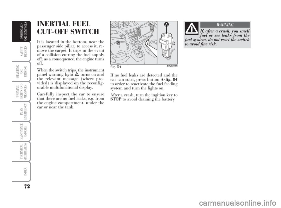
INERTIAL FUEL
CUT-OFF SWITCH
It is located in the bottom, near the
passenger side pillar; to access it, re-
move the carpet. It trips in the event
of a collision cutting the fuel supply
off; as a consequence, the engine turns
off.
When the switch trips, the instrument
panel warning light
èturns on and
the relevant message (where pro-
vided) is displayed on the reconfig-
urable multifunctional display.
Carefully inspect the car to ensure
that there are no fuel leaks, e.g. from
the engine compartment, under the
car or near the tank.
If, after a crash, you smell
fuel or see leaks from the
fuel system, do not reset the switch
to avoid fine risk.
WARNING
fig. 84L0D0388m
If no fuel leaks are detected and the
car can start, press button A-fig. 84
in order to reactivate the fuel feeding
system and turn the lights on.
After a crash, turn the ingition key to
STOPto avoid draining the battery.
038-094 MUSA 1ed GB 11-07-2008 14:10 Pagina 72
Page 77 of 218
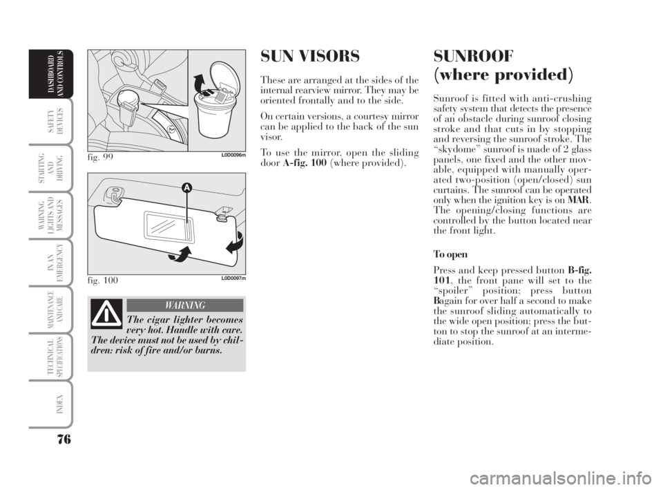
SUN VISORS
These are arranged at the sides of the
internal rearview mirror. They may be
oriented frontally and to the side.
On certain versions, a courtesy mirror
can be applied to the back of the sun
visor.
To use the mirror, open the sliding
doorA-fig. 100(where provided).
SUNROOF
(where provided)
Sunroof is fitted with anti-crushing
safety system that detects the presence
of an obstacle during sunroof closing
stroke and that cuts in by stopping
and reversing the sunroof stroke. The
“skydome” sunroof is made of 2 glass
panels, one fixed and the other mov-
able, equipped with manually oper-
ated two-position (open/closed) sun
curtains. The sunroof can be operated
only when the ignition key is on MAR.
The opening/closing functions are
controlled by the button located near
the front light.
To open
Press and keep pressed button B-fig.
101, the front pane will set to the
“spoiler” position; press button
Bagain for over half a second to make
the sunroof sliding automatically to
the wide open position; press the but-
ton to stop the sunroof at an interme-
diate position.
76
SAFETY
DEVICES
STARTING
AND
DRIVING
WARNING
LIGHTS AND
MESSAGES
IN AN
EMERGENCY
MAINTENANCE
AND CARE
TECHNICALSPECIFICATIONS
INDEX
DASHBOARD
AND CONTROLS
fig. 99L0D0096m
fig. 100L0D0097m
The cigar lighter becomes
very hot. Handle with care.
The device must not be used by chil-
dren: risk of fire and/or burns.
WARNING
038-094 MUSA 1ed GB 11-07-2008 14:10 Pagina 76