ESP Lancia Musa 2010 Owner handbook (in English)
[x] Cancel search | Manufacturer: LANCIA, Model Year: 2010, Model line: Musa, Model: Lancia Musa 2010Pages: 218, PDF Size: 3.71 MB
Page 101 of 218
100
STARTING
AND DRIVING
WARNING
LIGHTS AND
MESSAGES
IN AN
EMERGENCY
MAINTENANCE
AND CARE
TECHNICAL
SPECIFICA-
TIONS
INDEX
DASHBOARD
AND
CONTROLS
SAFETY
LOAD LIMITERS
To increase passenger’s safety, the
front seat belt reels contain a load
limiter which allows controlled sag in
such a way as to dose the force acting
on the chest and shoulders during the
belt restraining action in case of front
crash.GENERAL INSTRUCTIONS FOR
USING THE SEAT BELTS
The driver is responsible for respect-
ing and ensuring that all the other oc-
cupants of the car also respect the lo-
cal laws in force in relation to the use
of seat belts. Always fasten the seat
belts before starting off.
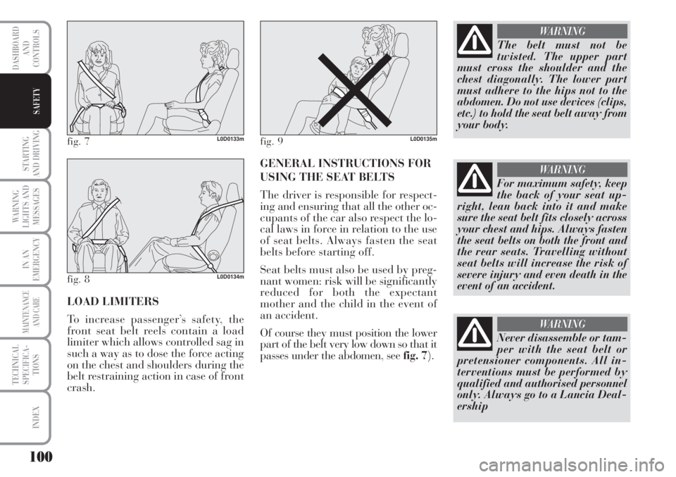
Seat belts must also be used by preg-
nant women: risk will be significantly
reduced for both the expectant
mother and the child in the event of
an accident.
Of course they must position the lower
part of the belt very low down so that it
passes under the abdomen, see fig. 7).
fig. 7L0D0133m
fig. 8L0D0134m
fig. 9L0D0135m
The belt must not be
twisted. The upper part
must cross the shoulder and the
chest diagonally. The lower part
must adhere to the hips not to the
abdomen. Do not use devices (clips,
etc.) to hold the seat belt away from
your body.
WARNING
Never disassemble or tam-
per with the seat belt or
pretensioner components. All in-
terventions must be performed by
qualified and authorised personnel
only. Always go to a Lancia Deal-
ership
WARNING
For maximum safety, keep
the back of your seat up-
right, lean back into it and make
sure the seat belt fits closely across
your chest and hips. Always fasten
the seat belts on both the front and
the rear seats. Travelling without
seat belts will increase the risk of
severe injury and even death in the
event of an accident.
WARNING
Page 104 of 218
103
STARTING
AND DRIVING
WARNING
LIGHTS AND
MESSAGES
IN AN
EMERGENCY
MAINTENANCE
AND CARE
TECHNICAL
SPECIFICA-
TIONS
INDEX
DASHBOARD
AND
CONTROLS
SAFETY
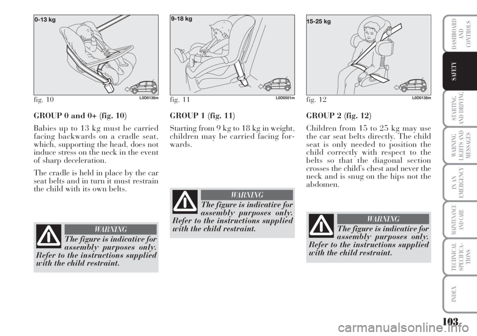
GROUP 0 and 0+ (fig. 10)
Babies up to 13 kg must be carried
facing backwards on a cradle seat,
which, supporting the head, does not
induce stress on the neck in the event
of sharp deceleration.
The cradle is held in place by the car
seat belts and in turn it must restrain
the child with its own belts.GROUP 1 (fig. 11)
Starting from 9 kg to 18 kg in weight,
children may be carried facing for-
wards.
fig. 11L0D0501mfig. 12L0D0138mfig. 10L0D0136m
The figure is indicative for
assembly purposes only.
Refer to the instructions supplied
with the child restraint.
WARNING
The figure is indicative for
assembly purposes only.
Refer to the instructions supplied
with the child restraint.
WARNING
GROUP 2 (fig. 12)
Children from 15 to 25 kg may use
the car seat belts directly. The child
seat is only needed to position the
child correctly with respect to the
belts so that the diagonal section
crosses the child’s chest and never the
neck and is snug on the hips not the
abdomen.
The figure is indicative for
assembly purposes only.
Refer to the instructions supplied
with the child restraint.
WARNING
Page 109 of 218
108
STARTING
AND DRIVING
WARNING
LIGHTS AND
MESSAGES
IN AN
EMERGENCY
MAINTENANCE
AND CARE
TECHNICAL
SPECIFICA-
TIONS
INDEX
DASHBOARD
AND
CONTROLS
SAFETY
FRONT AIRBAGS
The car is provided with front airbags
for the driver and passenger and win-
dow bags (head protection system). It
may be provided with optional front
side bags.
The front driver / passenger air bags
have been designed to protect the oc-
cupants in the event of head-on
crashes of medium-high severity, by
placing the cushion between the oc-
cupant and the steering wheel or
dashboard.
Front air bags are designed to protect
car’s occupants in front crashes and
therefore non-activation in other types
of collisions (side collisions, rear
shunts, roll-overs, etc.) is not a system
malfunction.
An electronic control unit will make
the bag inflate in the event of a frontal
crash.
The bag will inflate instantaneously
placing itself between the front occu-
pant’s body and the structures which
could cause injury. It will deflate im-
mediately afterwards.
Driver and passenger front airbags are
not a replacement of but complemen-
tary to the belts, which you are rec-
ommended to always wear, as speci-
fied by law in Europe and most non-
European countries.In the event of a collision, a person
not wearing a seat belt may be thrown
forward and con into contact with the
bag before it has fully opened. The
protection offered by the cushion is
reduced in such a case.
Front air bag may not be activated in
the following situations:
❒in collisions against highly de-
formable objects not affecting the
car front surface (e.g. bumper col-
lision against guard rail, etc.);
❒jamming of the car underneath
other vehicles or protective barri-
ers (e.g. underneath a truck or a
guard rail); in this case, the bags
would offer no additional protec-
tion with respect to the seat belt
and their deployment is unneces-
sary. No deployment in such cases
is consequently not the sign of a
fault.
The front airbags (driver and passen-
ger) are designed and calibrated to
protect front seat occupants who are
wearing seat belts. The volume of
front air bags at max. inflation fills
most of the space between the steer-
ing wheel and the driver and between
the dashboard and the passenger.FRONT AIR BAG ON DRIVER’S
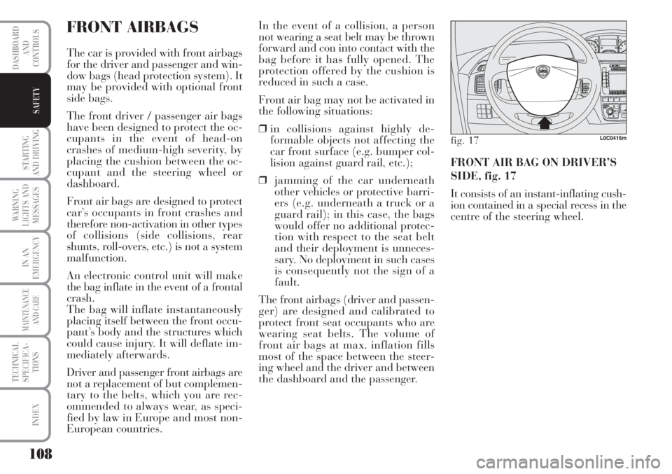
SIDE, fig. 17
It consists of an instant-inflating cush-
ion contained in a special recess in the
centre of the steering wheel.
fig. 17L0C0416m
Page 116 of 218
115
WARNING
LIGHTS AND
MESSAGES
IN AN
EMERGENCY
MAINTENANCE
AND CARE
TECHNICAL
SPECIFICA-
TIONS
INDEX
DASHBOARD
AND
CONTROLS
SAFETY
STARTING
AND DRIVING
❒will light up on the instrument
panel; wait for warning lights
Yand
mto go out. This will hap-
pen faster when the engine is
warm;
❒press the clutch pedal all the way
down without touching the accel-
erator;
❒turn the ignition key to AV Vas
soon as the warning light
mturns
off. Waiting too long will waste the
work done by the glow plugs. Re-
lease the key as soon as the engine
starts.
IMPORTANT With the engine cold,
the accelerator must be entirely re-
leased when turning the ignition key
to position AV V.
If the engine does not start at the first
attempt, return the ignition key to
STOP before repeating starting.
If, when the ignition key is at MAR,
the instrument panel warning light
Yremains lit, turn the key to STOP
and then back to MAR; if the warn-
ing lights remain on, try with the
other keys provided with the car.
Contact a Lancia Dealership if you
still cannot start the engine.HOW TO WARM UP THE
ENGINE AFTER IT HAS JUST
STARTED (petrol and Multijet
engines)
Proceed as follows:
❒drive off slowly, letting the engine
turn at medium speed. Accelerate
smoothly;
❒do not demand maximum perfor-
mance for the first few kilometres.
Wait until the engine coolant gauge
starts moving.Warning light
mwill
blink for 60 seconds after
starting or during pro-
longed cranking to indicate
a fault to the glow plug heating sys-
tem. Use the car normally if the en-
gine starts and go to a Lancia Deal-
ership as soon as possible.
STOPPING THE ENGINE
Turn the ignition to STOPwhile the en-
gine is idling.
IMPORTANT After a taxing drive,
you should allow the engine to “catch
its breath” before turning it off by let-
ting it idle to allow the temperature in
the engine compartment to fall.
Never jump start the engine
by pushing, towing or dri-
ving downhill. This could
cause a flow of fuel into the
catalytic converter and damage it
beyond repair.
A quick burst on the accel-
erator before turning off the
engine serves absolutely no
practical purpose, it wastes
fuel and is damaging especially to
turbocharged engines.
IMPORTANT Never leave the ignition
key to MARwhen the engine is off.
Page 119 of 218
118
WARNING
LIGHTS AND
MESSAGES
IN AN
EMERGENCY
MAINTENANCE
AND CARE
TECHNICAL
SPECIFICA-
TIONS
INDEX
DASHBOARD
AND
CONTROLS
SAFETY
STARTING
AND DRIVING
CONTAINING
RUNNING COSTS
Here are some suggestions which may
help you to keep the running costs of
your vehicle down and lower the
amount of toxic emissions released
into the atmosphere.
GENERAL CONSIDERATIONS
Car maintenance
Have checks and adjustments carried
out in accordance with the “Service
schedule”.
Ty r e s
Check tyre pressure regularly at least
once every four weeks: excessively low
pressure will increase consumption
because rolling resistance will be
higher.
Unnecessary loads
Do not travel with an overloaded
boot. The weight of the car (especially
when driving in town) and its trim
greatly affects consumption and sta-
bility.Roof rack/ski rack
Remove the roof rack or the ski rack
from the roof after use. These acces-
sories decrease aerodynamic penetra-
tion of the car and have a negative ef-
fect on consumption. It is better to use
a trailer to transport particularly
bulky objects.
Electric devices
Use electric devices only for the
amount of time needed. Rear heated
window, additional headlights, wind-
screen wipers and heater fan need a
considerable amount of energy, there-
fore increasing the requirement of
current increases fuel consumption
(up to +25% in the urban cycle).
Climate control
The climate control system requires
higher fuel consumption (up to +20%
in average): use the air vents when the
external temperature allows to.
Spoilers
The use of non-certified aerodynamic
items may adversely affect air drag
and fuel consumption levels.DRIVING STYLE
Starting
Do not warm the engine up with the
car standing: the engine warms up
very slowly in these conditions, in-
creasing consumption and emissions.
It is advisable to start off immediately
and slowly keeping the engine speed
down: the engine will warm up much
faster this way.
Unnecessary actions
Avoid revving up when starting at
traffic lights or before stopping the
engine. The latter action, like dou-
bling the clutch, is unnecessary and
causes increase of consumption and
pollution.
Gear selection
Use a higher gear as soon as traffic
and road conditions allow. Using a
low gear for faster acceleration will in-
crease consumption.
In the same way improper use of a
high gear increases consumption,
emissions an engine wear.
Page 121 of 218
120
WARNING
LIGHTS AND
MESSAGES
IN AN
EMERGENCY
MAINTENANCE
AND CARE
TECHNICAL
SPECIFICA-
TIONS
INDEX
DASHBOARD
AND
CONTROLS
SAFETY
STARTING
AND DRIVING
The weight of the trailer on the car’s
tow hitch will reduce the loading ca-
pacity of the car by the same amount.
Consider the weight of the car at full
load, including accessories and luggage
to make sure you do not exceed the
maximum towable weight (shown on
the log book).
Respect the speed limits specific for
each country for vehicles towing trail-
ers. In all cases, the top speed must
not exceed 100 km/h.
The ABS with which the
car may be equipped will
not control the braking system of
the trailer. Particular caution is
required on slippery roads.
WARNING
Never modify the braking
system of the car to control
the trailer brake. The trailer brak-
ing system must be fully indepen-
dent from the hydraulic system of
the car.
WARNING
INSTALLING THE TOW HOOK
The towing device should be fastened
to the body by specialised personnel
according to any additional and/or in-
tegrative information supplied by the
Manufacturer of the device.
The towing device must meet current
regulations with reference to
94/20/EC Directive and subsequent
amendments.
For any version the towing device
used must match the towable weight
of the car on which it is to be in-
stalled.
For the electric connection a unified
connector should be used which is
generally placed on a special bracket
normally fastened to the towing de-
vice, and a special ECU for external
trailer light control shall be installed
on the car. For the electric connection, 7 or 13
pin 12VDC connection is to be used
(CUNA/UNI and ISO/DIN Stan-
dards). Follow the instructions pro-
vided by the car manufacturer and/or
the tow hitch manufacturer.
An electric brake should be supplied
directly by the battery through a ca-
ble with a cross section of no less than
2.5 mm2,5.
IMPORTANT Electric brake or other
device shall be used with running en-
gine.
In addition to the electric branches,
the car’s electric system can only be
connected to the supply cable for an
electric brake and to the cable for an
internal light, though not above 15W.
For connections use the preset control
unit with battery cable no less than
2.5 mm
2.
Page 123 of 218
122
WARNING
LIGHTS AND
MESSAGES
IN AN
EMERGENCY
MAINTENANCE
AND CARE
TECHNICAL
SPECIFICA-
TIONS
INDEX
DASHBOARD
AND
CONTROLS
SAFETY
STARTING
AND DRIVING
SNOW TYRES
Use snow tyres of the same size as the
normal tyres provided with the car.
Lancia Dealership will be happy to
provide advice concerning the most
suitable type of tyre for the customer’s
requirements.
For the type of tyre to be used, infla-
tion pressures and the specifications
of snow tyres, follow the instructions
given in paragraph “Wheels” in sec-
tion “Technical specifications”.
The performance of these tyres is con-
siderably reduced when the tread
depth is less than 4 mm. Replace
them in this case.Due to their specific features, the per-
formance of snow tyres is much lower
than that of normal types in normal
conditions or long motorway
stretches. Limit performance accord-
ing the use for which they were ap-
proved.
IMPORTANT When snow tyres are
used with a max speed index below
the one that can be reached by the car
(increased by 5%), place a notice in
the passenger’s compartment, plainly
in the driver’s view which states the
max permissible speed of the snow
tyres (as per EC Directive).
All four tyres should be the same
(brand and track) to ensure greater
safety when driving and braking and
better driveability.
Remember that it is inappropriate to
change the direction of rotation of
tyres.The top speed of a “T”
type snow tyre is 190
km/h. Respect the highway code in
all cases.
WARNING
Page 135 of 218
134
IN AN
EMERGENCY
MAINTENANCE
AND CARE
TECHNICAL
SPECIFICA-
TIONS
INDEX
DASHBOARD
AND
CONTROLS
SAFETY
STARTING
AND DRIVING
WARNING
LIGHTS AND
MESSAGES
LEFT-HAND
DIRECTION
INDICATOR
(green - blinking)
The warning light turns on when the
direction indicator control lever is
moved downwards or, together with
the right indicator, when the hazard
warning light button is pressed.
F
RIGHT-HAND
DIRECTION
INDICATOR
(green - blinking)
The warning light turns on when the
direction indicator control lever is
moved upwards or, together with the
left indicator, when the hazard warn-
ing light button is pressed.
D
“DUALDRIVE”
ELECTRIC POWER
STEERING SYSTEM ON
(symbol on display)
The message CITY lights up on the
display when the “Dualdrive” electric
power steering system is turned on by
pressing the corresponding control
button. Press the button again to turn
the CITY indication off.
CITY
CRUISE CONTROL
(green)
(for versions/markets,
where provided)
When the ignition key is moved to
MAR, the warning light turns on and
should go off after a few seconds.
The warning light is lit up on the dis-
play by rotating the Cruise Control se-
lector wheel to ON.
The display will show the dedicated
message.
Ü
MAIN BEAM
HEADLIGHTS (blue)
The warning light turns on
when the main beams are
turned on.
POSSIBLE ICE ON ROAD
When the external temperature reaches
or drops under 3 °C, to indicate the
possible presence of ice on the road.
Symbol
❄ will appear on the display,
with a warning message and the tem-
perature indication will start blinking.
1
LIMITED RANGE
A message will appear on the display
to inform the driver that the remain-
ing range is less than 50 kilometres
(30 miles) or that there are less than
4 litres of fuel in the tank.
Page 147 of 218
146
WARNING
LIGHTS AND
MESSAGES
MAINTENANCE
AND CARE
TECHNICAL
SPECIFICA-
TIONS
INDEX
DASHBOARD
AND
CONTROLS
SAFETY
STARTING
AND DRIVING
IN AN
EMERGENCY
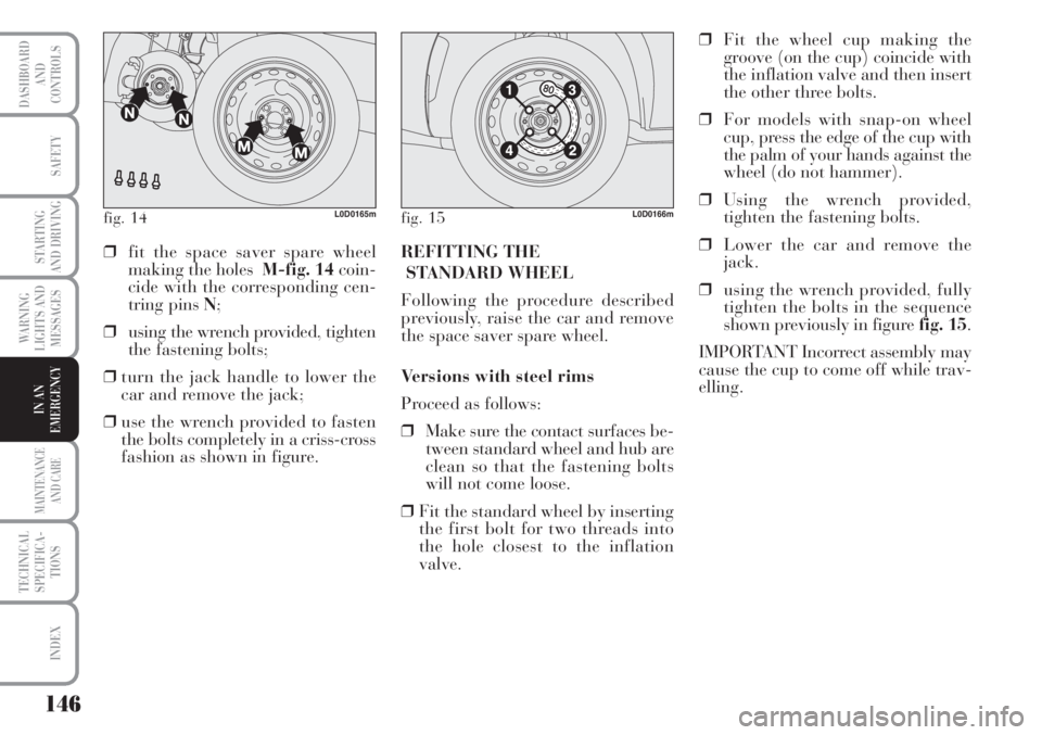
fig. 14L0D0165mfig. 15L0D0166m
❒fit the space saver spare wheel
making the holes M-fig. 14coin-
cide with the corresponding cen-
tring pins N;
❒using the wrench provided, tighten
the fastening bolts;
❒turn the jack handle to lower the
car and remove the jack;
❒use the wrench provided to fasten
the bolts completely in a criss-cross
fashion as shown in figure. REFITTING THE
STANDARD WHEEL
Following the procedure described
previously, raise the car and remove
the space saver spare wheel.
Versions with steel rims
Proceed as follows:
❒Make sure the contact surfaces be-
tween standard wheel and hub are
clean so that the fastening bolts
will not come loose.
❒Fit the standard wheel by inserting
the first bolt for two threads into
the hole closest to the inflation
valve.❒Fit the wheel cup making the
groove (on the cup) coincide with
the inflation valve and then insert
the other three bolts.
❒For models with snap-on wheel
cup, press the edge of the cup with
the palm of your hands against the
wheel (do not hammer).
❒Using the wrench provided,
tighten the fastening bolts.
❒Lower the car and remove the
jack.
❒using the wrench provided, fully
tighten the bolts in the sequence
shown previously in figure fig. 15.
IMPORTANT Incorrect assembly may
cause the cup to come off while trav-
elling.
Page 148 of 218
147
WARNING
LIGHTS AND
MESSAGES
MAINTENANCE
AND CARE
TECHNICAL
SPECIFICA-
TIONS
INDEX
DASHBOARD
AND
CONTROLS
SAFETY
STARTING
AND DRIVING
IN AN
EMERGENCY
Versions with alloy rims
❒Check that the hub contact sur-
faces are clean;
❒fit the normal wheel centring it on
the pins, lead in the fastening
screws and tighten them using the
wrench provided;
❒lower the car and remove the jack;
❒using the wrench provided, fully
tighten the bolts in the sequence
shown in fig. 15.
❒snap fit the wheel cup on the hub.When you have finished
❒stow the spare wheel in the space
provided in the boot;
❒fit the jack partially open in its
box forcing it lightly to prevent it
from vibrating when travelling;
❒put the tools back into their places
in the container;
❒arrange the container and tools in
the spare wheel and secure the fas-
tening device;
❒rearrange the preformed boot
cover correctly. WHEN NEEDING
TO CHANGE A
BULB
GENERAL INSTRUCTIONS
❒When a bulb is not working, check
that the corresponding fuse is in-
tact before replacing it: refer to the
“If a fuse blows” paragraph in this
chapter for fuse location.
❒before changing a bulb check the
contacts for oxidation;
❒burnt bulbs must be replaced by
others of the same type and power;
❒always check the height of the
headlight beam after changing a
bulb.
Halogen lamps must be
handled holding the metal-
lic part only. Touching the
transparent part of the bulb
with your fingers may reduce the in-
tensity of the emitted light and even
compromise duration of the lamp it-
self.