dashboard Lancia Musa 2010 Owner handbook (in English)
[x] Cancel search | Manufacturer: LANCIA, Model Year: 2010, Model line: Musa, Model: Lancia Musa 2010Pages: 218, PDF Size: 3.71 MB
Page 38 of 218
37
SAFETY
STARTING
AND DRIVING
WARNING
LIGHTS AND
MESSAGES
IN AN
EMERGENCY
MAINTENANCE
AND CARE
TECHNICAL
SPECIFICA-
TIONS
INDEX
DASHBOARD
AND
CONTROLS
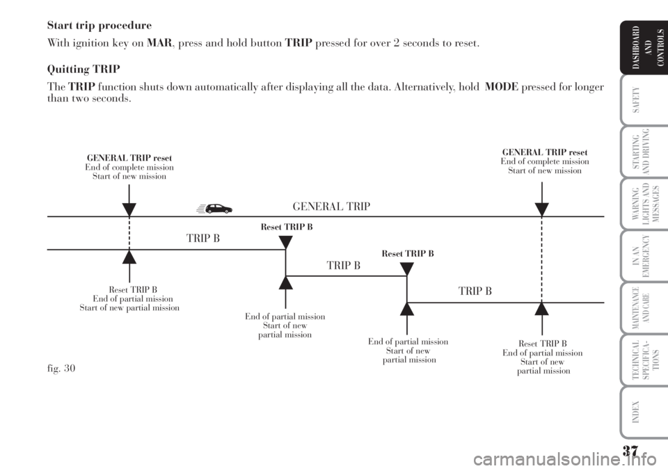
Start trip procedure
With ignition key on MAR, press and hold button TRIPpressed for over 2 seconds to reset.
Quitting TRIP
TheTRIPfunction shuts down automatically after displaying all the data. Alternatively, hold MODEpressed for longer
than two seconds.
Reset TRIP B
End of partial mission
Start of new partial mission
End of partial mission
Start of new
partial mission
Reset TRIP B
End of partial mission
Start of new
partial mission GENERAL TRIP reset
End of complete mission
Start of new mission GENERAL TRIP reset
End of complete mission
Start of new mission
End of partial mission
Start of new
partial mission Reset TRIP B
Reset TRIP B
TRIP B
TRIP B
TRIP B GENERAL TRIP
˙
˙
˙
˙
˙
˙˙
˙
fig. 30
Page 39 of 218
38
SAFETY
STARTING
AND DRIVING
WARNING
LIGHTS AND
MESSAGES
IN AN
EMERGENCY
MAINTENANCE
AND CARE
TECHNICAL
SPECIFICA-
TIONS
INDEX
DASHBOARD
AND
CONTROLS
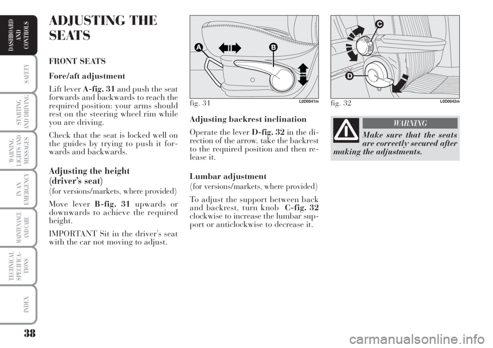
Adjusting backrest inclination
Operate the lever D-fig. 32in the di-
rection of the arrow, take the backrest
to the required position and then re-
lease it.
Lumbar adjustment
(for versions/markets, where provided)
To adjust the support between back
and backrest, turn knob C-fig. 32
clockwise to increase the lumbar sup-
port or anticlockwise to decrease it.
ADJUSTING THE
SEATS
FRONT SEATS
Fore/aft adjustment
Lift lever A-fig. 31and push the seat
forwards and backwards to reach the
required position: your arms should
rest on the steering wheel rim while
you are driving.
Check that the seat is locked well on
the guides by trying to push it for-
wards and backwards.
Adjusting the height
(driver’s seat)
(for versions/markets, where provided)
Move lever B-fig. 31upwards or
downwards to achieve the required
height.
IMPORTANT Sit in the driver’s seat
with the car not moving to adjust.
fig. 31L0D0041mfig. 32L0D0042m
Make sure that the seats
are correctly secured after
making the adjustments.
WARNING
Page 40 of 218
39
SAFETY
STARTING
AND DRIVING
WARNING
LIGHTS AND
MESSAGES
IN AN
EMERGENCY
MAINTENANCE
AND CARE
TECHNICAL
SPECIFICA-
TIONS
INDEX
DASHBOARD
AND
CONTROLS
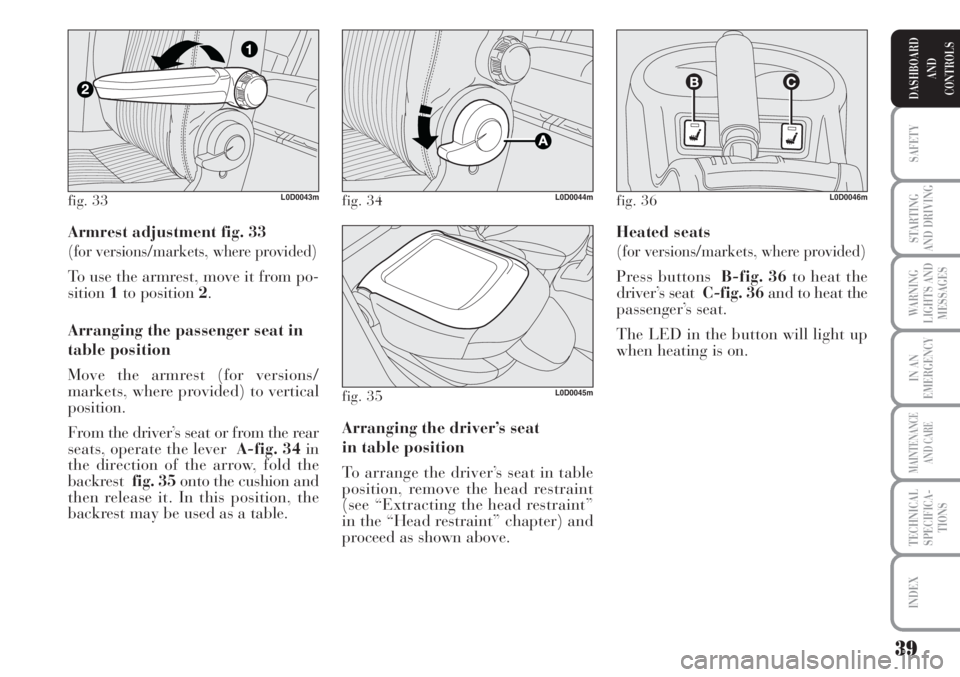
Armrest adjustment fig. 33
(for versions/markets, where provided)
To use the armrest, move it from po-
sition1to position 2.
Arranging the passenger seat in
table position
Move the armrest (for versions/
markets, where provided) to vertical
position.
From the driver’s seat or from the rear
seats, operate the lever A-fig. 34in
the direction of the arrow, fold the
backrest fig. 35onto the cushion and
then release it. In this position, the
backrest may be used as a table. Heated seats
(for versions/markets, where provided)
Press buttons B-fig. 36to heat the
driver’s seat C-fig. 36and to heat the
passenger’s seat.
The LED in the button will light up
when heating is on.
Arranging the driver’s seat
in table position
To arrange the driver’s seat in table
position, remove the head restraint
(see “Extracting the head restraint”
in the “Head restraint” chapter) and
proceed as shown above.
fig. 33L0D0043mfig. 34L0D0044m
fig. 35L0D0045m
fig. 36L0D0046m
Page 41 of 218
40
SAFETY
STARTING
AND DRIVING
WARNING
LIGHTS AND
MESSAGES
IN AN
EMERGENCY
MAINTENANCE
AND CARE
TECHNICAL
SPECIFICA-
TIONS
INDEX
DASHBOARD
AND
CONTROLS
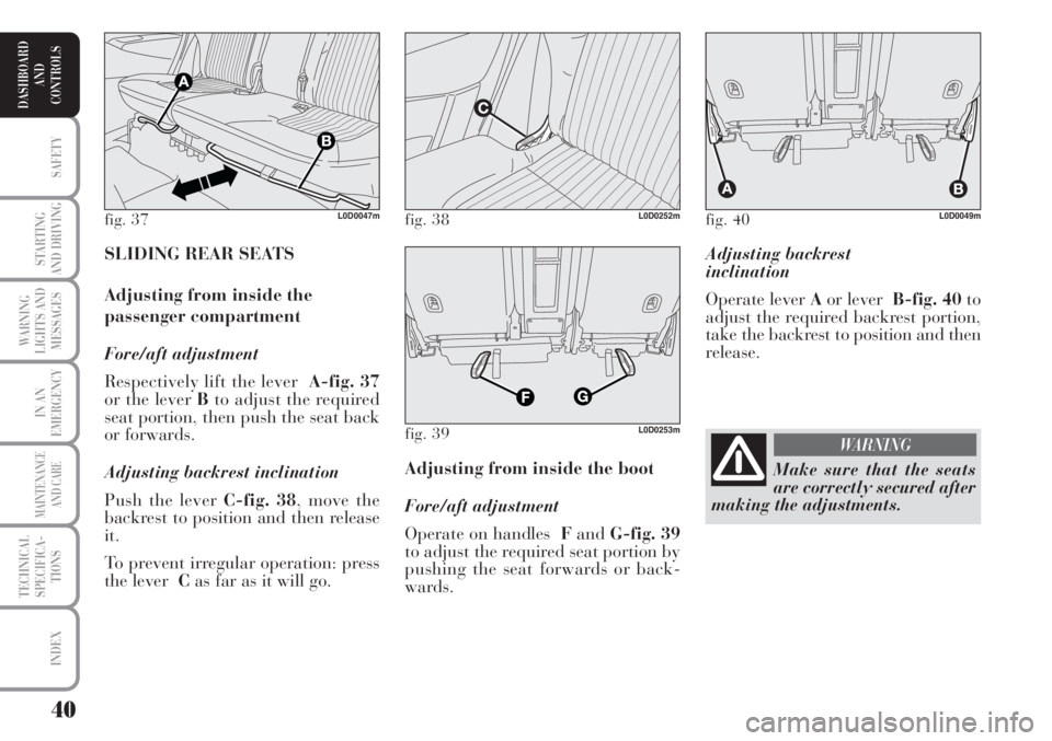
Adjusting backrest
inclination
Operate lever Aor leverB-fig. 40to
adjust the required backrest portion,
take the backrest to position and then
release.
Adjusting from inside the boot
Fore/aft adjustment
Operate on handles FandG-fig. 39
to adjust the required seat portion by
pushing the seat forwards or back-
wards. SLIDING REAR SEATS
Adjusting from inside the
passenger compartment
Fore/aft adjustment
Respectively lift the lever A-fig. 37
or the lever Bto adjust the required
seat portion, then push the seat back
or forwards.
Adjusting backrest inclination
Push the lever C-fig. 38, move the
backrest to position and then release
it.
To prevent irregular operation: press
the lever Cas far as it will go.
fig. 37L0D0047mfig. 38L0D0252m
fig. 39L0D0253m
fig. 40L0D0049m
Make sure that the seats
are correctly secured after
making the adjustments.
WARNING
Page 42 of 218
41
SAFETY
STARTING
AND DRIVING
WARNING
LIGHTS AND
MESSAGES
IN AN
EMERGENCY
MAINTENANCE
AND CARE
TECHNICAL
SPECIFICA-
TIONS
INDEX
DASHBOARD
AND
CONTROLS
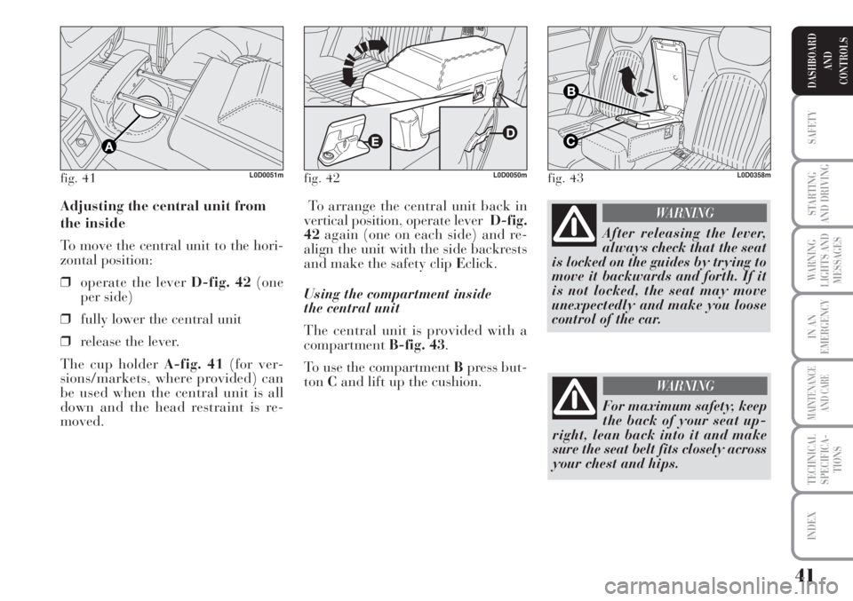
To arrange the central unit back in
vertical position, operate lever D-fig.
42again (one on each side) and re-
align the unit with the side backrests
and make the safety clip Eclick.
Using the compartment inside
the central unit
The central unit is provided with a
compartmentB-fig. 43.
To use the compartment Bpress but-
tonCand lift up the cushion. Adjusting the central unit from
the inside
To move the central unit to the hori-
zontal position:
❒operate the lever D-fig. 42(one
per side)
❒fully lower the central unit
❒release the lever.
The cup holder A-fig. 41(for ver-
sions/markets, where provided) can
be used when the central unit is all
down and the head restraint is re-
moved.
fig. 41L0D0051mfig. 42L0D0050mfig. 43L0D0358m
After releasing the lever,
always check that the seat
is locked on the guides by trying to
move it backwards and forth. If it
is not locked, the seat may move
unexpectedly and make you loose
control of the car.
WARNING
For maximum safety, keep
the back of your seat up-
right, lean back into it and make
sure the seat belt fits closely across
your chest and hips.
WARNING
Page 43 of 218
42
SAFETY
STARTING
AND DRIVING
WARNING
LIGHTS AND
MESSAGES
IN AN
EMERGENCY
MAINTENANCE
AND CARE
TECHNICAL
SPECIFICA-
TIONS
INDEX
DASHBOARD
AND
CONTROLS
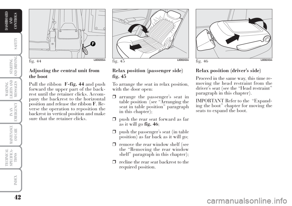
Relax position (driver’s side)
Proceed in the same way, this time re-
moving the head restraint from the
driver’s seat (see the “Head restraint”
paragraph in this chapter).
IMPORTANT Refer to the “Expand-
ing the boot” chapter for moving the
seats to expand the boot. Relax position (passenger side)
fig. 45
To arrange the seat in relax position,
with the door open:
❒arrange the passenger’s seat in
table position (see “Arranging the
seat in table position” paragraph
in this chapter);
❒push the rear seat forward as far
as it will go fig. 46;
❒push the passenger’s seat (in table
position) as far back as it will go;
❒remove the rear window shelf (see
the “Removing the rear window
shelf” paragraph in this chapter);
❒recline the rear seat backrest to the
required position. Adjusting the central unit from
the boot
Pull the ribbonF-fig. 44and push
forward the upper part of the back-
rest until the retainer clicks. Accom-
pany the backrest to the horizontal
position and release the ribbon F. Re-
verse the operation to reposition the
backrest in vertical position and make
sure that the retainer clicks.
fig. 44L0D0255mfig. 45L0D0242mfig. 46L0D0243m
Page 44 of 218
43
SAFETY
STARTING
AND DRIVING
WARNING
LIGHTS AND
MESSAGES
IN AN
EMERGENCY
MAINTENANCE
AND CARE
TECHNICAL
SPECIFICA-
TIONS
INDEX
DASHBOARD
AND
CONTROLS
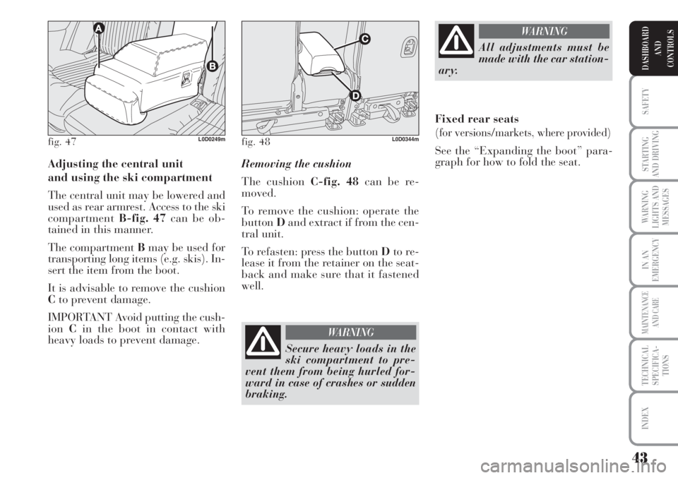
Adjusting the central unit
and using the ski compartment
The central unit may be lowered and
used as rear armrest. Access to the ski
compartmentB-fig. 47can be ob-
tained in this manner.
The compartment Bmay be used for
transporting long items (e.g. skis). In-
sert the item from the boot.
It is advisable to remove the cushion
Cto prevent damage.
IMPORTANT Avoid putting the cush-
ionCin the boot in contact with
heavy loads to prevent damage.Removing the cushion
The cushion C-fig. 48can be re-
moved.
To remove the cushion: operate the
buttonDand extract if from the cen-
tral unit.
To refasten: press the button Dto re-
lease it from the retainer on the seat-
back and make sure that it fastened
well.
fig. 47L0D0249mfig. 48L0D0344m
Secure heavy loads in the
ski compartment to pre-
vent them from being hurled for-
ward in case of crashes or sudden
braking.
WARNING
All adjustments must be
made with the car station-
ary.
WARNING
Fixed rear seats
(for versions/markets, where provided)
See the “Expanding the boot” para-
graph for how to fold the seat.
Page 45 of 218
44
SAFETY
STARTING
AND DRIVING
WARNING
LIGHTS AND
MESSAGES
IN AN
EMERGENCY
MAINTENANCE
AND CARE
TECHNICAL
SPECIFICA-
TIONS
INDEX
DASHBOARD
AND
CONTROLS
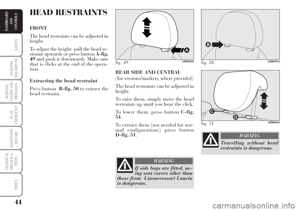
REAR SIDE AND CENTRAL
(for versions/markets, where provided)
The head restraints can be adjusted in
height.
To raise them, simply move the head
restraints up until you hear the click.
To lower them, press button C-fig.
51.
To extract them (not needed for nor-
mal configurations) press button
D-fig. 51.
HEAD RESTRAINTS
FRONT
The head restraints can be adjusted in
height.
To adjust the height: pull the head re-
straint upwards or press button A-fig.
49and push it downwards. Make sure
that is clicks at the end of the opera-
tion.
Extracting the head restraint
Press button B-fig. 50to extract the
head restraint.
fig. 49L0D0052mfig. 50L0D0237m
If side bags are fitted, us-
ing seat covers other than
those from Lineaccessori Lancia
is dangerous.
WARNING
fig. 51L0D0053m
Travelling without head
restraints is dangerous.
WARNING
Page 46 of 218
45
SAFETY
STARTING
AND DRIVING
WARNING
LIGHTS AND
MESSAGES
IN AN
EMERGENCY
MAINTENANCE
AND CARE
TECHNICAL
SPECIFICA-
TIONS
INDEX
DASHBOARD
AND
CONTROLS
ADJUSTING THE
STEERING WHEEL
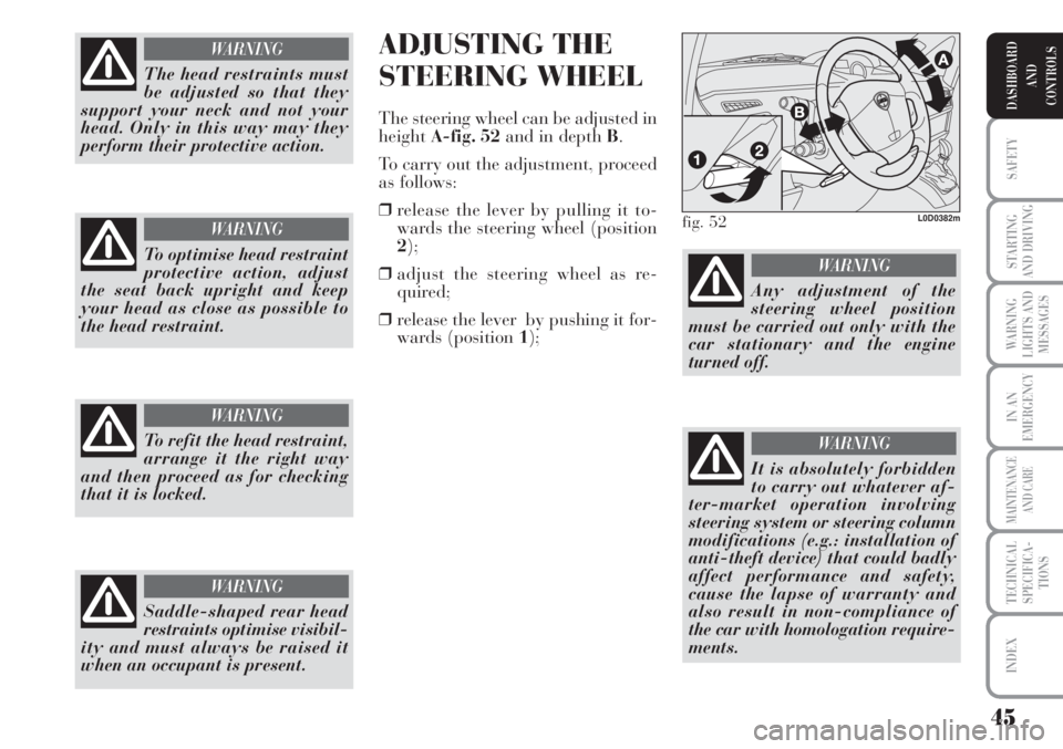
The steering wheel can be adjusted in
heightA-fig. 52and in depth B.
To carry out the adjustment, proceed
as follows:
❒release the lever by pulling it to-
wards the steering wheel (position
2);
❒adjust the steering wheel as re-
quired;
❒release the lever by pushing it for-
wards (position 1);
Saddle-shaped rear head
restraints optimise visibil-
ity and must always be raised it
when an occupant is present.
WARNING
fig. 52L0D0382m
Any adjustment of the
steering wheel position
must be carried out only with the
car stationary and the engine
turned off.
WARNING
It is absolutely forbidden
to carry out whatever af-
ter-market operation involving
steering system or steering column
modifications (e.g.: installation of
anti-theft device) that could badly
affect performance and safety,
cause the lapse of warranty and
also result in non-compliance of
the car with homologation require-
ments.
WARNING
The head restraints must
be adjusted so that they
support your neck and not your
head. Only in this way may they
perform their protective action.
WARNING
To optimise head restraint
protective action, adjust
the seat back upright and keep
your head as close as possible to
the head restraint.
WARNING
To refit the head restraint,
arrange it the right way
and then proceed as for checking
that it is locked.
WARNING
Page 47 of 218
46
SAFETY
STARTING
AND DRIVING
WARNING
LIGHTS AND
MESSAGES
IN AN
EMERGENCY
MAINTENANCE
AND CARE
TECHNICAL
SPECIFICA-
TIONS
INDEX
DASHBOARD
AND
CONTROLS
Adjust with the vehicle stationary and
the handbrake applied.
The mirror demister will be turned on
automatically by the rear window
heater.
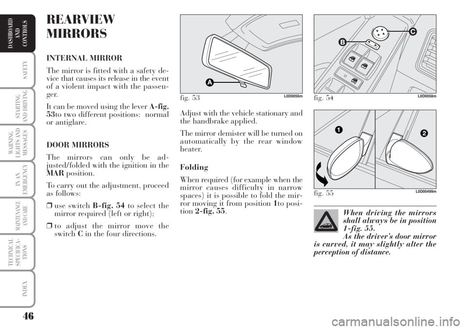
Folding
When required (for example when the
mirror causes difficulty in narrow
spaces) it is possible to fold the mir-
ror moving it from position 1to posi-
tion2-fig. 55.
REARVIEW
MIRRORS
INTERNAL MIRROR
The mirror is fitted with a safety de-
vice that causes its release in the event
of a violent impact with the passen-
ger.
It can be moved using the lever A-fig.
53to two different positions: normal
or antiglare.
DOOR MIRRORS
The mirrors can only be ad-
justed/folded with the ignition in the
MARposition.
To carry out the adjustment, proceed
as follows:
❒use switch B-fig. 54to select the
mirror required (left or right);
❒to adjust the mirror move the
switchCin the four directions.
fig. 53L0D0056m
When driving the mirrors
shall always be in position
1-fig. 55.
As the driver’s door mirror
is curved, it may slightly alter the
perception of distance.
fig. 54L0D0058m
fig. 55L0D00499m