key Lancia Musa 2011 Owner handbook (in English)
[x] Cancel search | Manufacturer: LANCIA, Model Year: 2011, Model line: Musa, Model: Lancia Musa 2011Pages: 218, PDF Size: 3.91 MB
Page 64 of 218
63
SAFETY
STARTING
AND DRIVING
WARNING
LIGHTS AND
MESSAGES
IN AN
EMERGENCY
MAINTENANCE
AND CARE
TECHNICAL
SPECIFICA-
TIONS
INDEX
DASHBOARD
AND
CONTROLS
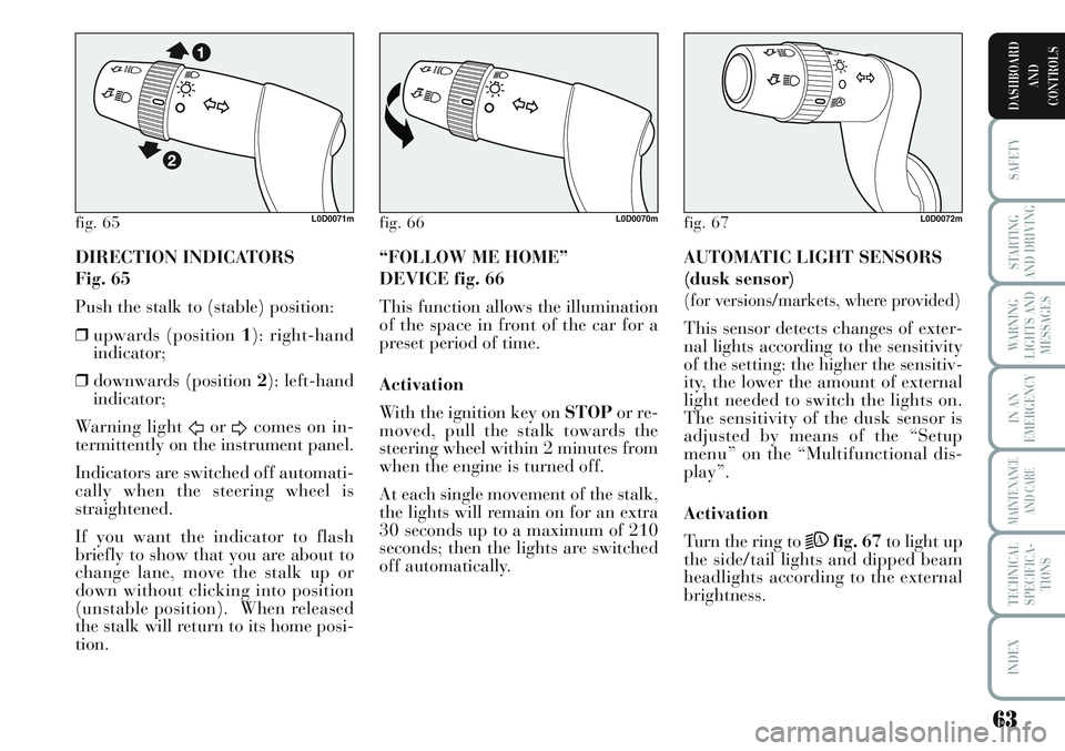
DIRECTION INDICATORS
Fig. 65
Push the stalk to (stable) position:
❒upwards (position 1): right-hand
indicator;
❒downwards (position 2): left-hand
indicator;
Warning light
ForDcomes on in-
termittently on the instrument panel.
Indicators are switched off automati-
cally when the steering wheel is
straightened.
If you want the indicator to flash
briefly to show that you are about to
change lane, move the stalk up or
down without clicking into position
(unstable position). When released
the stalk will return to its home posi-
tion.AUTOMATIC LIGHT SENSORS
(dusk sensor)
(for versions/markets, where provided)
This sensor detects changes of exter-
nal lights according to the sensitivity
of the setting: the higher the sensitiv-
ity, the lower the amount of external
light needed to switch the lights on.
The sensitivity of the dusk sensor is
adjusted by means of the “Setup
menu” on the “Multifunctional dis-
play”.
Activation
Turn the ring to
2Afig. 67to light up
the side/tail lights and dipped beam
headlights according to the external
brightness. “FOLLOW ME HOME”
DEVICE fig. 66
This function allows the illumination
of the space in front of the car for a
preset period of time.
Activation
With the ignition key on STOPor re-
moved, pull the stalk towards the
steering wheel within 2 minutes from
when the engine is turned off.
At each single movement of the stalk,
the lights will remain on for an extra
30 seconds up to a maximum of 210
seconds; then the lights are switched
off automatically.
fig. 65L0D0071mfig. 66L0D0070mfig. 67L0D0072m
Page 65 of 218
64
SAFETY
STARTING
AND DRIVING
WARNING
LIGHTS AND
MESSAGES
IN AN
EMERGENCY
MAINTENANCE
AND CARE
TECHNICAL
SPECIFICA-
TIONS
INDEX
DASHBOARD
AND
CONTROLS
CLEANING THE
WINDOWS
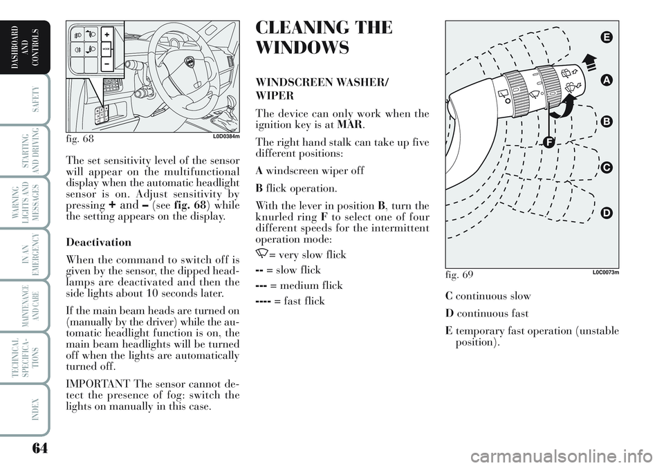
WINDSCREEN WASHER/
WIPER
The device can only work when the
ignition key is at MAR.
The right hand stalk can take up five
different positions:
Awindscreen wiper off
Bflick operation.
With the lever in position B, turn the
knurled ring Fto select one of four
different speeds for the intermittent
operation mode:
,= very slow flick
--= slow flick
---= medium flick
----= fast flick The set sensitivity level of the sensor
will appear on the multifunctional
display when the automatic headlight
sensor is on. Adjust sensitivity by
pressing
+and–(seefig. 68) while
the setting appears on the display.
Deactivation
When the command to switch off is
given by the sensor, the dipped head-
lamps are deactivated and then the
side lights about 10 seconds later.
If the main beam heads are turned on
(manually by the driver) while the au-
tomatic headlight function is on, the
main beam headlights will be turned
off when the lights are automatically
turned off.
IMPORTANT The sensor cannot de-
tect the presence of fog: switch the
lights on manually in this case.
fig. 68L0D0384m
fig. 69L0C0073m
Ccontinuous slow
Dcontinuous fast
Etemporary fast operation (unstable
position).
Page 67 of 218
66
SAFETY
STARTING
AND DRIVING
WARNING
LIGHTS AND
MESSAGES
IN AN
EMERGENCY
MAINTENANCE
AND CARE
TECHNICAL
SPECIFICA-
TIONS
INDEX
DASHBOARD
AND
CONTROLS
❒in synchronous mode (at half the
frequency of the windscreen
wiper) when the windscreen wiper
is running.
The rear window wiper will run in
continuous mode when the wind-
screen wiper is running and reverse
gear is engaged.
Pull the stalk towards the dashboard
(unstable position) to operate the rear
window washer.
Hold the stalk pushed for longer than
half a second to operate the rear win-
dow wiper as well.
Smart wash function is activated as
for the windscreen wiper when the
stalk is released. The wiper will flick once to indicate
that the sensor has been reactivated.
The rain sensor is able to recognize
and automatically adjust itself in the
presence of the following particular
conditions:
❒dirt on the controlled surface (salt,
dirt, etc.);
❒difference between day and night.
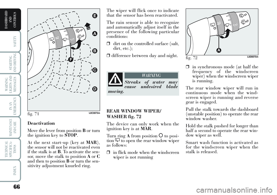
Deactivation
Move the lever from position Bor turn
the ignition key to STOP.
At the next start-up (key at MAR),
the sensor will not be reactivated even
if the stalk is at B. To activate the sen-
sor, move the stalk to position AorC
and then to position Bor turn the sen-
sitivity adjustment knurled ring.
fig. 71L0C0073m
Streaks of water may
cause undesired blade
moving.
WARNING
REAR WINDOW WIPER/
WASHER fig. 72
The device can only work when the
ignition key is at MAR.
Turn ring Afrom position
åto posi-
tion'to open the rear window wiper
as follows:
❒in flick mode when the windscreen
wiper is not running
fig. 72L0D0075m
Page 69 of 218
68
SAFETY
STARTING
AND DRIVING
WARNING
LIGHTS AND
MESSAGES
IN AN
EMERGENCY
MAINTENANCE
AND CARE
TECHNICAL
SPECIFICA-
TIONS
INDEX
DASHBOARD
AND
CONTROLS
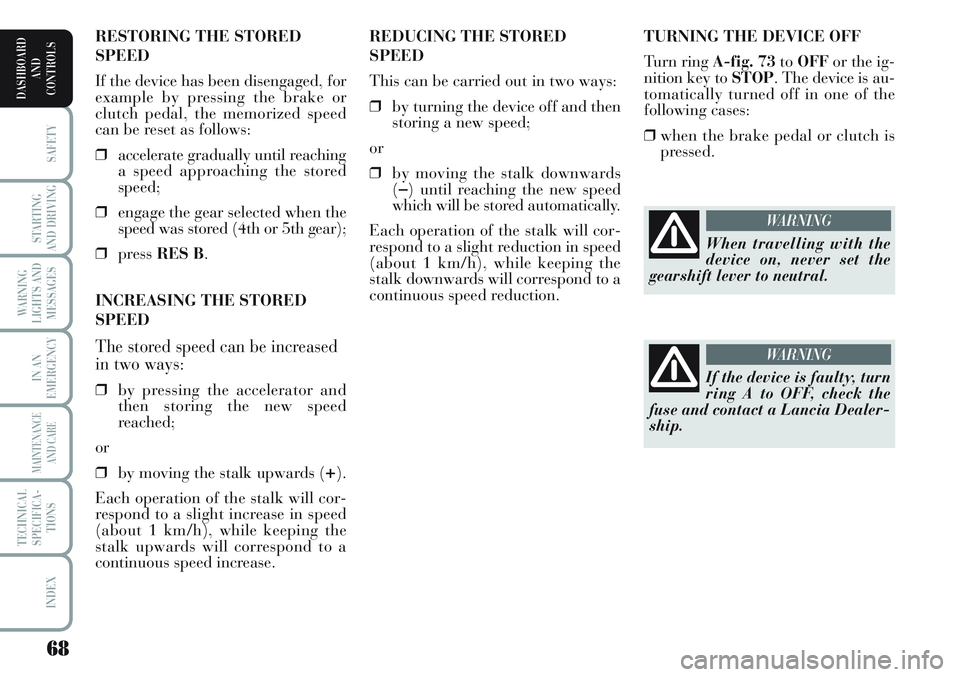
TURNING THE DEVICE OFF
Turn ring A-fig. 73toOFFor the ig-
nition key to STOP. The device is au-
tomatically turned off in one of the
following cases:
❒when the brake pedal or clutch is
pressed. REDUCING THE STORED
SPEED
This can be carried out in two ways:
❒by turning the device off and then
storing a new speed;
or
❒by moving the stalk downwards
(
–) until reaching the new speed
which will be stored automatically.
Each operation of the stalk will cor-
respond to a slight reduction in speed
(about 1 km/h), while keeping the
stalk downwards will correspond to a
continuous speed reduction. RESTORING THE STORED
SPEED
If the device has been disengaged, for
example by pressing the brake or
clutch pedal, the memorized speed
can be reset as follows:
❒accelerate gradually until reaching
a speed approaching the stored
speed;
❒engage the gear selected when the
speed was stored (4th or 5th gear);
❒press RES B.
INCREASING THE STORED
SPEED
The stored speed can be increased
in two ways:
❒by pressing the accelerator and
then storing the new speed
reached;
or
❒by moving the stalk upwards (
+).
Each operation of the stalk will cor-
respond to a slight increase in speed
(about 1 km/h), while keeping the
stalk upwards will correspond to a
continuous speed increase.
When travelling with the
device on, never set the
gearshift lever to neutral.
WARNING
If the device is faulty, turn
ring A to OFF, check the
fuse and contact a Lancia Dealer-
ship.
WARNING
Page 70 of 218
69
SAFETY
STARTING
AND DRIVING
WARNING
LIGHTS AND
MESSAGES
IN AN
EMERGENCY
MAINTENANCE
AND CARE
TECHNICAL
SPECIFICA-
TIONS
INDEX
DASHBOARD
AND
CONTROLS
CEILING LIGHTS
FRONT CEILING LIGHT
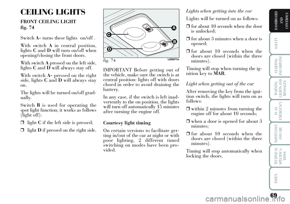
fig. 74
SwitchA-turns these lights on/off .
With switch Ain central position,
lightsCandDwill turn on/off when
opening/closing the front doors.
With switch Apressed on the left side,
lightsCandDwill always stay off.
With switch A-pressed on the right
side, lights CandDwill always stay
on.
The lights will be turned on/off grad-
ually.
SwitchBis used for operating the
spot light function; it works as follows
(light off):
❒lightCif the left side is pressed;
❒lightDif pressed on the right side.Lights when getting into the car
Lights will be turned on as follows:
❒for about 10 seconds when the door
is unlocked;
❒for about 3 minutes when a door is
opened;
❒for about 10 seconds when the
doors are closed (within the three
minutes).
Timing will stop when turning the ig-
nition key to MAR.
Light when getting out of the car
After removing the key from the igni-
tion switch, the lights will turn on as
follows:
❒within 2 minutes from turning the
engine off for about 10 seconds;
❒when a door is opened for about 3
minutes;
❒for about 10 seconds when the
doors are closed (within the three
minutes).
Timing will stop automatically when
locking the doors. IMPORTANT Before getting out of
the vehicle, make sure the switch is at
central position: lights off with doors
closed in order to avoid draining the
battery.
In any case, if the switch is left inad-
vertently to the on position, the lights
will turn off automatically 15 minutes
after turning the engine off.
Courtesy light timing
On certain versions to facilitate get-
ting in/out of the car at night or with
poor lighting, 2 different timed
switching on modes have been pro-
vided.
fig. 74L0D0077m
Page 71 of 218
70
SAFETY
STARTING
AND DRIVING
WARNING
LIGHTS AND
MESSAGES
IN AN
EMERGENCY
MAINTENANCE
AND CARE
TECHNICAL
SPECIFICA-
TIONS
INDEX
DASHBOARD
AND
CONTROLS
Light when getting out of the car
After removing the key from the igni-
tion switch, the lights will turn on as
follows:
❒within 2 minutes from turning the
engine off for about 10 seconds;
❒when a door is opened for about 3
minutes;
❒for about 10 seconds when the
doors are closed (within the three
minutes).
Timing will stop automatically when
locking the doors. Ceiling light timer
(for versions/markets, where provided)
On certain versions to facilitate get-
ting in/out of the car at night or with
poor lighting, 2 different timed
switching on modes have been pro-
vided.
Lights when getting into the car
Lights will be turned on as follows:
❒for about 10 seconds when the door
is unlocked;
❒for about 3 minutes when a door is
opened;
❒for about 10 seconds when the
doors are closed (within the three
minutes).
Timing will stop when turning the ig-
nition key to MAR. REAR COURTESY LIGHT
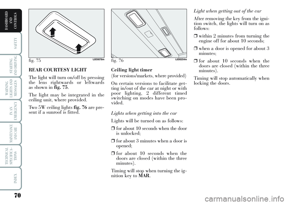
The light will turn on/off by pressing
the lens rightwards or leftwards
as shown in fig. 75.
The light may be integrated in the
ceiling unit, where provided.
Two 5W ceiling lights fig. 76are pre-
sent if a sunroof is fitted.
fig. 75L0D0078mfig. 76L0D0254m
Page 73 of 218
72
SAFETY
STARTING
AND DRIVING
WARNING
LIGHTS AND
MESSAGES
IN AN
EMERGENCY
MAINTENANCE
AND CARE
TECHNICAL
SPECIFICA-
TIONS
INDEX
DASHBOARD
AND
CONTROLS
FUEL CUT OFF
SWITCH
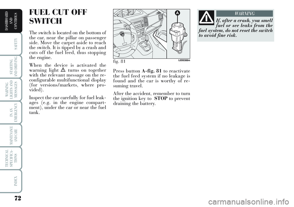
The switch is located on the bottom of
the car, near the pillar on passenger
side. Move the carpet aside to reach
the switch. It is tipped by a crash and
cuts off the fuel feed, thus stopping
the engine.
When the device is activated the
warning light
èturns on together
with the relevant message on the re-
configurable multifunctional display
(for versions/markets, where pro-
vided).
Inspect the car carefully for fuel leak-
ages (e.g. in the engine compart-
ment), under the car or near the fuel
tank.
If, after a crash, you smell
fuel or see leaks from the
fuel system, do not reset the switch
to avoid fine risk.
WARNING
fig. 81L0D0388m
Press button A-fig. 81to reactivate
the fuel feed system if no leakage is
found and the car is worthy of re-
suming travel.
After the accident, remember to turn
the ignition key to STOPto prevent
draining the battery.
Page 76 of 218
75
SAFETY
STARTING
AND DRIVING
WARNING
LIGHTS AND
MESSAGES
IN AN
EMERGENCY
MAINTENANCE
AND CARE
TECHNICAL
SPECIFICA-
TIONS
INDEX
DASHBOARD
AND
CONTROLS
REAR COMPARTMENT
CD HOLDER WITH
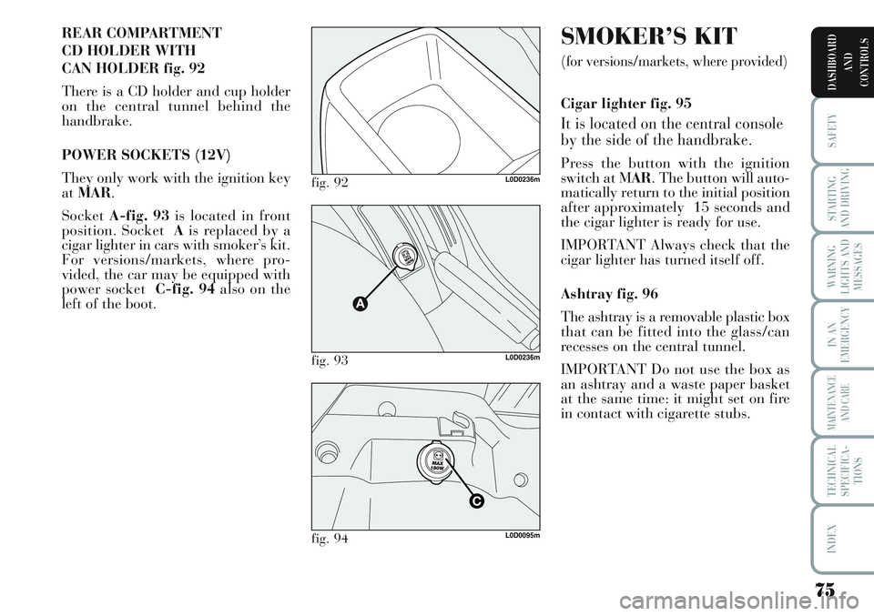
CAN HOLDER fig. 92
There is a CD holder and cup holder
on the central tunnel behind the
handbrake.
POWER SOCKETS (12V)
They only work with the ignition key
atMAR.
SocketA-fig. 93is located in front
position. Socket Ais replaced by a
cigar lighter in cars with smoker’s kit.
For versions/markets, where pro-
vided, the car may be equipped with
power socket C-fig. 94also on the
left of the boot.
fig. 92L0D0236m
fig. 93L0D0236m
fig. 94L0D0095m
SMOKER’S KIT
(for versions/markets, where provided)
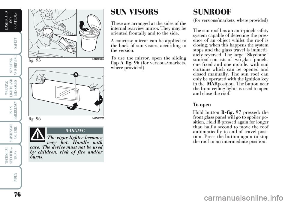
Cigar lighter fig. 95
It is located on the central console
by the side of the handbrake.
Press the button with the ignition
switch at MAR. The button will auto-
matically return to the initial position
after approximately 15 seconds and
the cigar lighter is ready for use.
IMPORTANT Always check that the
cigar lighter has turned itself off.
Ashtray fig. 96
The ashtray is a removable plastic box
that can be fitted into the glass/can
recesses on the central tunnel.
IMPORTANT Do not use the box as
an ashtray and a waste paper basket
at the same time: it might set on fire
in contact with cigarette stubs.
Page 77 of 218
SUN VISORS
These are arranged at the sides of the
internal rearview mirror. They may be
oriented frontally and to the side.
A courtesy mirror can be applied to
the back of sun visors, according to
the version.
To use the mirror, open the sliding
flapA-fig. 96(for versions/markets,
where provided).
SUNROOF
(for versions/markets, where provided)
The sun roof has an anti-pinch safety
system capable of detecting the pres-
ence of an object whilst the roof is
closing; when this happens the system
stops and the glass travel is immedi-
ately reversed. The large “Skydome”
sunroof consists of two glass panels,
one fixed and one mobile, with sun
curtains which can be opened and
closed manually. The sun roof can
only be operated with the ignition key
in the MARposition. The button near
the front ceiling lights is used to open
and close the roof.
To o p e n
Hold button B-fig. 97pressed: the
front glass panel will go to spoiler po-
sition. Hold Bpressed again for longer
than half a second to move the roof
automatically to end of travel posi-
tion. Press the button again to stop
the roof in an intermediate position.
76
SAFETY
STARTING
AND DRIVING
WARNING
LIGHTS AND
MESSAGES
IN AN
EMERGENCY
MAINTENANCE
AND CARE
TECHNICAL
SPECIFICA-
TIONS
INDEX
DASHBOARD
AND
CONTROLS
fig. 95L0D0096m
fig. 96L0D0097m
The cigar lighter becomes
very hot. Handle with
care. The device must not be used
by children: risk of fire and/or
burns.
WARNING
Page 78 of 218
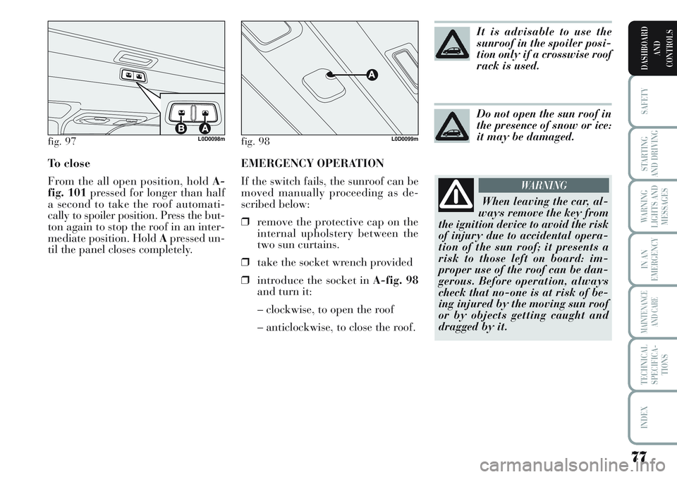
EMERGENCY OPERATION
If the switch fails, the sunroof can be
moved manually proceeding as de-
scribed below:
❒remove the protective cap on the
internal upholstery between the
two sun curtains.
❒take the socket wrench provided
❒introduce the socket in A-fig. 98
and turn it:
– clockwise, to open the roof
– anticlockwise, to close the roof. To close
From the all open position, hold A-
fig. 101pressed for longer than half
a second to take the roof automati-
cally to spoiler position. Press the but-
ton again to stop the roof in an inter-
mediate position. Hold Apressed un-
til the panel closes completely.
77
SAFETY
STARTING
AND DRIVING
WARNING
LIGHTS AND
MESSAGES
IN AN
EMERGENCY
MAINTENANCE
AND CARE
TECHNICAL
SPECIFICA-
TIONS
INDEX
DASHBOARD
AND
CONTROLS
fig. 97L0D0098mfig. 98L0D0099m
It is advisable to use the
sunroof in the spoiler posi-
tion only if a crosswise roof
rack is used.
Do not open the sun roof in
the presence of snow or ice:
it may be damaged.
When leaving the car, al-
ways remove the key from
the ignition device to avoid the risk
of injury due to accidental opera-
tion of the sun roof; it presents a
risk to those left on board: im-
proper use of the roof can be dan-
gerous. Before operation, always
check that no-one is at risk of be-
ing injured by the moving sun roof
or by objects getting caught and
dragged by it.
WARNING