tow Lancia Thema 2013 Owner handbook (in English)
[x] Cancel search | Manufacturer: LANCIA, Model Year: 2013, Model line: Thema, Model: Lancia Thema 2013Pages: 336, PDF Size: 3.87 MB
Page 90 of 336
the far end, a call on hold may not
become active automatically. This is
cell phone-dependent.
Redial
Press the “Redial” soft-key,
or press the
and after the “Lis-
tening” prompt and the following
beep, say “Redial”,
After the “Listening” prompt and the following beep, say “Redial”,
The Uconnect™ Phone will call the last number that was dialed from
your mobile phone.
Call Continuation
Call continuation is the progression of
a phone call on the Uconnect™ Phone
after the vehicle ignition key has been
switched to OFF.
NOTE: The call will remain
within the vehicle audio system
until the phone becomes out of
range for the Bluetooth® connec-
tion. It is recommended to press
the “transfer” soft-key when leav-
ing the vehicle. UCONNECT™ PHONE
FEATURES
Emergency Assistance
If you are in an emergency and the
mobile phone is reachable:
Pick up the phone and manually
dial the emergency number for
your area.
If the phone is not reachable and the
Uconnect™ Phone is operational, you
may reach the emergency number as
follows:
Press the
button to begin.
After the “Listening” prompt and the following beep, say “Call Emer-
gency or Dial Emergency” and the
Uconnect™ Phone will instruct the
paired mobile phone to call the
emergency number. This feature is
supported in the U.S., Canada, and
Mexico.
NOTE:
The Emergency call may also be initiated by using the touch-
screen. The emergency number dialed is
based on the country where the
vehicle is purchased. The num-
ber dialed may not be appli-
cable with the available mobile
service and area.
The Uconnect™ Phone does slightly lower your chances of
successfully making a phone
call as to that for the mobile
phone directly.
WARNING!
Your phone must be turned on and
connected to the Uconnect™ Phone
to allow use of this vehicle feature
in emergency situations, when the
mobile phone has network coverage
and stays connected to the
Uconnect™ Phone.
Towing Assistance
If you need towing assistance:
Press the
button to begin.
After the “Listening” prompt and the following beep, say “Towing
Assistance”.
84
Page 91 of 336
NOTE:
The towing assistance call mayalso be initiated by touch.
Also, refer to your Warranty Booklet for the correct towing
assistance number for your area.
Voice Mail Calling
To learn how to access your voice
mail, refer to “Working with Auto-
mated Systems”.
Working With Automated Systems
This method is used in instances
where one generally has to press num-
bers on the mobile phone keypad
while navigating through an auto-
mated telephone system.
You can use your Uconnect™ Phone
to access a voice mail system or an
automated service, such as a paging
service or automated customer service
line. Some services require immediate
response selection. In some instances,
that may be too quick for use of the
Uconnect™ Phone. When calling a number with your
Uconnect™ Phone that normally re-
quires you to enter in a touch-tone
sequence on your mobile phone key-
pad, you can utilize the touch-screen
or press the
button and say the
word “Send” then the sequence you
wish to enter. For example, if required
to enter your PIN followed with a
pound, (3 7 4 6 #), you can press the
button and say, “Send 3 7 4 6 #”.
Saying “Send” followed by a number,
or sequence of numbers, is also to be
used for navigating through an auto-
mated customer service center menu
structure, and to leave a number on a
pager.
You can also send stored mobile
phonebook entries as tones for fast
and easy access to voice mail and
pager entries. For example, if you pre-
viously created a Phonebook entry
with First and/or Last Name as
“Voicemail Password”, then if you
press the
button and say “Send
Voicemail Password” the Uconnect™ Phone will then send the correspond-
ing phone number associated with the
phonebook entry, as tones over the
phone.
NOTE:
The first number encountered
for that contact will be sent. All
other numbers entered for that
contact will be ignored.
You may not hear all of the tones due to mobile phone network
configurations. This is normal.
Some paging and voice mail sys- tems have system time out set-
tings that are too short and may
not allow the use of this feature.
Pauses, wait or other characters that are supported by some
phones are not supported over
Bluetooth®. These additional
symbols will be ignored in the
dialing a numbered sequence.
85
Page 116 of 336
HEADLIGHT TIME DELAYThis feature provides the safety of
headlight illumination for up to 90 sec-
onds (programmable) when leaving
your vehicle in an unlit area.To activate the delay feature, place
the ignition in the OFF position while
the headlights are still on. Then, turn
off the headlights within 45 seconds.
The delay interval begins when the
headlight switch is turned off.If you turn the headlights or parking
lights on, or place the ignition in ACC
or RUN, the system will cancel the
delay.If you turn the headlights off before
the ignition, they will turn off in the
normal manner.
NOTE:
The lights must be turned offwithin 45 seconds of placing the
ignition in the OFF position to
activate this feature.
The headlight delay time is pro-
grammable using the Uconnect
Touch™ System, refer to
“Uconnect Touch™ Settings” in
“Understanding Your Instrument
Panel” for further information.SMARTBEAM™
(for versions/markets,
where provided)
The SmartBeam™ system provides
increased forward lighting at night by
automating high beam control
through the use of a digital camera
mounted on the inside rearview mir-
ror. This camera detects vehicle spe-
cific light and automatically switches
from high beams to low beams until
the approaching vehicle is out of view.
NOTE:
SmartBeam™ can be turned on or
off using the Uconnect Touch™
System, refer to “Uconnect
Touch™ Settings” in “Under-
standing Your Instrument Panel”
for further information.
Broken, muddy, or obstructed
headlights and taillights of ve-
hicles in the field of view will
cause the high beams to remain
on longer and not automatically
switch to low beams until you
are closer to the approaching ve-
hicle. Also, dirt, film, and other
obstructions on the windshield
or camera lens will cause the
system to function improperly.
If the windshield or SmartBeam™
mirror is replaced, the SmartBeam™
mirror must be re-aimed to ensure
proper performance. See your local
authorized dealer.
To Activate
1. Turn the headlight switch to the
AUTO headlight position.
2. Push the multifunction lever away
from you (toward front of vehicle) to
engage the high beam mode.
NOTE: This system will not acti-
vate until the vehicle is at or above
32 km/h.
110
Page 117 of 336

To Deactivate
1.
Pull the multifunction lever toward
you (or rearward in car) to manually
deactivate the system (normal opera-
tion of low beams).
2. Push back on the multifunction
lever once again to reactivate the sys-
tem.
DAYTIME RUNNING
LIGHTS (for versions/
markets, where provided)
DRLs come ON when the vehicle is
running and shifted out of park, the
headlights are OFF and the parking
brake is OFF. The headlight switch
must be used for normal nighttime
driving. If a turn signal is activated,
the DRL lamp on the same side of the
vehicle will turn off for the duration of
the turn signal activation. Once the
turn signal is no longer active, the
DRL lamp will illuminate.
NOTE: Depending on your area's
regulations, DRLs may be able to
be turned on and off. The DRLs
can be turned on and off using the Uconnect Touch™ System, refer to
“Uconnect Touch™ Settings” in
“Understanding Your Instrument
Panel” for further information.
ADAPTIVE BI-XENON
HIGH INTENSITY
DISCHARGE HEADLIGHTS
This system automatically swivels the
headlight beam pattern horizontally
to provide increased illumination in
the direction the vehicle is steering.
NOTE:
Each time the Adaptive Headlight
System is turned on, the head-
lights will initialize by perform-
ing a brief sequence of rotations. The Adaptive Headlight System
is active only when the vehicle is
moving forward.
The Adaptive Headlight System
can be turned On or Off using the
Uconnect Touch™ System, refer to
“Uconnect Touch™ Settings” in
“Understanding Your Instrument
Panel” for further information. LIGHTS-ON REMINDER
If the headlights or parking lights are
on after the ignition is placed in the
OFF position, a chime will sound to
alert the driver when the driver's door
is opened.
FOG LIGHTS
The fog light switch is built
into the headlight switch. To
activate the fog lights, turn
the headlamp switch to the
park lamp or headlamp position. Press
the headlight switch once for front fog
lights, press the switch a second time
for front and rear fog lights. Pressing
the switch a third time will deactivate
the rear fog lights, and a fourth time
will deactivate the front fog lights.
Turning the headlight switch off will
also deactivate the fog lights.
An indicator light in the instrument
cluster illuminates when the fog lights
are turned on.
NOTE: The front fog lights will
activate automatically when turn-
ing on the position lights or the low
111
Page 118 of 336

beam headlights if previously de-
activated by turning the headlight
switch off. The rear fog lights will
only turn on by operating the
switch as previously described.
MULTIFUNCTION LEVERThe multifunction lever controls the
operation of the turn signals, headlight
beam selection and passing lights. The
multifunction lever is located on the
left side of the steering column.TURN SIGNALS
Move the multifunction lever up or
down and the arrows on each side of
the instrument cluster flash to show
proper operation of the front and rear
turn signal lights.NOTE:
If either light remains on and
does not flash, or there is a very
fast flash rate, check for a defec-
tive outside light bulb. If an indi-
cator fails to light when the lever
is moved, it would suggest that
the indicator bulb is defective.A “Turn Signal On” message will
appear in the EVIC (for versions/
markets, where provided) and a
continuous chime will sound if the
vehicle is driven more than 1.6 km
with either turn signal on.LANE CHANGE ASSISTTap the lever up or down once, without
moving beyond the detent, and the
turn signal (right or left) will flash
three times then automatically turn off.HIGH/LOW BEAM SWITCH
Push the multifunction lever away
from you to switch the headlights to
high beam. Pull the multifunction le-
ver toward you to switch the head-
lights back to low beam.
FLASH-TO-PASS
You can signal another vehicle with
your headlights by lightly pulling the
multifunction lever toward you. This
will turn on the high beams headlights
until the lever is released.
COURTESY LIGHTS
The courtesy lights can be turned on
by pressing the top corner of the lens.
To turn the lights off, press the lens a
second time.
FRONT MAP/READING
LIGHTS
The front map/reading lights are
mounted in the overhead console.
Multifunction Lever
Courtesy Lights
112
Page 121 of 336

CAUTION!(Continued)
Always remove any buildup of snow that prevents the wind-
shield wiper blades from return-
ing to the off position. If the wind-
shield wiper control is turned off
and the blades cannot return to
the off position, damage to the
wiper motor may occur.
INTERMITTENT WIPER
SYSTEM
Use the intermittent wiper when
weather conditions make a single
wiping cycle with a variable pause
between cycles desirable. Rotate the
end of the multifunction lever to the
first detent position, and then turn the
end of the lever to select the desired
delay interval. There are four delay
settings, which allow you to regulate
the wipe interval from a minimum of
one cycle every second to a maximum
of approximately 18 seconds between
cycles. The delay intervals will double
in duration when the vehicle speed is
16 km/h or less. MIST FEATURE
Rotate the end of the lever downward
to the Mist position to activate a single
wipe cycle to clear off road mist or
spray from a passing vehicle. The
wipers will continue to operate until
you release the multifunction lever.
NOTE: The mist feature does not
activate the washer pump; there-
fore, no washer fluid will be
sprayed on the windshield. The
wash function must be used in
order to spray the windshield with
washer fluid.
WINDSHIELD WASHERS
To use the washer, push the multi-
function lever inward (toward the
steering column) and hold it for as
long as washer spray is desired.
If you activate the washer while the
windshield wiper control is in the
delay range, the wipers will operate
for two wipe cycles after releasing the
lever and then resume the intermit-
tent interval previously selected.
If you activate the washer while the
windshield wiper is turned off, the
wipers will operate for three wipe
cycles and then turn off.
WARNING!Sudden loss of visibility through the
windshield could lead to a collision.
You might not see other vehicles or
other obstacles. To avoid sudden ic-
ing of the windshield during freez-
ing weather, warm the windshield
with the defroster before and during
windshield washer use.RAIN SENSING WIPERS
(for versions/markets,
where provided)
This feature senses moisture on the
windshield and automatically acti-
vates the wipers for the driver. The
feature is especially useful for road
splash or over spray from the wind-
shield washers of the vehicle ahead.
Rotate the end of the multifunction
lever to one of four settings to activate
this feature.
115
Page 123 of 336
TILT/TELESCOPING
STEERING COLUMN
This feature allows you to tilt the
steering column upward or down-
ward. It also allows you to lengthen or
shorten the steering column. The tilt/
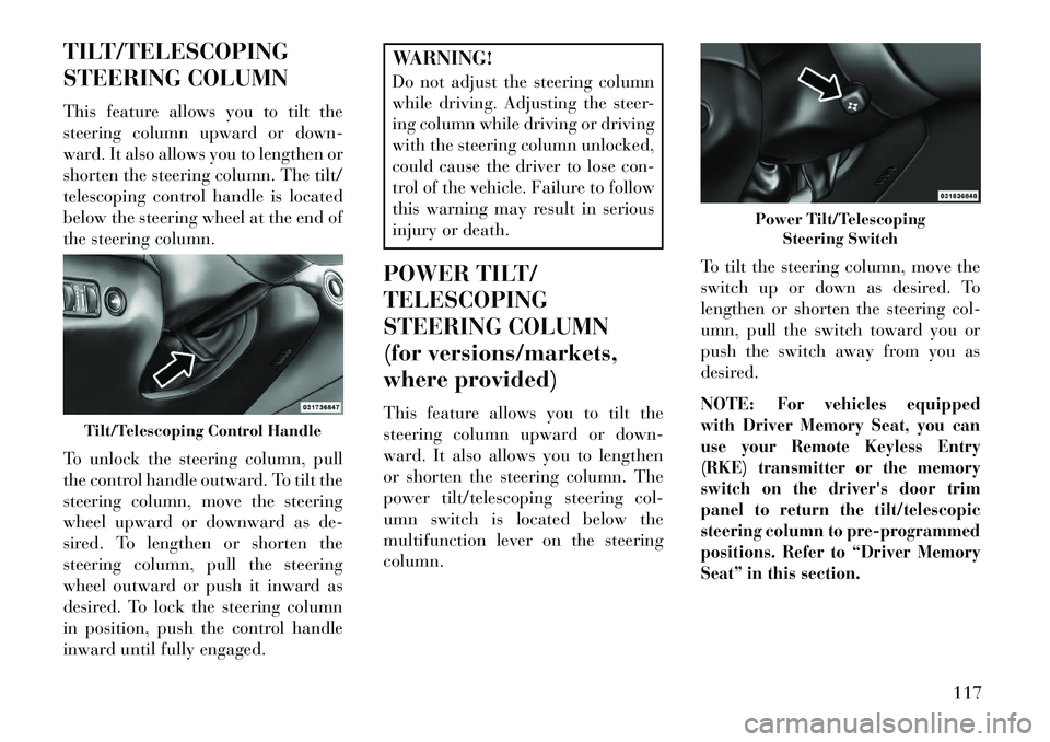
telescoping control handle is located
below the steering wheel at the end of
the steering column.
To unlock the steering column, pull
the control handle outward. To tilt the
steering column, move the steering
wheel upward or downward as de-
sired. To lengthen or shorten the
steering column, pull the steering
wheel outward or push it inward as
desired. To lock the steering column
in position, push the control handle
inward until fully engaged.
WARNING!
Do not adjust the steering column
while driving. Adjusting the steer-
ing column while driving or driving
with the steering column unlocked,
could cause the driver to lose con-
trol of the vehicle. Failure to follow
this warning may result in serious
injury or death.
POWER TILT/
TELESCOPING
STEERING COLUMN
(for versions/markets,
where provided)
This feature allows you to tilt the
steering column upward or down-
ward. It also allows you to lengthen
or shorten the steering column. The
power tilt/telescoping steering col-
umn switch is located below the
multifunction lever on the steering
column. To tilt the steering column, move the
switch up or down as desired. To
lengthen or shorten the steering col-
umn, pull the switch toward you or
push the switch away from you as
desired.
NOTE:
For vehicles equipped
with Driver Memory Seat, you can
use your Remote Keyless Entry
(RKE) transmitter or the memory
switch on the driver's door trim
panel to return the tilt/telescopic
steering column to pre-programmed
positions. Refer to “Driver Memory
Seat” in this section.
Tilt/Telescoping Control Handle
Power Tilt/Telescoping Steering Switch
117
Page 125 of 336
ADJUSTABLE PEDALS
(for versions/markets,
where provided)
The adjustable pedals system is de-
signed to allow a greater range of
driver comfort for steering wheel tilt
and seat position. This feature allows
the brake and accelerator pedals to
move toward or away from the driver
to provide improved position with the
steering wheel.
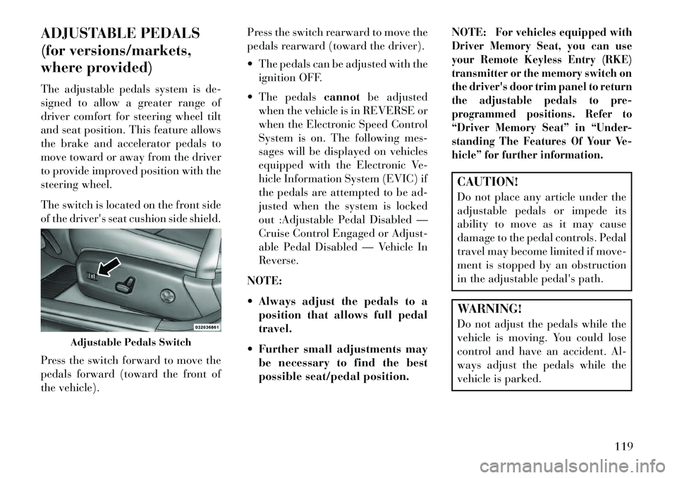
The switch is located on the front side
of the driver's seat cushion side shield.
Press the switch forward to move the
pedals forward (toward the front of
the vehicle).Press the switch rearward to move the
pedals rearward (toward the driver).
The pedals can be adjusted with the
ignition OFF.
The pedals cannotbe adjusted
when the vehicle is in REVERSE or
when the Electronic Speed Control
System is on. The following mes-
sages will be displayed on vehicles
equipped with the Electronic Ve-
hicle Information System (EVIC) if
the pedals are attempted to be ad-
justed when the system is locked
out :Adjustable Pedal Disabled —
Cruise Control Engaged or Adjust-
able Pedal Disabled — Vehicle In
Reverse.
NOTE:
Always adjust the pedals to a position that allows full pedal
travel.
Further small adjustments may be necessary to find the best
possible seat/pedal position. NOTE:
For vehicles equipped with
Driver Memory Seat, you can use
your Remote Keyless Entry (RKE)
transmitter or the memory switch on
the driver's door trim panel to return
the adjustable pedals to pre-
programmed positions. Refer to
“Driver Memory Seat” in “Under-
standing The Features Of Your Ve-
hicle” for further information.
CAUTION!
Do not place any article under the
adjustable pedals or impede its
ability to move as it may cause
damage to the pedal controls. Pedal
travel may become limited if move-
ment is stopped by an obstruction
in the adjustable pedal's path.WARNING!
Do not adjust the pedals while the
vehicle is moving. You could lose
control and have an accident. Al-
ways adjust the pedals while the
vehicle is parked.
Adjustable Pedals Switch
119
Page 128 of 336
If the ACC sensor detects a ve-hicle ahead, ACC will apply
limited braking or acceleration
(not to exceed the original set
speed) automatically to main-
tain a preset following distance,
while matching the speed of the
vehicle ahead.WARNING!
Adaptive Cruise Control (ACC) isa convenience system. It is not a
substitute for active driving in-
volvement. It is always the driv-
er’s responsibility to be attentive
of road, traffic, and weather con-
ditions, vehicle speed, distance to
the vehicle ahead; and, most im-
portantly, brake operation to en-
sure safe operation of the vehicle
under all road conditions. Your
complete attention is always re-
quired while driving to maintain
safe control of your vehicle. Fail-
ure to follow these warnings can
result in a collision and death or
serious personal injury.
(Continued)
WARNING!(Continued)
The ACC system: – Does not react to pedestrians,oncoming vehicles, and sta-
tionary objects (e.g., a stopped
vehicle in a traffic jam or a
disabled vehicle).
–
Cannot take street, traffic, and
weather conditions into account,
and may be limited upon ad-
verse sight distance conditions.– Does not predict the lane cur- vature or the movement of pre-
ceding vehicles and will not
compensate for such changes.
–Does not always fully recognize
complex driving conditions,
which can result in wrong or
missing distance warnings.– Can only apply a maximum of 25% of the vehicle’s braking
capability, and will not bring
the vehicle to a complete stop.
WARNING!You should switch off the ACC sys-
tem: When driving in fog, heavy rain,
heavy snow, sleet, heavy traffic,
and complex driving situations
(e.g., in highway construction
zones).
When entering a turn lane or highway off ramp; when driving
on roads that are winding, icy,
snow-covered, slippery, or have
steep uphill or downhill slopes.
When towing a trailer up or down steep slopes.
When circumstances do not allow safe driving at a constant speed.
Failure to follow these warnings
can result in a collision and death or
serious personal injury.
122
Page 144 of 336
CAUTION!
ParkSense® is only a parking aidand it is unable to recognize every
obstacle, including small ob-
stacles. Parking curbs might be
temporarily detected or not de-
tected at all. Obstacles located
above or below the sensors will
not be detected when they are in
close proximity.
The vehicle must be driven slowly
when using ParkSense® in order
to be able to stop in time when an
obstacle is detected. When back-
ing up, it is recommended that the
driver looks over his/her shoulder
when using ParkSense®.WARNING!
Drivers must be careful when backing up even when using the
ParkSense® Park Assist system.
Always check carefully behind
your vehicle, look behind you,
and be sure to check for pedestri-
ans, animals, other vehicles, ob-
structions, and blind spots before
(Continued)
WARNING!(Continued)
backing up. You are responsible
for safety and must continue to
pay attention to your surround-
ings. Failure to do so can result in
serious injury or death.
Before using the ParkSense® Park Assist system, it is strongly
recommended that the ball
mount and hitch ball assembly is
disconnected from the vehicle
when the vehicle is not used for
towing. Failure to do so can result
in injury or damage to vehicles or
obstacles because the hitch ball
will be much closer to the obstacle
than the rear fascia when the
warning display turns on the
single flashing arc and sounds the
continuous tone. Also, the sensors
could detect the ball mount and
hitch ball assembly, depending on
its size and shape, giving a false
indication that an obstacle is be-
hind the vehicle. PARKVIEW® REAR
BACK UP CAMERA
(for versions/markets,
where provided)
Your vehicle may be equipped with
the ParkView® Rear Back Up Cam-
era that allows you to see an on-screen
image of the rear surroundings of
your vehicle whenever the shift lever
is put into REVERSE. The image will
be displayed on the radio touchscreen
display along with a caution note to
“check entire surroundings” across
the top of the screen. After five sec-
onds this note will disappear. The
ParkView® camera is located on the
rear of the vehicle above the rear
License plate.
When the vehicle is shifted out of
REVERSE, the rear camera mode is
exited and the navigation or audio
screen appears again.
138