turn signal Lancia Thema 2013 Owner handbook (in English)
[x] Cancel search | Manufacturer: LANCIA, Model Year: 2013, Model line: Thema, Model: Lancia Thema 2013Pages: 336, PDF Size: 3.87 MB
Page 74 of 336
OUTSIDE MIRRORS
WITH TURN SIGNAL AND
APPROACH LIGHTING
(for versions/markets,
where provided)
Driver and passenger outside mirrors
with turn signals located within the
mirror housing and approach lighting
located within mirror glass contain
five LEDs.
Three of the LEDs are turn signal
indicators, which flash with the corre-
sponding turn signal lights in the
front and rear of the vehicle. Turning
on the Hazard Warning flashers will
also activate these LEDs.The other two LEDs supply illumi-
nated entry lighting, which turns on in
both mirrors when you use the Remote
Keyless Entry (RKE) transmitter or
open any door. These LEDs shine out-
ward to illuminate the front and rear
door handles. They also shine down-
ward to illuminate the area in front of
the doors.The Illuminated Entry lighting fades
to off after about 30 seconds or it willfade to off immediately once the igni-
tion is placed into the RUN position.
NOTE:
The approach lighting will
not function when the shift lever is
moved out of the PARK position.
TILT MIRRORS IN
REVERSE (for versions/
markets, where provided)Tilt Mirrors in Reverse provides auto-
matic outside mirror positioning which
will aid the driver’s view of the ground
rearward of the front doors. The out-
side mirrors will move slightly down-
ward from the present position when
the vehicle is shifted into REVERSE.
The outside mirrors will then return to
the original position when the vehicle is
shifted out of the REVERSE position.
Each stored memory setting will have
an associated Tilt Mirrors in Reverse
position.NOTE:
The Tilt Mirrors in Reverse fea- ture is not turned on when deliv-
ered from the factory. The Tilt
Mirrors in Reverse feature can
be turned on and off using the
Uconnect Touch™ System. Refer to “Uconnect Touch™ Set-
tings” in “Understanding Your
Instrument Panel” for further
information.
POWER MIRRORS
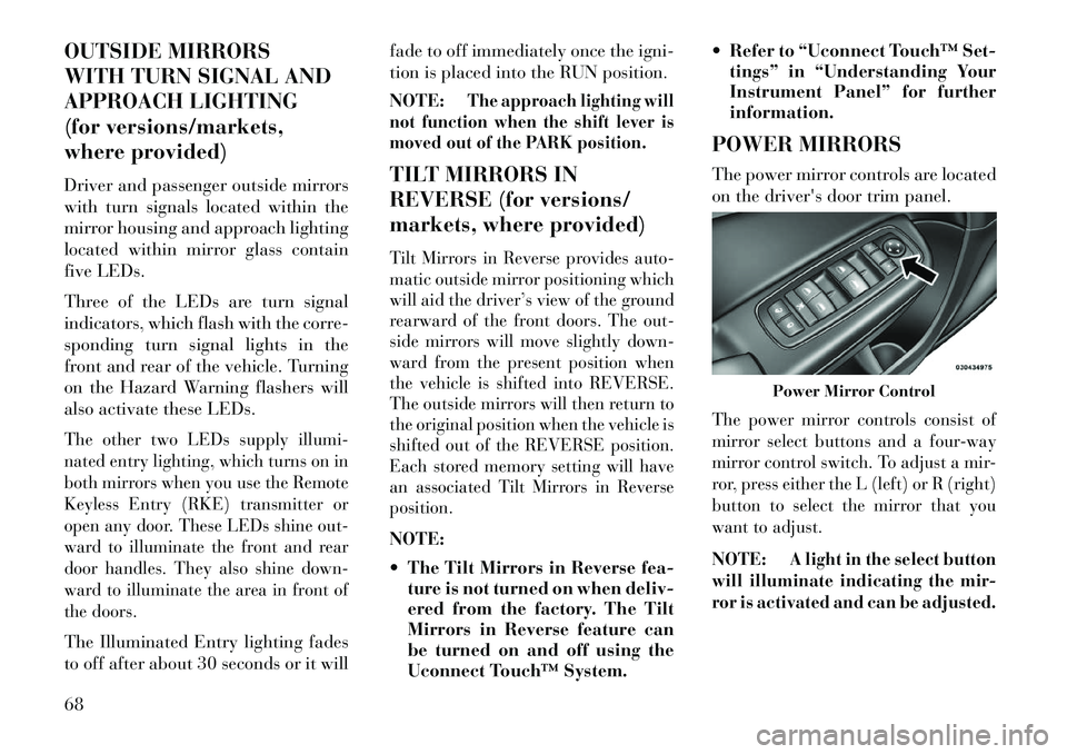
The power mirror controls are located
on the driver's door trim panel.
The power mirror controls consist of
mirror select buttons and a four-way
mirror control switch. To adjust a mir-
ror, press either the L (left) or R (right)
button to select the mirror that you
want to adjust.NOTE:
A light in the select button
will illuminate indicating the mir-
ror is activated and can be adjusted.Power Mirror Control
68
Page 78 of 336
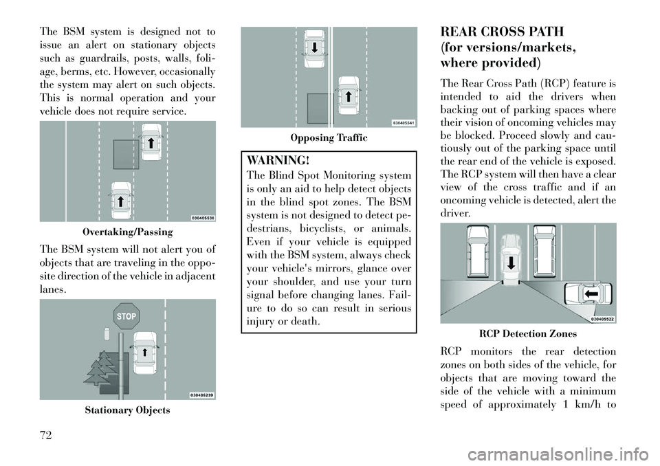
The BSM system is designed not to
issue an alert on stationary objects
such as guardrails, posts, walls, foli-
age, berms, etc. However, occasionally
the system may alert on such objects.
This is normal operation and your
vehicle does not require service.The BSM system will not alert you of
objects that are traveling in the oppo-
site direction of the vehicle in adjacent
lanes.
WARNING!
The Blind Spot Monitoring system
is only an aid to help detect objects
in the blind spot zones. The BSM
system is not designed to detect pe-
destrians, bicyclists, or animals.
Even if your vehicle is equipped
with the BSM system, always check
your vehicle's mirrors, glance over
your shoulder, and use your turn
signal before changing lanes. Fail-
ure to do so can result in serious
injury or death.REAR CROSS PATH
(for versions/markets,
where provided)
The Rear Cross Path (RCP) feature is
intended to aid the drivers when
backing out of parking spaces where
their vision of oncoming vehicles may
be blocked. Proceed slowly and cau-
tiously out of the parking space until
the rear end of the vehicle is exposed.
The RCP system will then have a clear
view of the cross traffic and if an
oncoming vehicle is detected, alert the
driver.
RCP monitors the rear detection
zones on both sides of the vehicle, for
objects that are moving toward the
side of the vehicle with a minimum
speed of approximately 1 km/h to
Overtaking/PassingStationary Objects
Opposing Traffic
RCP Detection Zones
72
Page 79 of 336

3 km/h, to objects moving a maxi-
mum of approximately 16 km/h, such
as in parking lot situations.
NOTE:
In a parking lot situation,
oncoming vehicles can be obscured
by vehicles parked on either side.
If the sensors are blocked by other
structures or vehicles, the system
will not be able to alert the driver.
When RCP is on and the vehicle is in
REVERSE, the driver is alerted using
both the visual and audible alarms,
including reducing the radio volume.WARNING!RCP is not a Back Up Aid system.
It is intended to be used to help a
driver detect an oncoming vehicle in
a parking lot situation. Drivers must
be careful when backing up, even
when using RCP. Always check care-
fully behind your vehicle, look be-
hind you, and be sure to check for
pedestrians, animals, other vehicles,
obstructions, and blind spots before
backing up. Failure to do so can
result in serious injury or death.
MODES OF OPERATION
Three selectable modes of operation
are available in the Uconnect Touch™
System. Refer to “Uconnect Touch™
Settings” in “Understanding Your
Instrument Panel” for further infor-
mation.
Blind Spot Alert
When operating in Blind Spot Alert
mode, the BSM system will provide a
visual alert in the appropriate side
view mirror based on a detected ob-
ject. However, when the system is op-
erating in RCP, the system will re-
spond with both visual and audible
alerts when a detected object is pres-
ent. Whenever an audible alert is re-
quested, the radio volume is reduced.
Blind Spot Alert Lights/Chime
When operating in Blind Spot Alert
Lights/Chime mode, the BSM system
will provide a visual alert in the ap-
propriate side view mirror based on a
detected object. If the turn signal is
then activated, and it corresponds to an alert present on that side of the
vehicle, an audible chime will also be
sounded. Whenever a turn signal and
detected object are present on the
same side at the same time, both the
visual and audio alerts will be issued.
In addition to the audible alert, the
radio (if on) volume will be reduced.
NOTE:
Whenever an audible alert is
requested by the BSM system,
the radio volume is reduced.
If the hazard flashers are on, the system will request the ap-
propriate visual alert only.
When the system is in RCP, the system
shall respond with both visual and
audible alerts when a detected object
is present. Whenever an audible alert
is requested, the radio is also muted.
Turn/hazard signal status is ignored;
the RCP state always requests the
audible chime.
73
Page 80 of 336
Blind Spot Alert OffWhen the BSM system is turned off,
there will be no visual or audible alerts
from either the BSM or RCP systems.NOTE:
The BSM system will store
the current operating mode when
the vehicle is shut off. Each time
the vehicle is started, the previously
stored mode will be recalled and
used.
Astronomy Zone — System
Temporarily Unavailable
The astronomy zone is when the ve-
hicles sensors cannot receive the sig-
nal of another vehicle approaching
due to interference in the reception of
the wavelength signal. When the ve-
hicle enters this zone the blind spot
system will become temporarily un-
available and the EVIC will display
the message “ Blind spot system
unavailable-Astronomy zone”. The
side mirrors LED’s will be lit up and
stay lit until the vehicle exits the zone. UCONNECT™ PHONE
(8.4/8.4N)
UCONNECT TOUCH™
8.4/8.4 NAV
Uconnect™ Phone is a voice-activated,
hands-free, in-vehicle communications
system. Uconnect™ Phone allows you
to dial a phone number with your
mobile phone.
Uconnect™ Phone supports the follow-
ing features:NOTE: Your phone must be
capable of SMS messaging via
Bluetooth® for messaging features
to work properly.
Your mobile phone’s audio is trans-
mitted through your vehicle’s audio
system; the system will automatically
mute your radio when using the
Uconnect™ Phone.
Uconnect™ Phone allows you to
transfer calls between the system and
your mobile phone as you enter or exit
your vehicle and enables you to mute
the system's microphone for private
conversation.
WARNING!
Any voice commanded system
should be used only in safe driving
conditions following all applicable
laws, including laws regarding
phone use. All attention should be
kept on the roadway ahead. Failure
to do so may result in an accident
causing serious injury or death.The Uconnect™ Phone is driven
through your Bluetooth® “Hands-Free
Profile” mobile phone. Uconnect™
features Bluetooth® technology - the
global standard that enables different
electronic devices to connect to each
other without wires or a docking sta-
tion, so Uconnect™ Phone works no
matter where you stow your mobile
phone (be it your purse, pocket, or
briefcase), as long as your phone is
turned on and has been paired to
the vehicle's Uconnect™ Phone. The
Uconnect™ Phone allows up to ten
mobile phones or audio devices to be
linked to the system. Only one linked
(or paired) mobile phone and one
audio device can be used with the
system at a time.
74
Page 117 of 336

To Deactivate
1.
Pull the multifunction lever toward
you (or rearward in car) to manually
deactivate the system (normal opera-
tion of low beams).
2. Push back on the multifunction
lever once again to reactivate the sys-
tem.
DAYTIME RUNNING
LIGHTS (for versions/
markets, where provided)
DRLs come ON when the vehicle is
running and shifted out of park, the
headlights are OFF and the parking
brake is OFF. The headlight switch
must be used for normal nighttime
driving. If a turn signal is activated,
the DRL lamp on the same side of the
vehicle will turn off for the duration of
the turn signal activation. Once the
turn signal is no longer active, the
DRL lamp will illuminate.
NOTE: Depending on your area's
regulations, DRLs may be able to
be turned on and off. The DRLs
can be turned on and off using the Uconnect Touch™ System, refer to
“Uconnect Touch™ Settings” in
“Understanding Your Instrument
Panel” for further information.
ADAPTIVE BI-XENON
HIGH INTENSITY
DISCHARGE HEADLIGHTS
This system automatically swivels the
headlight beam pattern horizontally
to provide increased illumination in
the direction the vehicle is steering.
NOTE:
Each time the Adaptive Headlight
System is turned on, the head-
lights will initialize by perform-
ing a brief sequence of rotations. The Adaptive Headlight System
is active only when the vehicle is
moving forward.
The Adaptive Headlight System
can be turned On or Off using the
Uconnect Touch™ System, refer to
“Uconnect Touch™ Settings” in
“Understanding Your Instrument
Panel” for further information. LIGHTS-ON REMINDER
If the headlights or parking lights are
on after the ignition is placed in the
OFF position, a chime will sound to
alert the driver when the driver's door
is opened.
FOG LIGHTS
The fog light switch is built
into the headlight switch. To
activate the fog lights, turn
the headlamp switch to the
park lamp or headlamp position. Press
the headlight switch once for front fog
lights, press the switch a second time
for front and rear fog lights. Pressing
the switch a third time will deactivate
the rear fog lights, and a fourth time
will deactivate the front fog lights.
Turning the headlight switch off will
also deactivate the fog lights.
An indicator light in the instrument
cluster illuminates when the fog lights
are turned on.
NOTE: The front fog lights will
activate automatically when turn-
ing on the position lights or the low
111
Page 118 of 336

beam headlights if previously de-
activated by turning the headlight
switch off. The rear fog lights will
only turn on by operating the
switch as previously described.
MULTIFUNCTION LEVERThe multifunction lever controls the
operation of the turn signals, headlight
beam selection and passing lights. The
multifunction lever is located on the
left side of the steering column.TURN SIGNALS
Move the multifunction lever up or
down and the arrows on each side of
the instrument cluster flash to show
proper operation of the front and rear
turn signal lights.NOTE:
If either light remains on and
does not flash, or there is a very
fast flash rate, check for a defec-
tive outside light bulb. If an indi-
cator fails to light when the lever
is moved, it would suggest that
the indicator bulb is defective.A “Turn Signal On” message will
appear in the EVIC (for versions/
markets, where provided) and a
continuous chime will sound if the
vehicle is driven more than 1.6 km
with either turn signal on.LANE CHANGE ASSISTTap the lever up or down once, without
moving beyond the detent, and the
turn signal (right or left) will flash
three times then automatically turn off.HIGH/LOW BEAM SWITCH
Push the multifunction lever away
from you to switch the headlights to
high beam. Pull the multifunction le-
ver toward you to switch the head-
lights back to low beam.
FLASH-TO-PASS
You can signal another vehicle with
your headlights by lightly pulling the
multifunction lever toward you. This
will turn on the high beams headlights
until the lever is released.
COURTESY LIGHTS
The courtesy lights can be turned on
by pressing the top corner of the lens.
To turn the lights off, press the lens a
second time.
FRONT MAP/READING
LIGHTS
The front map/reading lights are
mounted in the overhead console.
Multifunction Lever
Courtesy Lights
112
Page 164 of 336
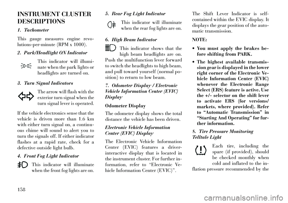
INSTRUMENT CLUSTER
DESCRIPTIONS
1. TachometerThis gauge measures engine revo-
lutions-per-minute (RPM x 1000).2. Park/Headlight ON IndicatorThis indicator will illumi-
nate when the park lights or
headlights are turned on.
3. Turn Signal Indicators
The arrow will flash with the
exterior turn signal when the
turn signal lever is operated.
If the vehicle electronics sense that the
vehicle is driven more than 1.6 km
with either turn signal on, a continu-
ous chime will sound to alert you to
turn the signals off. If either indicator
flashes at a rapid rate, check for a
defective outside light bulb.
4. Front Fog Light Indicator
This indicator will illuminate
when the front fog lights are on.
5. Rear Fog Light Indicator
This indicator will illuminate
when the rear fog lights are on.
6. High Beam Indicator This indicator shows that the
high beam headlights are on.
Push the multifunction lever forward
to switch the headlights to high beam,
and pull toward yourself (normal po-
sition) to return to low beam.
7. Odometer Display / Electronic
Vehicle Information Center (EVIC)
Display
Odometer Display
The odometer display shows the total
distance the vehicle has been driven.
Electronic Vehicle Information
Center (EVIC) Display
The Electronic Vehicle Information
Center (EVIC) features a driver-
interactive display that is located in
the instrument cluster. For further in-
formation, refer to “Electronic Ve-
hicle Information Center (EVIC)”. The Shift Lever Indicator is self-
contained within the EVIC display. It
displays the gear position of the auto-
matic transmission.
NOTE:
You must apply the brakes be-
fore shifting from PARK.
The highest available transmis-
sion gear is displayed in the lower
right corner of the Electronic Ve-
hicle Information Center (EVIC)
whenever the Electronic Range
Select (ERS) feature is active. Use
the +/- selector on the shift lever
to activate ERS (for versions/
markets, where provided). Refer
to “Automatic Transmission” in
“Starting And Operating” for fur-
ther information.8. Tire Pressure Monitoring
Telltale Light
Each tire, including the
spare (if provided), should
be checked monthly when
cold and inflated to the in-
flation pressure recommended by the
158
Page 165 of 336
vehicle manufacturer on the vehicle
placard or tire inflation pressure
label.
As an added safety feature, your ve-
hicle has been equipped with a Tire
Pressure Monitoring System (TPMS)
that illuminates a low tire pressure
telltale when one or more of your tires
is significantly under-inflated. Ac-
cordingly, when the low tire pressure
telltale illuminates, you should stop
and check your tires as soon as pos-
sible, and inflate them to the proper
pressure. Driving on a significantly
under-inflated tire causes the tire to
overheat and can lead to tire failure.
Under-inflation also reduces fuel effi-
ciency and tire tread life, and may
affect the vehicle’s handling and stop-
ping ability.
Please note that the TPMS is not a
substitute for proper tire mainte-
nance, and it is the driver’s responsi-
bility to maintain correct tire pres-
sure, even if under-inflation has not
reached the level to trigger illumina-
tion of the TPMS low tire pressure
telltale.Your vehicle has also been equipped
with a TPMS malfunction indicator to
indicate when the system is not oper-
ating properly. The TPMS malfunc-
tion indicator is combined with the
low tire pressure telltale. When the
system detects a malfunction, the tell-
tale will flash for approximately one
minute and then remain continuously
illuminated. This sequence will con-
tinue upon subsequent vehicle start-
ups as long as the malfunction exists.
When the malfunction indicator is il-
luminated, the system may not be
able to detect or signal low tire pres-
sure as intended. TPMS malfunctions
may occur for a variety of reasons,
including the installation of replace-
ment or alternate tires or wheels on
the vehicle that prevent the TPMS
from functioning properly. Always
check the TPMS malfunction telltale
after replacing one or more tires or
wheels on your vehicle, to ensure that
the replacement or alternate tires and
wheels allow the TPMS to continue to
function properly.
CAUTION!
The TPMS has been optimized for
the original equipment tires and
wheels. TPMS pressures and warn-
ing have been established for the
tire size equipped on your vehicle.
Undesirable system operation or
sensor damage may result when us-
ing replacement equipment that is
not of the same size, type, and/or
style. Aftermarket wheels can cause
sensor damage. Do not use tire seal-
ant from a can or balance beads if
your vehicle is equipped with a
TPMS, as damage to the sensors
may result.
9. Malfunction Indicator
Light (MIL) The Malfunction Indicator
Light (MIL) is part of an on-
board diagnostic system,
called OBD, that monitors engine and
automatic transmission control sys-
tems. The light will illuminate when
the key is in the ON/RUN position,
before engine start. If the bulb does
not come on when turning the key
from OFF to ON/RUN, have the con-
dition checked promptly.
159
Page 170 of 336
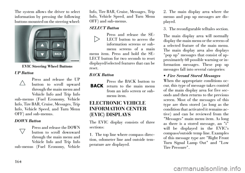
The system allows the driver to select
information by pressing the following
buttons mounted on the steering wheel:UP ButtonPress and release the UP
button to scroll upward
through the main menu and
Vehicle Info and Trip Info
sub-menus (Fuel Economy, Vehicle
Info, Tire BAR, Cruise, Messages, Trip
Info, Vehicle Speed, and Turn Menu
OFF) and sub-menus.
DOWN Button
Press and release the DOWN
button to scroll downward
through the main menu and
Vehicle Info and Trip Info
sub-menus (Fuel Economy, Vehicle Info, Tire BAR, Cruise, Messages, Trip
Info, Vehicle Speed, and Turn Menu
OFF) and sub-menus.
SELECT Button
Press and release the SE-
LECT button to access the
information screens or sub-
menu screens of a main
menu item. Press and hold the SE-
LECT button for two seconds to reset
displayed/selected features that can be
reset.
BACK Button
Press the BACK button to
return to the main menu
from an info screen or sub-
menu item.
ELECTRONIC VEHICLE
INFORMATION CENTER
(EVIC) DISPLAYS
The EVIC display consists of three
sections:
1. The top line where compass direc-
tion, odometer line and outside tem-
perature are displayed. 2.
The main display area where the
menus and pop up messages are dis-
played.
3.
The reconfigurable telltales section.
The main display area will normally
display the main menu or the screens of
a selected feature of the main menu.
The main display area also displays
"pop up" messages that consist of ap-
proximately 60 possible warning or in-
formation messages. These pop up
messages fall into several categories:
Five Second Stored Messages
When the appropriate conditions oc-
cur, this type of message takes control
of the main display area for five sec-
onds and then returns to the previous
screen. Most of the messages of this
type are then stored (as long as the
condition that activated it remains ac-
tive) and can be reviewed from the
"Messages" main menu item. As long
as there is a stored message, an "i"
will be displayed in the EVIC's
compass/outside temp line. Examples
of this message type are "Right Front
Turn Signal Lamp Out" and "Low
Tire Pressure".
EVIC Steering Wheel Buttons
164
Page 171 of 336

Unstored Messages
This message type is displayed indefi-
nitely or until the condition that acti-
vated the message is cleared. Ex-
amples of this message type are "Turn
Signal On" (if a turn signal is left on)
and "Lights On" (if driver leaves the
vehicle).
Unstored Messages Until RUN
This message type is displayed until
the ignition is in the RUN state. An
example of this message type is "Press
Brake Pedal and Push Button to
Start".
Five Second Unstored Messages
When the appropriate conditions oc-
cur, this type of message takes control
of the main display area for five sec-
onds and then returns to the previous
screen. Examples of this message type
are "Memory System Unavailable -
Not in Park" and "Automatic High
Beams On".
The Reconfigurable Telltales section
is divided into the white telltales area
on the right, amber telltales in the
middle, and red telltales on the left.EVIC WHITE TELLTALES
This area will show reconfigurable
white caution telltales. These telltales
include:
Shift Lever Status — Diesel Only
The selected AutoStick gear is dis-
played as D1, D2, D3, D4, D5 and
indicate the Electronic Range Select
(ERS) feature has been engaged and
the gear selected is displayed. For
further information on Autostick,
refer to “Starting And Operating”. Electronic Speed Control ON
This telltale will illuminate
when the electronic speed
control is ON. For further
information, refer to “Elec-
tronic Speed Control” in “Under-
standing The Features Of Your
Vehicle.”
Electronic Speed Control SET
This telltale will illuminate
when the electronic speed
control is SET. For further information, refer to “Electronic
Speed Control” in “Understanding
The Features Of Your Vehicle.”
Adaptive Cruise Control (ACC)
ON (for versions/markets, where
equipped)
This telltale will illuminate
when the ACC is ON. For
further information, refer
to “Adaptive Cruise Control
(ACC)” in “Understanding The Fea-
tures Of Your Vehicle.”
Adaptive Cruise Control (ACC)
SET (for versions/markets, where
equipped)
This telltale will illuminate
when the ACC is SET. For
further information, refer
to “Adaptive Cruise Control
(ACC)” in “Understanding The Fea-
tures Of Your Vehicle.”
165