Lancia Thema 2014 Owner handbook (in English)
Manufacturer: LANCIA, Model Year: 2014, Model line: Thema, Model: Lancia Thema 2014Pages: 332, PDF Size: 3.46 MB
Page 111 of 332
HEATED SEATS (for
versions/markets, where
provided)
On some models, the front and rear
seats may be equipped with heaters in
both the seat cushions and seatbacks.
The front driver and passenger heated
seats are operated using the
Uconnect® System.
WARNING!
Persons who are unable to feelpain to the skin because of ad-
vanced age, chronic illness, dia-
betes, spinal cord injury, medica-
tion, alcohol use, exhaustion or
other physical condition must ex-
ercise care when using the seat
heater. It may cause burns even at
low temperatures, especially if
used for long periods of time.
Do not place anything on the seat or seatback that insulates against
heat, such as a blanket or cush-
ion. This may cause the seat
heater to overheat. Sitting in a
seat that has been overheated
could cause serious burns due to
the increased surface tempera-
ture of the seat.
Front Heated Seat Operations —
Uconnect® 8.4 and 8.4 N:
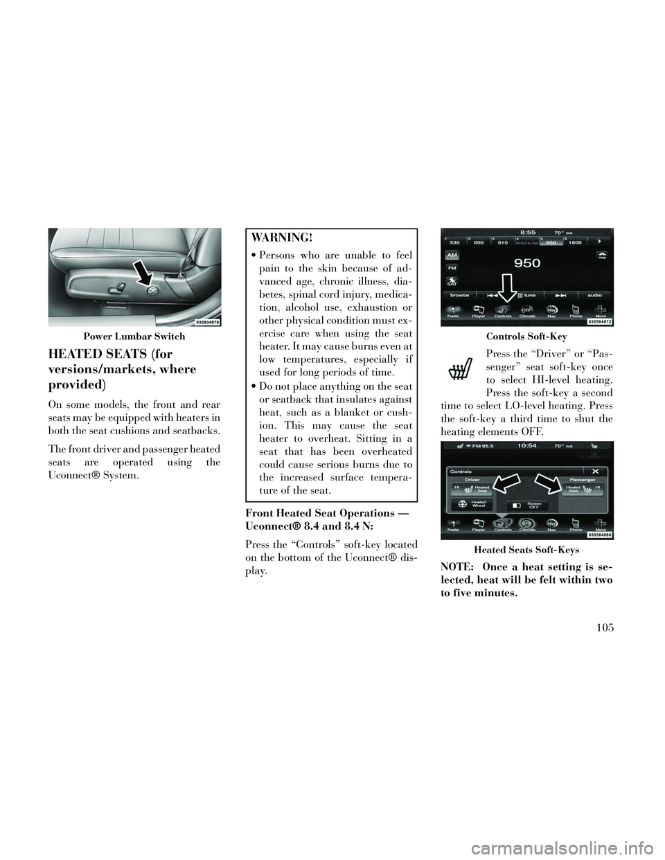
Press the “Controls” soft-key located
on the bottom of the Uconnect® dis-
play. Press the “Driver” or “Pas-
senger” seat soft-key once
to select HI-level heating.
Press the soft-key a second
time to select LO-level heating. Press
the soft-key a third time to shut the
heating elements OFF.
NOTE: Once a heat setting is se-
lected, heat will be felt within two
to five minutes.
Power Lumbar SwitchControls Soft-Key
Heated Seats Soft-Keys
105
Page 112 of 332
When the HI-level setting is selected,
the heater will provide a boosted heat
level during the first four minutes of
operation. Then, the heat output will
drop to the normal HI-level. If the
HI-level setting is selected, the system
will automatically switch to LO-level
after a maximum of 60 minutes of
continuous operation. At that time,
the display will change from HI to LO,
indicating the change. The LO-level
setting will turn OFF automatically
after a maximum of 45 minutes.
Rear Heated Seats
On some models, the two outboard
seats are equipped with heated seats.
The heated seat switches for these
seats are located on the rear of the
center console. There are two heated
seat switches that allow the rear pas-
sengers to operate the seats indepen-
dently.You can choose from HI, LO or OFF
heat settings. Amber indicator lights
in each switch indicate the level of
heat in use. Two indicator lights will
illuminate for HI, one for LO and
none for OFF.
Press the switch once to se-
lect HI-level heating. Press
the switch a second time to
select LO-level heating.
Press the switch a third time to shut
the heating elements OFF.
NOTE:
Once a heat setting is selected, heat will be felt within two to
five minutes.
The engine must be running for the heated seats to operate.
When the HI-level setting is selected,
the heater will provide a boosted heat
level during the first four minutes of
operation. Then, the heat output will
drop to the normal HI-level. If the
HI-level setting is selected, the system
will automatically switch to LO-level
after a maximum of 60 minutes of
continuous operation. At that time, the number of illuminated LEDs
changes from two to one, indicating
the change. The LO-level setting will
turn OFF automatically after a maxi-
mum of 45 minutes.
VENTILATED SEATS (for
versions/markets, where
provided)
On some models, both the driver and
passenger seats are ventilated. Lo-
cated in the seat cushion and seatback
are small fans that draw air from the
seat surface through fine perforations
in the seat cover to help keep the
driver and front passenger cooler in
higher ambient temperatures.
The ventilated seats can be operated
using the Uconnect® System.
NOTE: The engine must be run-
ning for the ventilated seats to op-
erate.
Front Ventilated Seat Operation
— Uconnect® 8.4/8.4N:
Press the “Controls” soft-key located
on the bottom of the Uconnect® dis-
play.
106
Page 113 of 332
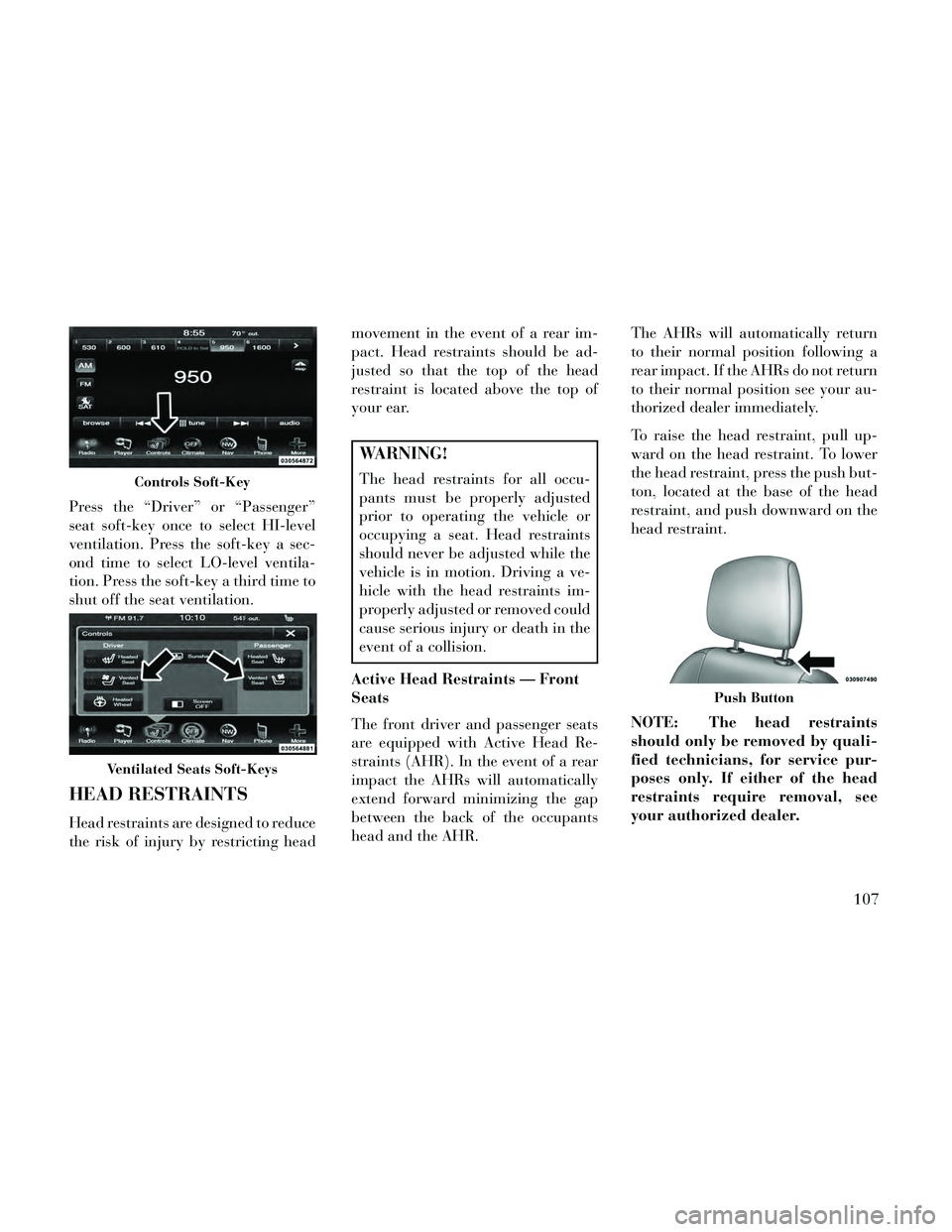
Press the “Driver” or “Passenger”
seat soft-key once to select HI-level
ventilation. Press the soft-key a sec-
ond time to select LO-level ventila-
tion. Press the soft-key a third time to
shut off the seat ventilation.
HEAD RESTRAINTS
Head restraints are designed to reduce
the risk of injury by restricting headmovement in the event of a rear im-
pact. Head restraints should be ad-
justed so that the top of the head
restraint is located above the top of
your ear.
WARNING!
The head restraints for all occu-
pants must be properly adjusted
prior to operating the vehicle or
occupying a seat. Head restraints
should never be adjusted while the
vehicle is in motion. Driving a ve-
hicle with the head restraints im-
properly adjusted or removed could
cause serious injury or death in the
event of a collision.
Active Head Restraints — Front
Seats
The front driver and passenger seats
are equipped with Active Head Re-
straints (AHR). In the event of a rear
impact the AHRs will automatically
extend forward minimizing the gap
between the back of the occupants
head and the AHR. The AHRs will automatically return
to their normal position following a
rear impact. If the AHRs do not return
to their normal position see your au-
thorized dealer immediately.
To raise the head restraint, pull up-
ward on the head restraint. To lower
the head restraint, press the push but-
ton, located at the base of the head
restraint, and push downward on the
head restraint.
NOTE: The head restraints
should only be removed by quali-
fied technicians, for service pur-
poses only. If either of the head
restraints require removal, see
your authorized dealer.Controls Soft-Key
Ventilated Seats Soft-Keys
Push Button
107
Page 114 of 332

WARNING!
Do not place items over the top of
the Active Head Restraint, such as
coats, seat covers or portable DVD
players. These items may interfere
with the operation of the Active
Head Restraint in the event of a
collision and could result in serious
injury or death.
Rear Head Restraints
The center head restraint has two po-
sitions, up or down. When the center
seat is being occupied the head re-
straint should be in the raised posi-
tion. When there are no occupants in
the center seat the head restraint can
be lowered for maximum visibility for
the driver.
To raise the head restraint, pull up-
ward on the head restraint. To lower
the head restraint, press the push but-
ton, located at the base of the head
restraint, and push downward on the
head restraint. NOTE: The outboard head re-
straints are not adjustable. Refer
to “Occupant Restraints” in
“Things To Know Before Starting
Your Vehicle” for tether routing.
FOLDING REAR SEAT
The rear seatbacks can be folded for-
ward to provide an additional storage
area. To fold the rear seatback, pull on
the loops located on the upper seat-
back.
NOTE: These loops can be tucked
away when not in use.
After releasing the seatback, it can be
folded forward.
When the seatback is folded to the
upright position, make sure it is
latched by strongly pulling on the top
of the seatback above the seat strap.
Push ButtonRear Seatback Loop
Folded Rear Seatback
108
Page 115 of 332
WARNING!
Be certain that the seatback issecurely locked into position. If
the seatback is not securely
locked into position, the seat will
not provide the proper stability
for child seats and/or passengers.
An improperly latched seat could
cause serious injury.
The cargo area in the rear of the vehicle (with the rear seatbacks
in the locked-up or folded down
position) should not be used as a
play area by children when the
vehicle is in motion. They could
be seriously injured in a collision.
Children should be seated and us-
ing the proper restraint system.
DRIVER MEMORY SEAT
(for versions/markets,
where provided)
This feature allows the driver to store
up to two different memory profiles
for easy recall through a memory
switch. Each memory profile contains
desired position settings for the driver seat, side mirrors, adjustable pedals
(for versions/markets, where pro-
vided), and power tilt and telescopic
steering column (for versions/
markets, where provided) and a set of
desired radio station presets. Your Re-
mote Keyless Entry (RKE) transmit-
ter can also be programmed to recall
the same positions when the UN-
LOCK button is pressed.
NOTE:
Only one RKE transmitter can
be linked to each of the memory
positions.
Passive Entry door handles can- not be linked to the memory
function. Use either the memory
recall switch or the RKE trans-
mitter (if linked to the memory
feature) to recall memory posi-
tions 1 or 2.
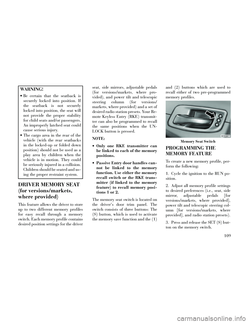
The memory seat switch is located on
the driver's door trim panel. The
switch consists of three buttons: The
(S) button, which is used to activate
the memory save function and the (1) and (2) buttons which are used to
recall either of two pre-programmed
memory profiles.
PROGRAMMING THE
MEMORY FEATURE
To create a new memory profile, per-
form the following:
1. Cycle the ignition to the RUN po-
sition.
2. Adjust all memory profile settings
to desired preferences (i.e., seat, side
mirror, adjustable pedals [for
versions/markets, where provided],
power tilt and telescopic steering col-
umn [for versions/markets, where
provided], and radio station presets).
3. Press and release the SET (S) but-
ton on the memory switch.
Memory Seat Switch
109
Page 116 of 332
4. Within five seconds, press and re-
lease the MEMORY button 1 or 2. The
Electronic Vehicle Information Center
will display which memory position
has been set.
NOTE:
Memory profiles can be set with-out the vehicle in PARK, but the
vehicle must be in PARK to re-
call a memory profile.
The Recall Memory with Remote Key Unlock feature can be
turned on and off using the
Uconnect® System, refer to
“Uconnect® Settings” in “Un-
derstanding Your Instrument
Panel” for further information.
LINKING AND UNLINKING
THE REMOTE KEYLESS
ENTRY TRANSMITTER TO
MEMORY
Your RKE transmitters can be pro-
grammed to recall one of two pre-
programmed memory profiles by
pressing the UNLOCK button on the
RKE transmitter. NOTE: Before programming your
RKE transmitters you must select
the “Memory To FOB” feature
through the Uconnect® system
screen. Refer to “Customer- Pro-
grammable Features —
Uconnect® Access 8.4 Settings ” in
“Understanding Your Instrument
Panel” for further information.
To program your RKE transmitters,
perform the following:
1. Cycle the ignition to the OFF posi-
tion.
2. Select desired memory profile (1)
or (2).
3. Once the profile has been recalled,
press and release the SET (S) button
on the memory switch, then press and
release button (1) or (2) accordingly.
“Memory Profile Set” (1 or 2) will
display in the instrument cluster on
vehicles equipped with the EVIC.
4. Press and release the LOCK but-
ton on the RKE transmitter within 10
seconds.
NOTE: Your RKE transmitters
can be unlinked to your memory
settings by pressing the SET (S)
button followed by the UNLOCK
button on the RKE transmitter in
Step 4 above.
MEMORY POSITION
RECALL
NOTE: The vehicle must be in
PARK to recall memory positions.
If a recall is attempted when the
vehicle is not in PARK, a message
will display in the EVIC.
To recall the memory settings for
driver, press MEMORY button num-
ber (1) on the driver's door or the
UNLOCK button on the RKE trans-
mitter linked to memory position 1.
To recall the memory setting for
driver, press MEMORY button num-
ber (2) on the driver's door or the
UNLOCK button on the RKE trans-
mitter linked to memory position 2.
A recall can be cancelled by pressing
any of the MEMORY buttons (S, 1, or
2) on the driver's door during a recall.
When a recall is cancelled, the driver
110
Page 117 of 332

seat, side mirror, adjustable pedals
(for versions/markets, where pro-
vided), and power tilt and telescopic
steering column (for versions/
markets, where provided) stop mov-
ing. A delay of one second will occur
before another recall can be selected.
EASY ENTRY/EXIT SEAT
(Available With Memory
Seat Only)
This feature provides automatic
driver seat positioning to enhance
driver mobility when entering and ex-
iting the vehicle.
The distance the driver seat moves
depends on where you have the driver
seat positioned when you place the
ignition to the OFF position.
When you cycle the ignition to theOFF position, the driver seat will
move about 60 mm rearward if the
driver seat position is greater than
or equal to 68 mm forward of the
rear stop. The seat will return to its
previously set position when you
place the ignition into the ACC or
RUN position. When you cycle the ignition to the
OFF position, the driver seat will
move to a position 8 mm forward of
the rear stop if the driver seat posi-
tion is between 23 mm and 68 mm
forward of the rear stop. The seat
will return to its previously set po-
sition when you place the ignition
to the ACC or RUN position.
The Easy Entry/Easy Exit feature is disabled when the driver seat po-
sition is less than 23 mm forward of
the rear stop. At this position, there
is no benefit to the driver by moving
the seat for Easy Exit or Easy En-
try.
Each stored memory setting will have
an associated Easy Entry and Easy
Exit position.
NOTE: The Easy Entry/Easy Exit
feature can be enabled or disabled
using the Uconnect® System, refer
to “Uconnect® Settings” in “Un-
derstanding Your Instrument
Panel” for further information.
TO OPEN AND CLOSE
THE HOOD
Two latches must be released to open
the hood.
1. Pull the hood release lever located
under the left side of the instrument
panel.
2. Move to the outside of the vehicle
and push the safety catch to the left.
The safety catch is located under the
center front edge of the hood.
Hood Release Lever
Hood Safety Latch
111
Page 118 of 332
NOTE: Your vehicle may be
equipped with an Active Hood Sys-
tem. Refer to “Occupant Re-
straints” in “Things To Know Be-
fore Starting Your Vehicle” for
further information.
CAUTION!
To prevent possible damage, do not
slam the hood to close it. Lower the
hood until it is open approximately
15 cm, and then drop it. This
should secure both latches. Never
drive your vehicle unless the hood is
fully closed, with both latches en-
gaged.
WARNING!
Be sure the hood is fully latched
before driving your vehicle. If the
hood is not fully latched, it could
open when the vehicle is in motion
and block your vision. Failure to
follow this warning could result in
serious injury or death.
LIGHTS
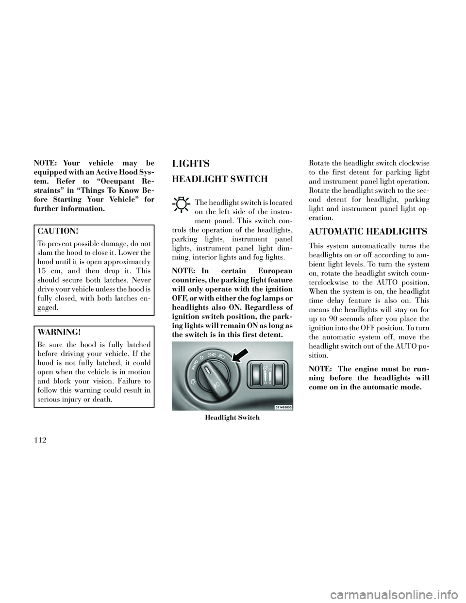
HEADLIGHT SWITCH
The headlight switch is located
on the left side of the instru-
ment panel. This switch con-
trols the operation of the headlights,
parking lights, instrument panel
lights, instrument panel light dim-
ming, interior lights and fog lights.
NOTE: In certain European
countries, the parking light feature
will only operate with the ignition
OFF, or with either the fog lamps or
headlights also ON. Regardless of
ignition switch position, the park-
ing lights will remain ON as long as
the switch is in this first detent. Rotate the headlight switch clockwise
to the first detent for parking light
and instrument panel light operation.
Rotate the headlight switch to the sec-
ond detent for headlight, parking
light and instrument panel light op-
eration.
AUTOMATIC HEADLIGHTS
This system automatically turns the
headlights on or off according to am-
bient light levels. To turn the system
on, rotate the headlight switch coun-
terclockwise to the AUTO position.
When the system is on, the headlight
time delay feature is also on. This
means the headlights will stay on for
up to 90 seconds after you place the
ignition into the OFF position. To turn
the automatic system off, move the
headlight switch out of the AUTO po-
sition.
NOTE: The engine must be run-
ning before the headlights will
come on in the automatic mode.
Headlight Switch
112
Page 119 of 332

HEADLIGHTS ON WITH
WIPERS (Available With
Automatic Headlights Only)
When this feature is active, the head-
lights will turn on approximately 10
seconds after the wipers are turned on
if the headlight switch is placed in the
AUTO position. In addition, the head-
lights will turn off when the wipers are
turned off if they were turned on by
this feature.
NOTE: The Headlights On with
Wipers feature can be turned on or
off using the Uconnect® System,
refer to “Uconnect® Settings” in
“Understanding Your Instrument
Panel” for further information.
HEADLIGHT TIME DELAY
This feature provides the safety of
headlight illumination for up to 90
seconds (programmable) when leav-
ing your vehicle in an unlit area.
To activate the delay feature, place
the ignition in the OFF position while
the headlights are still on. Then, turn
off the headlights within 45 seconds.The delay interval begins when the
headlight switch is turned off.
If you turn the headlights or parking
lights on, or place the ignition in ACC
or RUN, the system will cancel the
delay.
If you turn the headlights off before
the ignition, they will turn off in the
normal manner.
NOTE:
The lights must be turned off
within 45 seconds of placing the
ignition in the OFF position to
activate this feature.
The headlight delay time is pro- grammable using the
Uconnect® System, refer to
“Uconnect® Settings” in “Un-
derstanding Your Instrument
Panel” for further information.
AUTOMATIC HIGH BEAM
(for versions/markets,
where provided)
The Automatic High Beam system
provides increased forward lighting at night by automating high beam con-
trol through the use of a digital cam-
era mounted on the inside rearview
mirror. This camera detects vehicle
specific light and automatically
switches from high beams to low
beams until the approaching vehicle
is out of view.
NOTE:
The Automatic High Beam sys-
tem can be turned on or off using
the Uconnect® System, refer to
“Uconnect® Settings” in “Un-
derstanding Your Instrument
Panel” for further information.
Broken, muddy, or obstructed headlights and taillights of ve-
hicles in the field of view will
cause the high beams to remain
on longer and not automatically
switch to low beams until you
are closer to the approaching ve-
hicle. Also, dirt, film, and other
obstructions on the windshield
or camera lens will cause the
system to function improperly.
113
Page 120 of 332

If the windshield or Automatic High
Beam mirror is replaced, the Auto-
matic High Beam mirror must be re-
aimed to ensure proper performance.
See your local authorized dealer.
To Activate
1. Turn the headlight switch to the
AUTO headlight position.
2. Push the multifunction lever away
from you (toward front of vehicle) to
engage the high beam mode.
NOTE: This system will not acti-
vate until the vehicle is at or above
32 km/h.
To Deactivate
1. Pull the multifunction lever to-
ward you (or rearward in car) to
manually deactivate the system (nor-
mal operation of low beams).
2. Push back on the multifunction
lever once again to reactivate the sys-
tem.DAYTIME RUNNING
LIGHTS (for versions/
markets, where provided)
DRLs come ON when the vehicle is
running and shifted out of park, the
headlights are OFF and the parking
brake is OFF. The headlight switch
must be used for normal nighttime
driving. If a turn signal is activated,
the DRL lamp on the same side of the
vehicle will turn off for the duration of
the turn signal activation. Once the
turn signal is no longer active, the
DRL lamp will illuminate.
NOTE: Depending on your area's
regulations, DRLs may be able to
be turned on and off. The DRLs
can be turned on and off using the
Uconnect® System, refer to
“Uconnect® Settings” in “Under-
standing Your Instrument Panel”
for further information.
ADAPTIVE BI-XENON
HIGH INTENSITY
DISCHARGE HEADLIGHTS
This system automatically swivels the
headlight beam pattern horizontallyto provide increased illumination in
the direction the vehicle is steering.
NOTE:
Each time the Adaptive Head-
light System is turned on, the
headlights will initialize by per-
forming a brief sequence of rota-
tions.
The Adaptive Headlight System is active only when the vehicle is
moving forward.
The Adaptive Headlight System
can be turned On or Off using the
Uconnect® System, refer to
“Uconnect® Settings” in “Under-
standing Your Instrument Panel”
for further information.
LIGHTS-ON REMINDER
If the headlights or parking lights are
on after the ignition is placed in the
OFF position, a chime will sound to
alert the driver when the driver's door
is opened.
114