ECU Lancia Thesis 2006 Owner handbook (in English)
[x] Cancel search | Manufacturer: LANCIA, Model Year: 2006, Model line: Thesis, Model: Lancia Thesis 2006Pages: 386, PDF Size: 8.69 MB
Page 83 of 386

82
The results of research on the best
child restraint systems are contained
in the European Standard ECE-
R44. This Standard enforces the use
of restraint systems classified in five
groups:
Group 0 - weight 0-10 kg
Group 0+ - weight 0-13 kg
Group 1 weight 9-18 kg
Group 2 weight 15-25 kg
Group 3 weight 22-36 kg
The groups partially overlap. This
is because there are systems which
cover more than one weight group
(fig. 76).All restraint systems must show
homologation data and control
markings on a tag which is solidly
fastened to the system and cannot be
removed.
Children weighing more than 1.5
m are, with reference to restrain sys-
tems, considered adults and can
wear normal seat belts.
We recommend using Lineaccessori
Lancia child restraint systems for
each weight group. These systems
were specifically designed and tested
for Lancia cars.GROUP 0 and 0+
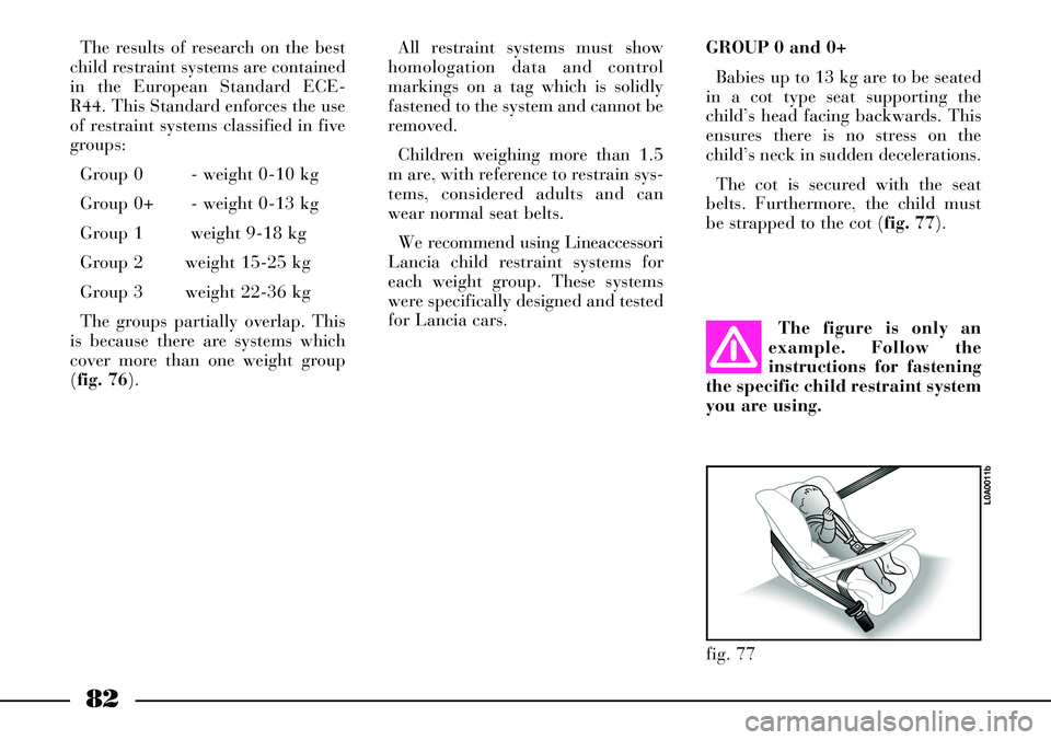
Babies up to 13 kg are to be seated
in a cot type seat supporting the
child’s head facing backwards. This
ensures there is no stress on the
child’s neck in sudden decelerations.
The cot is secured with the seat
belts. Furthermore, the child must
be strapped to the cot (fig. 77).
The figure is only an
example. Follow the
instructions for fastening
the specific child restraint system
you are using.
fig. 77
L0A0011b
Page 84 of 386

83
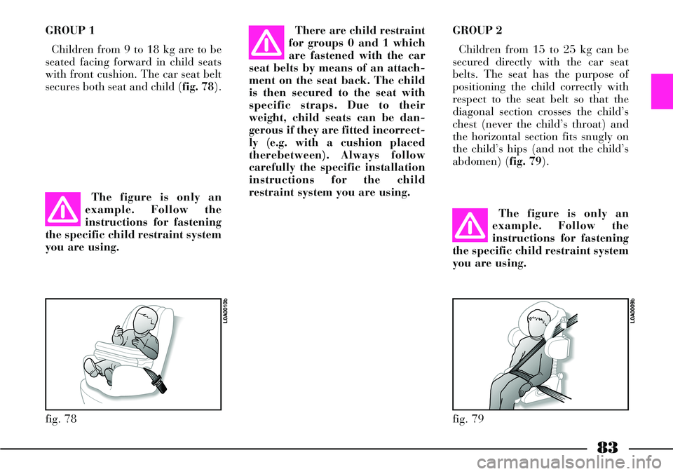
GROUP 1
Children from 9 to 18 kg are to be
seated facing forward in child seats
with front cushion. The car seat belt
secures both seat and child (fig. 78).There are child restraint
for groups 0 and 1 which
are fastened with the car
seat belts by means of an attach-
ment on the seat back. The child
is then secured to the seat with
specific straps. Due to their
weight, child seats can be dan-
gerous if they are fitted incorrect-
ly (e.g. with a cushion placed
therebetween). Always follow
carefully the specific installation
instructions for the child
restraint system you are using.GROUP 2
Children from 15 to 25 kg can be
secured directly with the car seat
belts. The seat has the purpose of
positioning the child correctly with
respect to the seat belt so that the
diagonal section crosses the child’s
chest (never the child’s throat) and
the horizontal section fits snugly on
the child’s hips (and not the child’s
abdomen) (fig. 79).
The figure is only an
example. Follow the
instructions for fastening
the specific child restraint system
you are using.The figure is only an
example. Follow the
instructions for fastening
the specific child restraint system
you are using.
fig. 78
L0A0010b
fig. 79
L0A0009b
Page 88 of 386

87
fig. 84
L0A0420b
fig. 85
L0A0255b
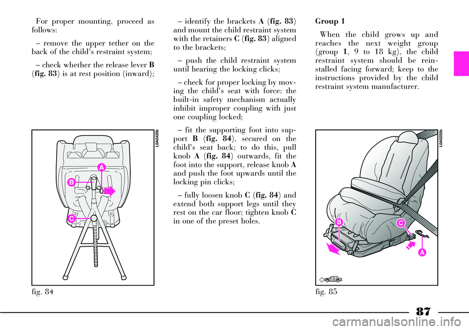
For proper mounting, proceed as
follows:
– remove the upper tether on the
back of the child's restraint system;
– check whether the release lever B
(fig. 83) is at rest position (inward);– identify the brackets A(fig. 83)
and mount the child restraint system
with the retainers C(fig. 83) aligned
to the brackets;
– push the child restraint system
until hearing the locking clicks;
– check for proper locking by mov-
ing the child's seat with force: the
built-in safety mechanism actually
inhibit improper coupling with just
one coupling locked;
– fit the supporting foot into sup-
port B(fig. 84), secured on the
child's seat back; to do this, pull
knob A(fig. 84) outwards, fit the
foot into the support, release knob A
and push the foot upwards until the
locking pin clicks;
– fully loosen knob C(fig. 84) and
extend both support legs until they
rest on the car floor; tighten knob C
in one of the preset holes.Group 1
When the child grows up and
reaches the next weight group
(group 1, 9 to 18 kg), the child
restraint system should be rein-
stalled facing forward; keep to the
instructions provided by the child
restraint system manufacturer.
Page 89 of 386

88
FRONT AND SIDE
AIRBAGS
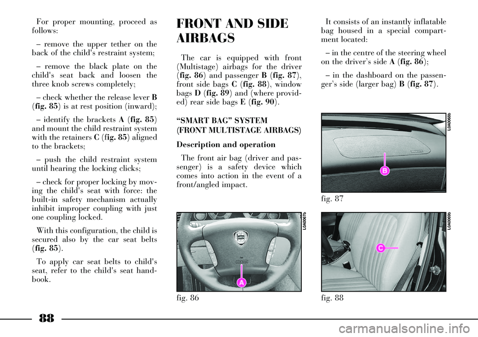
The car is equipped with front
(Multistage) airbags for the driver
(fig. 86) and passenger B(fig. 87),
front side bags C (fig. 88), window
bags D(fig. 89) and (where provid-
ed) rear side bags E(fig. 90).
“SMART BAG” SYSTEM
(FRONT MULTISTAGE AIRBAGS)
Description and operation
The front air bag (driver and pas-
senger) is a safety device which
comes into action in the event of a
front/angled impact.
fig. 86
L0A0067b
For proper mounting, proceed as
follows:
– remove the upper tether on the
back of the child's restraint system;
– remove the black plate on the
child's seat back and loosen the
three knob screws completely;
– check whether the release lever B
(fig. 85) is at rest position (inward);
– identify the brackets A(fig. 85)
and mount the child restraint system
with the retainers C(fig. 85) aligned
to the brackets;
– push the child restraint system
until hearing the locking clicks;
– check for proper locking by mov-
ing the child's seat with force: the
built-in safety mechanism actually
inhibit improper coupling with just
one coupling locked.
With this configuration, the child is
secured also by the car seat belts
(fig. 85).
To apply car seat belts to child's
seat, refer to the child's seat hand-
book.It consists of an instantly inflatable
bag housed in a special compart-
ment located:
– in the centre of the steering wheel
on the driver’s side A (fig. 86);
– in the dashboard on the passen-
ger’s side (larger bag) B(fig. 87).
fig. 87
L0A0068b
fig. 88
L0A0069b
Page 158 of 386

The climate control system can be
deactivated also by the rear control
panel, when operating: press repeat-
edly or keep pressed button 7 (fig.
122) until all the fan bars on the dis-
play turn off and message OFFis
displayed.
To exclude the rear control panel,
press again button REAR; the but-
ton led turns off and the front-seat
passenger’s controls are operating
again.
Air recirculation on/off button
(3 fig. 121)
The air recirculation function is
controlled according to three strate-
gies:
– automatic operation (button left
led on);
– forced ventilation on (recircula-
tion always on), the right led on the
button will come on;– forced deactivation off (recircula-
tion always off, air taken from the
outside), both leds on the button will
go off.
The three conditions are obtained
by pressing the air recirculation but-
ton 3in sequence.
When the air recirculation function
is automatically controlled by the
system, the left led on the air recir-
culation button is turned on, while
the right led is on or off according to
the actual recirculation conditions
(on or off).
During automatic operation, the
recirculation function is automati-
cally switched on when the pollution
sensor detects the presence of pollut-
ed air, e.g. in cities, queues, tunnels
and during windscreen wiper opera-
tion (due to the characteristic smell
of alcohol). In addition, if the compressor is on
and the outside temperature is over
5 °C, to prevent air polluted by
exhaust gases getting inside the pas-
senger compartment during stops,
the system stops air recirculation
when the car speed is lower than 6
km/h. When the car speed returns
over 12 km/h, the system restores
the previous conditions.
After using the air recirculation
function for a long time (over 15
consecutive minutes), the system
automatically stops it for safety rea-
sons, thus letting air be changed.
When air recirculation manual
control is set (button left led off),
message FULLon the display is off.
157
Page 168 of 386

167
This control is accepted by CON-
NECT only if:
– outside temperature lower than 20
°C
– coolant temperature lower than 50
°C
– the ignition key is at STOPor re-
moved
– car battery charged
– sufficient fuel level
– the timer is deactivated.
Switching the heater on
To switch the heater on, press the
remote control button ONfor 1 or 2
seconds, while keeping the antenna in
vertical position; the positive or un-
successful activation is indicated by
the remote control red led Bin the fol-
lowing way:
– the led turns on for about 2 sec-
onds = the signal has been correctly
received and the heater has been ac-
tivated– the led flashes for about 2 seconds
= the signal has not been received.
In the latter case you are advised to
move before trying to activate it by
pressing again the ONbutton.
After the confirmation activation,
the led Bwill flash every 2 seconds for
the whole operation cycle duration.
IMPORTANTIf led Bturns on with
green colour, press twice both remote
control buttons ONand OFFwithin 1
second to set the red colour.
Activation length
When pressing the remote control
button ONthe last recorded activa-
tion length is always activated.
To see the recorded length, press at
the same time for three consecutive
times within 1 second, the remote
control buttons ONand OFF, count
the number of flashes of led Bthen
compare them to those shown in the
table below, including also the first
flash appearing the third time you
press the buttons. Default activation length is 30 min-
utes but it can be changed through
the following procedure:
– press at the same time for three
consecutive times within 1 second, the
remote control buttons ONand OFF
– count the number of flashes of led
Bincluding also the first flash ap-
pearing the third time you press but-
tons ONand OFF
– press OFFto set the length suc-
cessive to the set one (press OFFfor
several times to set the required
length in sequence)
– wait for about 10 seconds for timer
storing.
Page 233 of 386

232
The mobile net can be secured to
one of the two positions provided in
the front part of the boot (fig. 197-
198), by hooking it onto seats Aand
B(fig. 199).To secure the net, insert hooks A
(fig. 200) in seats Bthen push
downwards.
The net can be unhooked by slip-
ping it off upwards, by pressing
down button Con the attachment.ANCHORING THE LOAD
The loads can be secured with belts
(not provided), attached to the spe-
cific rings (fig. 201-202) in the boot
corners.
fig. 197
L0A0046b
fig. 198
L0A0047b
fig. 199
L0A0099b
fig. 200
L0A0048b
fig. 201
L0A0219b
Page 234 of 386

233
These rings can also be used to fas-
ten the luggage net (optional, can be
purchased at a Lancia Dealership).LUGGAGE TRANSPORT -
IMPORTANT
The car is equipped with a system
that automatically keeps headlight
height steady on different loading
conditions. The adjusting system
works properly with the maximum
allowed loads: always make sure
that the load you are carrying does
not exceed the values specified in
chapter “Technical Specifications”.
When using the boot,
make sure the load you
are carrying does not
exceed the maximum allowed
weight (see the “Technical
Specifications” chapter). Also
ensure the items in the boot are
arranged properly and fastened
with straps to the specific hooks
to prevent them being thrown for-
wards and injuring passengers
should you brake sharply.Heavy loads which are
not securely anchored
could seriously injure
passengers in the event of an
accident.
If you need to carry
petrol in a jerry-can,
always comply with the
law regulations and use a certi-
fied can, which must be properly
secured to the fastening rings. In
any case, the risk of fire in case of
accident is high.
fig. 202
L0A0220b
Page 237 of 386

236
fig. 211
L0A0094b
After placing the load with the pro-
tection, secure it by means of the
belt to prevent it from shifting in
case of sudden braking or collision.
To secure the protection with the
load:
1) Get the protection belt to pass
around the armrest.
2) Hold the belt tight by pulling its
end, while holding buckle A (fig.
209).3) Secure the load by inserting the
attachment of belt A (fig. 210) into
the buckle of the central rear safety
belt.To release the protection with the
load:
1) Release the belt by pressing the
button on the safety belt buckle.
2) Loosen the tension of the belt by
making the latter slide into buckle A
(fig. 211) while pressing button B.
3) Slip the protection belt from the
armrest and fold it up into its seat.
Close the flaps by pushing them
into their seat to locking.
fig. 209
L0A0093b
fig. 210
L0A0095b
Page 242 of 386

241
After travelling a few
kilometres, check that the
screws securing the rack
are tight.
Distribuite the load
evenly and remember,
when driving the car, that
the car is now more susceptible to
side wind.
Never exceed the per-
mitted weights (refer to
the “Technical specifica-
tions” chapter).ROOF RACK –
SKI RACK
ANCHORAGE POINTS
The car roof features four brackets
for anchoring the roof rack/ski rack
(fig. 219); these brackets are hidden
by small covers.
To use the brackets, lift the covers
by levering on point A(fig. 220).
Fasten the roof rack/ski rack to the
brackets, by following the provided
instructions.After removing the roof rack/ski
rack, lower the covers by engaging
them into their seats.
IMPORTANTStrictly comply with
the law regulations in force concern-
ing maximum overall dimensions.
Strictly follow the assembly
instructions provided with the roof
rack/ski rack set. Assembly should
be made by qualified personnel.
fig. 219
L0A0083b
fig. 220
L0A0084b