ESP Lancia Thesis 2006 Owner handbook (in English)
[x] Cancel search | Manufacturer: LANCIA, Model Year: 2006, Model line: Thesis, Model: Lancia Thesis 2006Pages: 386, PDF Size: 8.69 MB
Page 5 of 386
TRAVELLING SAFELY AND IN HARMONY WITH NATURE
Safety and respect for the environment are the guidelines that inspired the THESIS design from the
drawing board onwards.
This concept has meant that the THESIS has been able to face and pass the strictest safety tests.
So much so that, from this point of view, the car is the best in its class and has probably already incor-
porated features that belong to the future.
In addition, ongoing research into new and effective features to help safeguard the environment
makes the THESIS a car to imitate for this reason as well.
All versions are in fact equipped with environmental protection devices that reduce harmful exhaust
fumes in compliance with the limits provided for by current legislation.
Page 6 of 386
SAFEGUARDING THE ENVIRONMENT
Safeguarding the environment has directed the design and manufacturing of the THESIS right from
the start. The result is the use of materials and the perfection of devices that can reduce or sweep-
ingly reduce harmful influences on the environment.
The THESIS is equipped with environment safeguarding devices which curtail harmful exhaust gas
emissions, is ready to travel well ahead of the most stringent international pollution control stan-
dards.
USE OF ENVIRONMENT-FRIENDLY MATERIALS
None of the car’s components contain asbestos. Padding and the climate control system do not con-
tain CFCs (chlorofluorocarbides) - the gases considered responsible for the destruction of the ozone
layer. Other substances that might pollute air and water tables, such as the cadmium in the rust-proof
coating of the bolts, have been completely replaced with substances that do not harm the environ-
ment.
Page 16 of 386
15
THESIS CONNECT infotelematic
system, in its most refined version,
includes: colour TV set, sound sys-
tem with cassette player, CD-
ROM/Audio CD player, CD-chang-
er, GSM cell phone, navigator, trip
computer and voice commands (for
certain functions of cell phone,
audio system and navigator).
The following pages describe the
system controls and main functions.
The car is provided with a special
supplement dealing with CONNECT
infotelematic system to be used as
quick reference guide for using the
system. Read through this supple-
ment carefully and keep it always
within reach (e.g. in the glove com-
partment).
IMPORTANTFor the navigation
system of the CONNECT, only use
only the original CD provided with
the car or, in any case other CDs of
the same brand.If you drive with the vol-
ume too high you put both
your own life and that of
others in jeopardy. You should
adjust the volume so that you can
hear noises from outside the car
(e.g. horns, ambulance/police
sirens, etc.).
CONNECT CONTROLS (fig. 2)
The CONNECT system functions
can be managed by means of 29
buttons and 2 rotating selectors
(knobs). Certain controls have mul-
tiple functions that are dependent on
the system operating conditions
active.
The type of function that can be
actuated by means of the controls
depend, in some cases, on how long
the button is pressed down (long or
short push), as shown in the follow-
ing table. The Lancia navigation
system helps driver while
he drives, by suggesting
vocally or graphically, the opti-
mum routing to reach his preset
destination. Navigation system
suggestions do not excuse driver
from his full responsibilities due
to his driving behaviour and to
his compliance with road and
other traffic regulations. The
responsibility for road safety
always lies with the car driver,
and it falls on him in any case.IMPORTANTThe provided phone
is of the Single-Band type and there-
fore if your network provider is not
operating with the 900 Mhz GSM
standard, coverage troubles may arise
notwithstanding the roaming. Contact
your network provider for further in-
formation.
Page 20 of 386
19
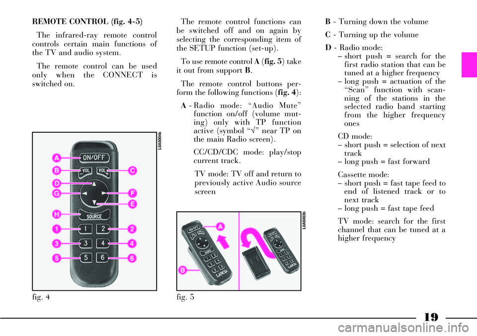
REMOTE CONTROL (fig. 4-5)
The infrared-ray remote control
controls certain main functions of
the TV and audio system.
The remote control can be used
only when the CONNECT is
switched on. The remote control functions can
be switched off and on again by
selecting the corresponding item of
the SETUP function (set-up).
To use remote control A(fig. 5) take
it out from support B.
The remote control buttons per-
form the following functions (fig. 4):
A- Radio mode: “Audio Mute”
function on/off (volume mut-
ing) only with TP function
active (symbol “√” near TP on
the main Radio screen).
CC/CD/CDC mode: play/stop
current track.
TV mode: TV off and return to
previously active Audio source
screenB- Turning down the volume
C- Turning up the volume
D- Radio mode:
– short push = search for the
first radio station that can be
tuned at a higher frequency
– long push = actuation of the
“Scan” function with scan-
ning of the stations in the
selected radio band starting
from the higher frequency
ones
CD mode:
– short push = selection of next
track
– long push = fast forward
Cassette mode:
– short push = fast tape feed to
end of listened track or to
next track
– long push = fast tape feed
TV mode: search for the first
channel that can be tuned at a
higher frequency
fig. 5
L0A5003b
fig. 4
L0A5004b
Page 22 of 386
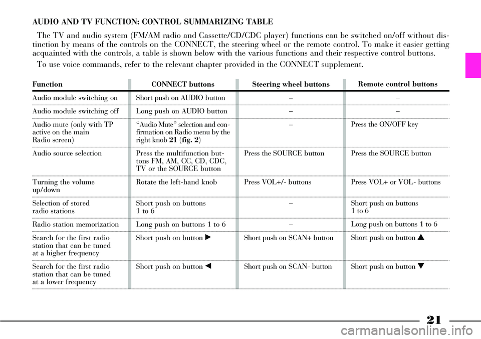
21
Function
Audio module switching on
Audio module switching off
Audio mute (only with TP
active on the main
Radio screen)
Audio source selection
Turning the volumeup/down
Selection of stored
radio stations
Radio station memorization
Search for the first radio
station that can be tuned
at a higher frequency
Search for the first radio
station that can be tuned
at a lower frequencyCONNECT buttons
Short push on AUDIO button
Long push on AUDIO button
“Audio Mute” selection and con-
firmation on Radio menu by the
right knob 21(fig. 2)
Press the multifunction but-
tons FM, AM, CC, CD, CDC,
TV or the SOURCE button
Rotate the left-hand knob
Short push on buttons
1 to 6
Long push on buttons 1 to 6
Short push on button ˙
Short push on button ¯Steering wheel buttons
–
–
–
Press the SOURCEbutton
Press VOL+/- buttons
–
–
Short push on SCAN+ button
Short push on SCAN- buttonRemote control buttons
–
–
Press the ON/OFF key
Press the SOURCEbutton
Press VOL+ or VOL- buttons
Short push on buttons
1 to 6
Long push on buttons 1 to 6
Short push on button N
Short push on button O
AUDIO AND TV FUNCTION: CONTROL SUMMARIZING TABLE
The TV and audio system (FM/AM radio and Cassette/CD/CDC player) functions can be switched on/off without dis-
tinction by means of the controls on the CONNECT, the steering wheel or the remote control. To make it easier getting
acquainted with the controls, a table is shown below with the various functions and their respective control buttons.
To use voice commands, refer to the relevant chapter provided in the CONNECT supplement.
Page 25 of 386
It is absolutely forbidden
to carry out whatever af-
ter-market operation in-
volving steering system or steering
column modifications (e.g.: instal-
lation of anti-theft Device) that
could badly affect performance
and safety, cause the lapse of war-
ranty and also result in non-com-
pliance of the car with homologa-
tion requirements.
24
STEERING COLUMN LOCK
The steering column lock is
engaged automatically after remov-
ing the ignition key.IGNITION
SWITCH
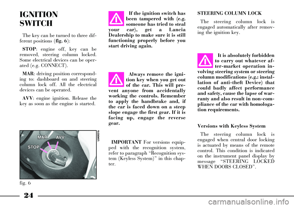
The key can be turned to three dif-
ferent positions (fig. 6):
STOP: engine off, key can be
removed, steering column locked.
Some electrical devices can be oper-
ated (e.g. CONNECT).
MAR: driving position correspond-
ing to: dashboard on and steering
column lock off. All the electrical
devices can be operated.
AVV: engine ignition. Release the
key as soon as the engine is started.If the ignition switch has
been tampered with (e.g.
someone has tried to steal
your car), get a Lancia
Dealership to make sure it is still
functioning properly before you
start driving again.
Always remove the igni-
tion key when you get out
of the car. This will pre-
vent anyone from accidentally
working the controls. Remember
to apply the handbrake and, if
the car is faced down on a steep
slope engage the first gear. If it is
facing up, engage the reverse
gear.
IMPORTANTFor versions equip-
ped with the recognition system,
refer to paragraph “Recognition sys-
tem (Keyless System)” in this chap-
ter.
fig. 6
L0A0021b
Versions with Keyless System
The steering column lock is
engaged when central door locking
is actuated by means of the remote
control. This condition is indicated
on the instrument panel display by
message “STEERING LOCKED
WHEN DOORS CLOSED”.
Page 31 of 386
30
After activating the dead
lock device it will be
impossible to get out of
the passenger compartment: for
this reason this device must be
activated only after making sure
that the passenger compartment
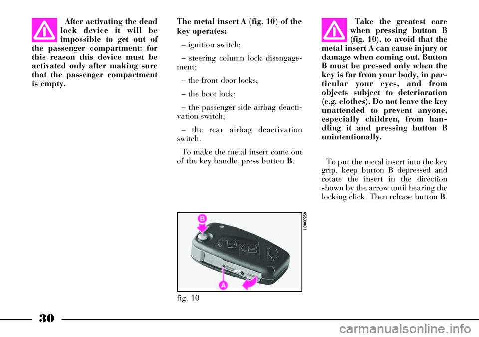
is empty.The metal insert A (fig. 10) of the
key operates:
– ignition switch;
– steering column lock disengage-
ment;
– the front door locks;
– the boot lock;
– the passenger side airbag deacti-
vation switch;
– the rear airbag deactivation
switch.
To make the metal insert come out
of the key handle, press button B.Take the greatest care
when pressing button B
(fig. 10), to avoid that the
metal insert A can cause injury or
damage when coming out. Button
B must be pressed only when the
key is far from your body, in par-
ticular your eyes, and from
objects subject to deterioration
(e.g. clothes). Do not leave the key
unattended to prevent anyone,
especially children, from han-
dling it and pressing button B
unintentionally.
To put the metal insert into the key
grip, keep button Bdepressed and
rotate the insert in the direction
shown by the arrow until hearing the
locking click. Then release button B.
fig. 10
L0A0025b
Page 32 of 386
31
Remote control
The remote control is built into the
key and has three buttons C, Dand E
(fig. 9) and a led F (where required).
The buttons respectively operate the
central opening control, the central
locking control and the boot lock;
the led flashes while the transmitter
is sending the code to the receiver.
This code (rolling code) changes at
each transmission.
To actuate the remote central door
opening, press button C (fig. 9): the
doors will unlock and the indicators
will flash twice. To actuate central
door locking, press button D: the
doors will lock and the indicators
will flash once.By pressing button C, also the
alarm system will be switched off; by
pressing button D, the alarm system
will be switched on and the key led
F(where required) will flash while
the transmitter sends the code to the
receiver: this code (rolling code)
varies at each transmission.
IMPORTANTWhen the remote
control battery is run down, the
dashboard display will show the
symbol Yaccompanied by the mes-
sage “DISCHARGED REMOTE
CONTROLBATTERY”. In this
case, it is advisable to replace the
battery as soon as possible, by fol-
lowing the instructions given below.IMPORTANTThe remote control
operation depends on different fac-
tors, such as possible interference
with electromagnetic waves emitted
by external sources, the battery
charge and the presence of metal
objects near the key and the car. It is
however possible to perform any
procedure using the metal insert of
the key.
Page 44 of 386
43
The functions that can be modified
through the CONNECT system
menu are:
– boot lock release by actuating
central door opening (*);
– central door and tailgate locking
when the car speed exceeds 20
km/h, without actuation of the
deadlock device.
(*) When this function is discon-
nected to lock the boot lock when
the boot is closed, even if the doors
were closed, the remote control or
the key must be used, as it is nor-
mally the case with the doors; thus,
the boot can be opened with the
handle in the event that the key is
left inside the lock.MINISTERIAL HOMOLOGATION
In the respect of the legislation in
force in each country in the matter
of radio-frequency devices, please
note that the homologation number
is printed on the component for
markets where this is required.
IMPORTANTThe code marking
may also be printed on the transmit-
ter and/or the receiver for ver-
sions/markets where this is required.EASY ENTRY/EXIT
SYSTEM
Versions provided with electric
steering wheel adjustment may also
incorporate the Easy Entry/Exit sys-
tem, which allows the driver to get
into and out of the car with
improved ease.
In the cars provided with this sys-
tem, the steering wheel lifts and the
seat goes back before the driver gets
out of the car.
The function is actuated when the
door is opened but only if the igni-
tion key is at STOPor has been
removed.
When the driver opens the door to
get into the car, both the seat and
the steering wheel have already gone
back. The seat and the steering
wheel will return to their normal dri-
ving position after the driver has sat,
closed the door and turned the key
to MAR.
Page 48 of 386
47
For an emergency engine start up
proceed as follows:
– Lay the CID device into the emer-
gency seat A(fig. 21)
– Push on the clutch pedal (manual
gearbox versions) or on the brake
pedal (automatic gearbox versions)
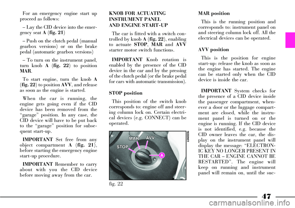
– To turn on the instrument panel,
turn knob A(fig. 22) to position
MAR.
To start engine, turn the knob A
(fig. 22) to positionAVV, and release
as soon as the engine is started.
When the car is running, the
engine gets going even if the CID
device has been removed from the
“garage” position. In any case, the
CID device will have to be put back
to the “garage” position for subse-
quent start-up.
IMPORTANTSet free from any
object compartment A(fig. 21),
before starting the emergency engine
start-up procedure.
IMPORTANTRemember to carry
about with you the CID device
before moving away from the car. KNOB FOR ACTUATING
INSTRUMENT PANEL
AND ENGINE START-UP
The car is fitted with a switch con-
trolled by knob A(fig. 22), enabling
to actuate STOP, MARand AVV
starter motor switch functions.
IMPORTANTKnob rotation is
enabled by the presence of the CID
device in the car and by the pressing
of the clutch pedal (or the brake pedal
for cars with automatic transmission).
STOP position
This position of the switch knob
corresponds to: engine off and steer-
ing column lock on. Certain electri-
cal devices (e.g. CONNECT) can be
operated.MAR position
This is the running position and
corresponds to: instrument panel on
and steering column lock off. All the
electrical devices can be operated.
AVV position
This is the position for engine
start-up: release the knob as soon as
the engine has started. The engine
can be started only when the CID
device is inside the car.
IMPORTANTSystem checks for
the presence of a CID device inside
the passenger compartment, when-
ever a door or the luggage compart-
ment are closed, while the instru-
ment panel is turned on or the
engine is running. If the CID device
is not identified, e.g. because the
CID owner leaves the car, the dis-
play on the instrument panel will
display the message: “ELECTRON-
IC KEY NO LONGER PRESENT IN
THE CAR – ENGINE CANNOT BE
RESTARTED”. The engine will
keep on running and instrument
panel will remain on, until the suc-
fig. 22
L0A0223b