lock Lancia Thesis 2007 Owner handbook (in English)
[x] Cancel search | Manufacturer: LANCIA, Model Year: 2007, Model line: Thesis, Model: Lancia Thesis 2007Pages: 386, PDF Size: 8.69 MB
Page 61 of 386
60
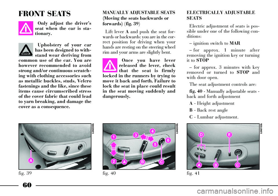
MANUALLY ADJUSTABLE SEATS
(Moving the seats backwards or
forwards) (fig. 39)
Lift lever Aand push the seat for-
wards or backwards: you are in the cor-
rect position for driving when your
hands are resting on the steering wheel
rim and your arms are slightly bent. FRONT SEATS
Only adjust the driver’s
seat when the car is sta-
tionary.
Once you have lever
released the lever, check
that the seat is firmly
locked in the runners by trying to
move it back and forth. Failure to
lock the seat in place could result
in the seat moving suddenly and
dangerously.ELECTRICALLY ADJUSTABLE
SEATS
Electric adjustment of seats is pos-
sible under one of the following con-
ditions:
– ignition switch to MAR
– for approx. 1 minute after
removing the ignition key or turning
it to STOP
– for approx. 3 minutes with key
removed or turned to STOPand
with door open.
The seat adjustment controls are:
fig. 40- Manually adjustable seats -
back and forth adjustment
A- Height adjustment
B- Back rest angle
C- Lumbar adjustment.
fig. 39
L0A0248b
fig. 41
L0A0153b
fig. 40
L0A0249b
Upholstery of your car
has been designed to with-
stand wear deriving from
common use of the car. You are
however recommended to avoid
strong and/or continuous scratch-
ing with clothing accessories such
as metallic buckles, studs, Velcro
fastenings and the like, since these
items cause circumscribed stress
of the cover fabric that could lead
to yarn breaking, and damage the
cover as a consequence.
Page 66 of 386

65
Remember that the head
restraints should be
adjusted to support the
back of your head and not your
neck. Only if they are in this posi-
tion will they be able to provide
effective protection in the event of
a rear-end shunt. Never drive
your car without fitting the head-
rest: this is dangerous and, more-
over, is prohibited by the law.ARMREST (fig. 49)
The armrest Acan be adjusted up
or down to three different positions.
To lift the armrest, pull it from
handgrip B. To lower the armrest,
keep knob Cdepressed.
The armrest incorporates a cli-
mate-controlled bottle/can holder
(refer to the relevant paragraph in
this chapter). To gain access to the
bottle/can holder, lift armrest Aby
pulling it from handgrip B. To close
the bottle/can holder, lower the
armrest until it is locked; to lower it
further, press knob C.HEAD RESTRAINTS (fig. 48)
Where provided, front head
restraints can be adjusted electrical-
ly, so as to adapt to the driver’s
height.
To lift the head restraint, move
control B(fig. 43) to 7; to lower the
head restraint, move the aforesaid
control to 8.
To remove the head restraints,
move them upwards, to refit them,
fit the rods back into the housings
on the seat top.
fig. 48
L0A0148b
fig. 49
L0A0169b
Page 71 of 386
It is absolutely forbidden
to carry out whatever af-
ter-market operation in-
volving steering system or steering
column modifications (e.g.: instal-
lation of anti-theft Device) that
could badly affect performance
and safety, cause the lapse of war-
ranty and also result in non-com-
pliance of the car with homologa-
tion requirements.
70
STEERING WHEELSteering wheel position is stored
together with external rearview mir-
ror position, when storing the dri-
ver’s seat position.
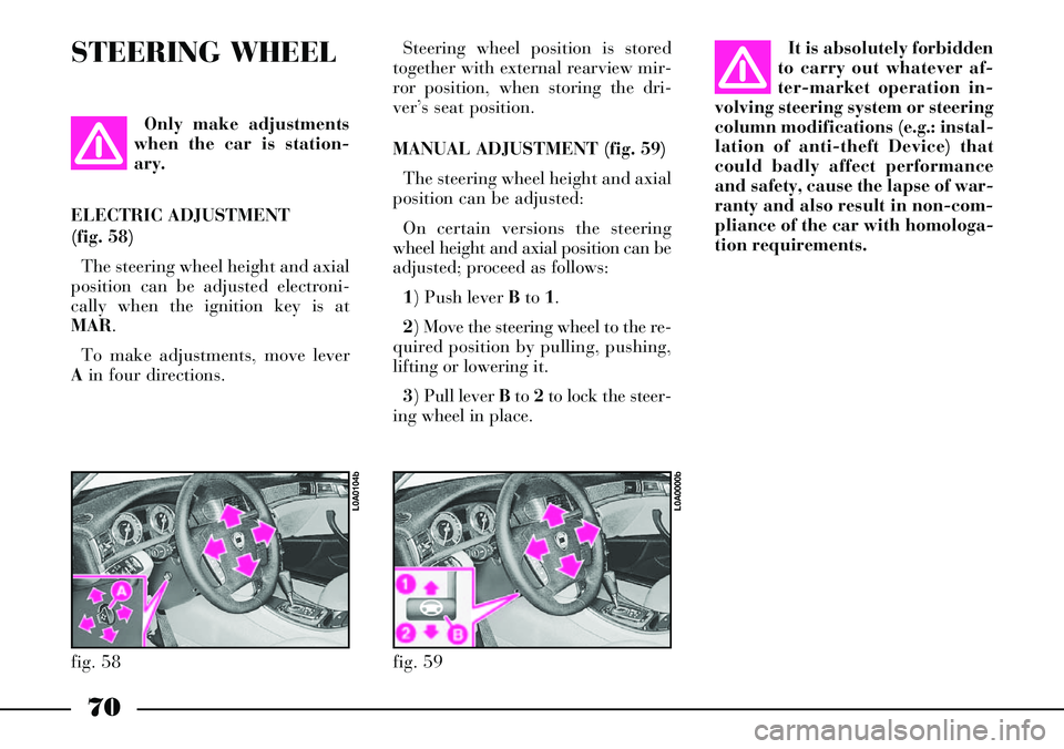
MANUAL ADJUSTMENT (fig. 59)
The steering wheel height and axial
position can be adjusted:
On certain versions the steering
wheel height and axial position can be
adjusted; proceed as follows:
1) Push lever Bto 1.
2) Move the steering wheel to the re-
quired position by pulling, pushing,
lifting or lowering it.
3) Pull leverBto 2to lock the steer-
ing wheel in place. Only make adjustments
when the car is station-
ary.
ELECTRIC ADJUSTMENT
(fig. 58)
The steering wheel height and axial
position can be adjusted electroni-
cally when the ignition key is at
MAR.
To make adjustments, move lever
Ain four directions.
fig. 58
L0A0104b
fig. 59
L0A0000b
Page 78 of 386
77
When the car is parked on a steep
slope the reel mechanism may block;
this is normal. The reel mechanism
prevents the webbing coming out
when it is jerked or if the car brakes
sharply, in a collision or when cor-
nering at high speed.
The rear seat is fitted with inertial
seat belts with three anchor points
and reel for the side and centre
seats.
Rear seat belts shall be worn as
shown in fig. 70.
To prevent incorrect fastening, the
tongues of the side seats and the
buckle of the centre lap belt are
incompatible.
fig. 71
L0A0096b
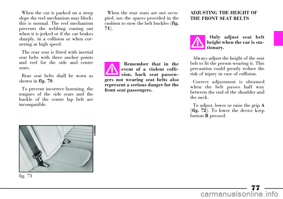
When the rear seats are not occu-
pied, use the spaces provided in the
cushion to stow the belt buckles (fig.
71).
Remember that in the
event of a violent colli-
sion, back seat passen-
gers not wearing seat belts also
represent a serious danger for the
front seat passengers.ADJUSTING THE HEIGHT OF
THE FRONT SEAT BELTS
Only adjust seat belt
height when the car is sta-
tionary.
Always adjust the height of the seat
belt to fit the person wearing it. This
precaution could greatly reduce the
risk of injury in case of collision.
Correct adjustment is obtained
when the belt passes half way
between the end of the shoulder and
the neck.
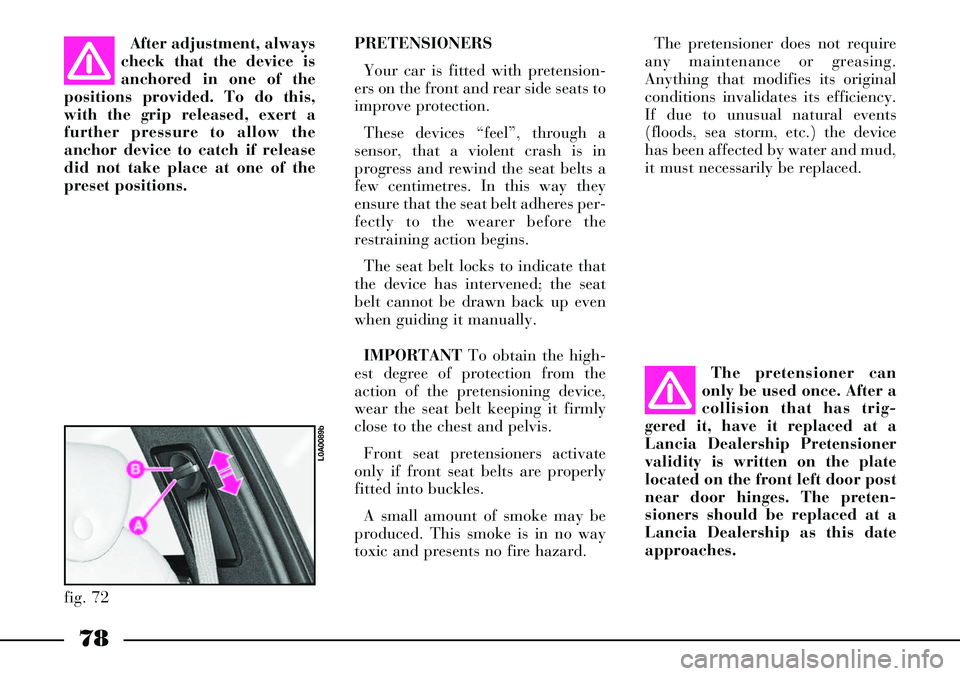
To adjust, lower or raise the grip A
(fig. 72). To lower the device keep
button Bpressed.
Page 79 of 386
78
The pretensioner does not require
any maintenance or greasing.
Anything that modifies its original
conditions invalidates its efficiency.
If due to unusual natural events
(floods, sea storm, etc.) the device
has been affected by water and mud,
it must necessarily be replaced.
The pretensioner can
only be used once. After a
collision that has trig-
gered it, have it replaced at a
Lancia Dealership Pretensioner
validity is written on the plate
located on the front left door post
near door hinges. The preten-
sioners should be replaced at a
Lancia Dealership as this date
approaches.After adjustment, always
check that the device is
anchored in one of the
positions provided. To do this,
with the grip released, exert a
further pressure to allow the
anchor device to catch if release
did not take place at one of the
preset positions. PRETENSIONERS
Your car is fitted with pretension-
ers on the front and rear side seats to
improve protection.
These devices “feel”, through a
sensor, that a violent crash is in
progress and rewind the seat belts a
few centimetres. In this way they
ensure that the seat belt adheres per-
fectly to the wearer before the
restraining action begins.
The seat belt locks to indicate that
the device has intervened; the seat
belt cannot be drawn back up even
when guiding it manually.
IMPORTANTTo obtain the high-
est degree of protection from the
action of the pretensioning device,
wear the seat belt keeping it firmly
close to the chest and pelvis.
Front seat pretensioners activate
only if front seat belts are properly
fitted into buckles.
A small amount of smoke may be
produced. This smoke is in no way
toxic and presents no fire hazard.
fig. 72
L0A0089b
Page 88 of 386
87
fig. 84
L0A0420b
fig. 85
L0A0255b
For proper mounting, proceed as
follows:
– remove the upper tether on the
back of the child's restraint system;
– check whether the release lever B
(fig. 83) is at rest position (inward);– identify the brackets A(fig. 83)
and mount the child restraint system
with the retainers C(fig. 83) aligned
to the brackets;
– push the child restraint system
until hearing the locking clicks;
– check for proper locking by mov-
ing the child's seat with force: the
built-in safety mechanism actually
inhibit improper coupling with just
one coupling locked;
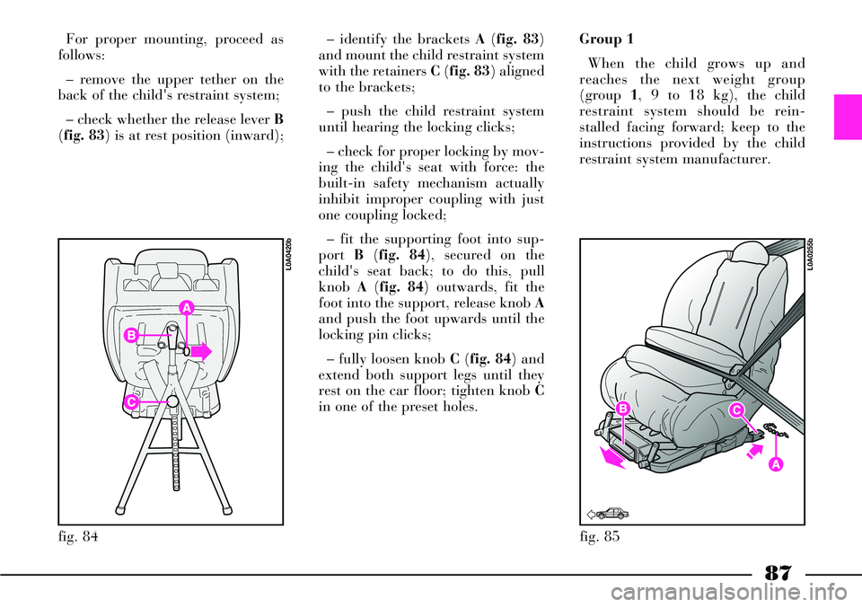
– fit the supporting foot into sup-
port B(fig. 84), secured on the
child's seat back; to do this, pull
knob A(fig. 84) outwards, fit the
foot into the support, release knob A
and push the foot upwards until the
locking pin clicks;
– fully loosen knob C(fig. 84) and
extend both support legs until they
rest on the car floor; tighten knob C
in one of the preset holes.Group 1
When the child grows up and
reaches the next weight group
(group 1, 9 to 18 kg), the child
restraint system should be rein-
stalled facing forward; keep to the
instructions provided by the child
restraint system manufacturer.
Page 89 of 386
88
FRONT AND SIDE
AIRBAGS
The car is equipped with front
(Multistage) airbags for the driver
(fig. 86) and passenger B(fig. 87),
front side bags C (fig. 88), window
bags D(fig. 89) and (where provid-
ed) rear side bags E(fig. 90).
“SMART BAG” SYSTEM
(FRONT MULTISTAGE AIRBAGS)
Description and operation
The front air bag (driver and pas-
senger) is a safety device which
comes into action in the event of a
front/angled impact.
fig. 86
L0A0067b
For proper mounting, proceed as
follows:
– remove the upper tether on the
back of the child's restraint system;
– remove the black plate on the
child's seat back and loosen the
three knob screws completely;
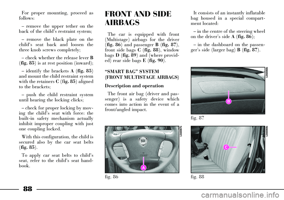
– check whether the release lever B
(fig. 85) is at rest position (inward);
– identify the brackets A(fig. 85)
and mount the child restraint system
with the retainers C(fig. 85) aligned
to the brackets;
– push the child restraint system
until hearing the locking clicks;
– check for proper locking by mov-
ing the child's seat with force: the
built-in safety mechanism actually
inhibit improper coupling with just
one coupling locked.
With this configuration, the child is
secured also by the car seat belts
(fig. 85).
To apply car seat belts to child's
seat, refer to the child's seat hand-
book.It consists of an instantly inflatable
bag housed in a special compart-
ment located:
– in the centre of the steering wheel
on the driver’s side A (fig. 86);
– in the dashboard on the passen-
ger’s side (larger bag) B(fig. 87).
fig. 87
L0A0068b
fig. 88
L0A0069b
Page 111 of 386
110
KILOMETRE COUNTER (AND
TRIP METER) AND AUTOMATIC
GEARBOX
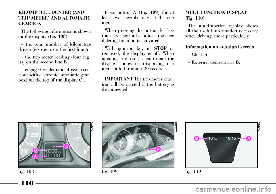
The following information is shown
on the display (fig. 108):
– the total number of kilometres
driven (six digits on the first line A;
– the trip meter reading (four dig-
its) on the second line B ;
– engaged or demanded gear (ver-
sions with electronic automatic gear-
box) on the top of the display C .Press button A(fig. 109) for at
least two seconds to reset the trip
meter.
When pressing the button for less
than two seconds, failure message
deleting function is activated.
With ignition key at STOPor
removed, the display is off. When
opening or closing a front door, the
display comes on displaying trip
meter info for about 20 seconds.
IMPORTANTThe trip meter read-
ing will be deleted if the battery is
disconnected.
fig. 108
L0A0237b
fig. 109
L0A0092b
MULTIFUNCTION DISPLAY
(fig. 110)
The multifunction display shows
all the useful information necessary
when driving, more particularly:
Information on standard screen
– Clock A
– External temperature B.
fig. 110
L0A0258b
Page 120 of 386
119
ABS SYSTEM FAILURE
Turning the ignition key
to MAR, the instrument
panel warning light turns on but it
should go off after a few seconds.
When there is failure the warning
light stays on or comes on when
travelling together with message
“ABS SYSTEM FAULT” on the
multifunction display. In this case
the braking system keeps its effec-
tiveness unchanged, but without the
potential offered by the ABS system.
It is however recommended to con-
tact a Lancia Dealershipas soon
as possible.
In the event of instrument panel
warning light failure, the warning
light on the multifunction display
comes on together with message
“ABS INDICATOR FAULT”: con-
tact a Lancia Dealership as soon
as possible.In this case heavy brak-
ing may cause the rear
wheels to lock before
time, with the possibility of skid-
ding, stop the car immediately
and contact a Lancia Dealership.
>
EBD SYSTEM
FAULT
(ELECTRONIC
BRAKEFORCE DISTRIBUTOR)
The car is fitted with electronic
braking distributor (EBD). The
turning on at the same time of the
xand >warning lights on the
instrument panel together with mes-
sage “EBD SYSTEM FAULT” on
the multifunction display with the
engine running indicates an EBD
system failure.
x>
If the xwarning light
comes on when travelling,
stop immediately and
contact a Lancia Dealership.
In the event of instrument panel
warning light failure, the warning
light on the multifunction display
comes on together with message
“BRAKE FLUID INDICATOR
FAULT”: contact a Lancia
Dealership as soon as possible.
Page 123 of 386

122
Follow me home device
Warning light/symbol
-
Instrument dimmer
Warning light/symbol
x
Meaning of the message
Indicates the set lighting
level (for instrument panel,
display and buttons)
Meaning of the message
Indicates that the “Follow me
home” device is on, external
lights will therefore stay on
for the set time Remarks
–
Remarks
Minimum: 30 seconds,
maximum: 210 seconds, 30
seconds intervals
Steering wheel lock
Warning light/symbol
-
Message
FOLLOW ME
XXs Message
STEERING LOCKED WHEN
DOORS CLOSEDMeaning of the message
Steering will be locked when
locking the doors
with the remote controlRemarks
– Message
DIMMER
INSTRUMENT