warning light Lancia Voyager 2012 Owner handbook (in English)
[x] Cancel search | Manufacturer: LANCIA, Model Year: 2012, Model line: Voyager, Model: Lancia Voyager 2012Pages: 344, PDF Size: 3.95 MB
Page 117 of 344

While sitting in the seat, pull up on
the handle and slide the seat forward
or rearward. Release the bar once you
have reached the desired position.
Then, using body pressure, move for-
ward and rearward on the seat to be
sure that the seat adjusters have
latched.WARNING!
Adjusting a seat while drivingmay be dangerous. Moving a seat
while driving could result in loss
of control which could cause a
collision and serious injury or
death.
(Continued)
WARNING!(Continued)
Seats should be adjusted before
fastening the seat belts and while
the vehicle is parked. Serious in-
jury or death could result from a
poorly adjusted seat belt.
Manual Recline
To recline, lean forward slightly, lift
the lever, then push back to the de-
sired position and release the lever.
Lean forward and lift the lever to
return the seatback to its normal po-
sition. Using body pressure, lean for-
ward and rearward on the seat to be
sure the seatback has latched.
WARNING!
Do not ride with the seatback re-
clined so that the shoulder belt is no
longer resting against your chest. In
a collision you could slide under the
seat belt, which could result in seri-
ous injury or death.
Fold-Flat
To fold the seat, lift the recliner lever
to the full upward position and push
the seatback forward until it rests on
the seat cushion.
Manual Seat Adjuster
Recline Lever
Fold-Flat Quad Seat
111
Page 125 of 344
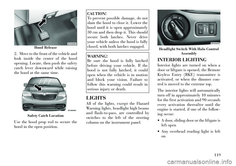
2. Move to the front of the vehicle and
look inside the center of the hood
opening. Locate, then push the safety
catch lever downward while raising
the hood at the same time.
Use the hood prop rod to secure the
hood in the open position.
CAUTION!
To prevent possible damage, do not
slam the hood to close it. Lower the
hood until it is open approximately
30 cm and then drop it. This should
secure both latches. Never drive
your vehicle unless the hood is fully
closed, with both latches engaged.WARNING!
Be sure the hood is fully latched
before driving your vehicle. If the
hood is not fully latched, it could
open when the vehicle is in motion
and block your vision. Failure to
follow this warning could result in
serious injury or death.
LIGHTS
All of the lights, except the Hazard
Warning lights, headlight high beams
and flash-to-pass, are controlled by
switches to the left of the steering
column on the instrument panel. INTERIOR LIGHTING
Interior lights are turned on when a
door or liftgate is opened, the Remote
Keyless Entry (RKE) transmitter is
activated, or when the dimmer con-
trol is moved to the extreme top.
The interior lights will automatically
turn off in approximately 10 minutes
for the first activation and 90 seconds
every activation thereafter until the
engine is started, if one of the follow-
ing occur:
A door, sliding door or the liftgate is
left open
Any overhead reading light is left on
Hood Release
Safety Catch Location
Headlight Switch With Halo Control Assembly
119
Page 129 of 344

TURN SIGNALS
Move the multifunction lever up or
down and the arrows on each side of
the instrument cluster flash to show
proper operation of the front and rear
turn signal lights.
NOTE:
If either light remains on and does
not flash, or there is a very fast
flash rate, check for a defective
outside light bulb. If an indicator
fails to light when the lever is
moved, it would suggest that the
indicator bulb is defective.
Lane Change Assist
Tap the lever up or down once, with-
out moving beyond the detent, and
the turn signal (right or left) will flash
three times then automatically turn
off.
Turn Signal Warning
If the vehicle electronics sense that the
vehicle has traveled at over 29 km/h
for approximately 1.6 km with the
turn signals on, a chime will sound to
alert the driver.HIGH/LOW BEAM SWITCH
When the headlights are turned on,
pushing the multifunction lever to-
ward the instrument panel will switch
from low beams to high beams. Pull-
ing back to the neutral position re-
turns the headlights to the low beam
operation.
FLASH-TO-PASS
You can signal another vehicle with
your headlights by lightly pulling the
multifunction lever toward you. This
will turn on the high beam headlights
until the lever is released.
SMARTBEAM™ (for
versions/markets, where
provided)
The SmartBeam™ system provides
increased forward lighting at night by
automating high beam control
through the use of a digital camera
mounted on the inside rearview mir-
ror. This camera detects vehicle spe-
cific light and automatically switches
from high beams to low beams until
the approaching vehicle is out of view.To Activate
1. Select “Automatic High Beams —
ON” through the EVIC. Refer to
“Electronic Vehicle Information Cen-
ter (EVIC)/Customer-Programmable
Features” in “Understanding Your In-
strument Panel” for further informa-
tion.
2. Rotate the headlight switch coun-
terclockwise to the AUTO (A) posi-
tion.
3. Push the multifunction lever away
from you to switch the headlights to
the high beam position. Refer to
“Multifunction Lever” in this section
for further information.
NOTE:
This system will not activate until
the vehicle is at, or above, 40 km/h.
To Deactivate
Perform either of the following steps
to deactivate the SmartBeam™ sys-
tem.
1. Select “Automatic High Beams —
OFF” through the EVIC. Refer to
“Electronic Vehicle Information Cen-
ter (EVIC)/Customer-Programmable
123
Page 134 of 344

CAUTION!
Do not place any article under the
adjustable pedals or impede its abil-
ity to move, as it may cause damage
to the pedal controls. Pedal travel
may become limited if movement is
stopped by an obstruction in the ad-
justablepedal's path.WARNING!
Do not adjust the pedals while the
vehicle is moving. You could lose
control and have an accident. Al-
ways adjust the pedals while the ve-
hicle is parked.
ELECTRONIC SPEED
CONTROL (for
versions/markets, where
provided)
When engaged, the Electronic Speed
Control takes over accelerator opera-
tions at speeds greater than 40 km/h.
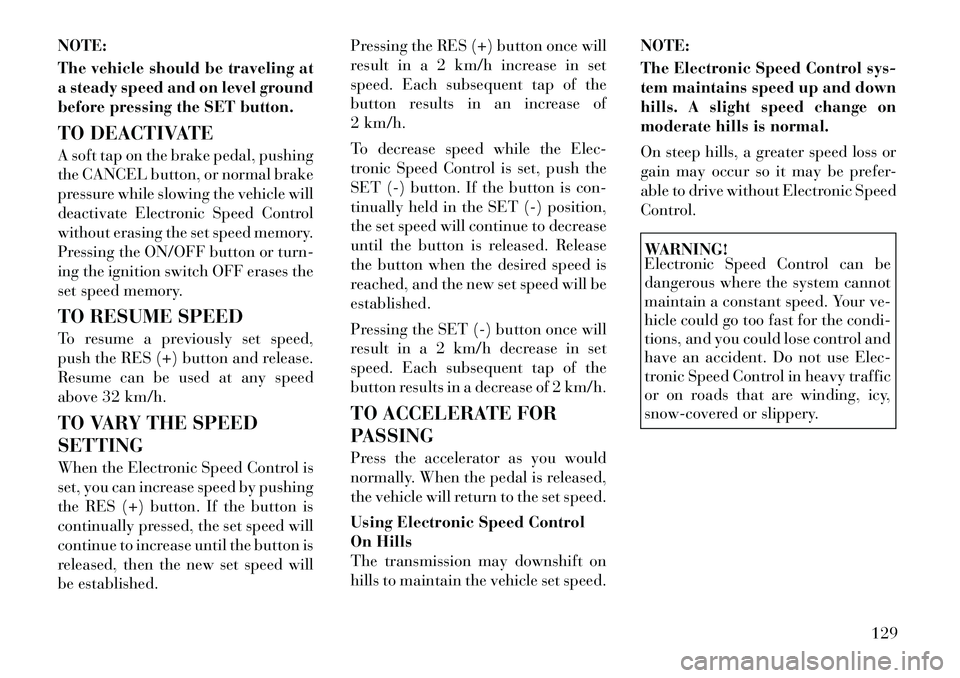
The Electronic Speed Control buttons
are located on the right side of the
steering wheel. NOTE:
In order to ensure proper opera-
tion, the Electronic Speed Control
System has been designed to shut
down if multiple Speed Control
functions are operated at the same
time. If this occurs, the Electronic
Speed Control System can be reac-
tivated by pushing the Electronic
Speed Control ON/OFF button and
resetting the desired vehicle set
speed.TO ACTIVATE
Push the ON/OFF button. The Cruise
Indicator Light in the instrument
cluster will illuminate. To turn the
system off, push the ON/OFF button
a second time. The Cruise Indicator
Light will turn off. The system should
be turned off when not in use.
WARNING!
Leaving the Electronic Speed Con-
trol system on when not in use is
dangerous. You could accidentally
set the system or cause it to go faster
than you want. You could lose con-
trol and have an accident. Always
leave the system OFF when you are
not using it.
TO SET A DESIRED SPEED
Turn the Electronic Speed Control
ON. When the vehicle has reached the
desired speed, press the SET (-) but-
ton and release. Release the accelera-
tor and the vehicle will operate at the
selected speed.
1 — ON/OFF 2 — RES +
4 — CANCEL 3 — SET -
128
Page 135 of 344
NOTE:
The vehicle should be traveling at
a steady speed and on level ground
before pressing the SET button.
TO DEACTIVATE
A soft tap on the brake pedal, pushing
the CANCEL button, or normal brake
pressure while slowing the vehicle will
deactivate Electronic Speed Control
without erasing the set speed memory.
Pressing the ON/OFF button or turn-
ing the ignition switch OFF erases the
set speed memory.
TO RESUME SPEED
To resume a previously set speed,
push the RES (+) button and release.
Resume can be used at any speed
above 32 km/h.
TO VARY THE SPEED
SETTING
When the Electronic Speed Control is
set, you can increase speed by pushing
the RES (+) button. If the button is
continually pressed, the set speed will
continue to increase until the button is
released, then the new set speed will
be established.Pressing the RES (+) button once will
result in a 2 km/h increase in set
speed. Each subsequent tap of the
button results in an increase of
2 km/h.
To decrease speed while the Elec-
tronic Speed Control is set, push the
SET (-) button. If the button is con-
tinually held in the SET (-) position,
the set speed will continue to decrease
until the button is released. Release
the button when the desired speed is
reached, and the new set speed will be
established.
Pressing the SET (-) button once will
result in a 2 km/h decrease in set
speed. Each subsequent tap of the
button results in a decrease of 2 km/h.
TO ACCELERATE FOR
PASSING
Press the accelerator as you would
normally. When the pedal is released,
the vehicle will return to the set speed.
Using Electronic Speed Control
On Hills
The transmission may downshift on
hills to maintain the vehicle set speed.
NOTE:
The Electronic Speed Control sys-
tem maintains speed up and down
hills. A slight speed change on
moderate hills is normal.
On steep hills, a greater speed loss or
gain may occur so it may be prefer-
able to drive without Electronic Speed
Control.
WARNING!
Electronic Speed Control can be
dangerous where the system cannot
maintain a constant speed. Your ve-
hicle could go too fast for the condi-
tions, and you could lose control and
have an accident. Do not use Elec-
tronic Speed Control in heavy traffic
or on roads that are winding, icy,
snow-covered or slippery.
129
Page 142 of 344

WARNING!
Drivers must be careful when back-
ing up even when using the
ParkView® Rear Back Up Camera.
Always check carefully behind your
vehicle, and be sure to check for
pedestrians, animals, other vehicles,
obstructions, or blind spots before
backing up. You are responsible for
the safety of your surroundings and
must continue to pay attention while
backing up. Failure to do so can
result in serious injury or death.CAUTION!
To avoid vehicle damage,ParkView® should only be used
as a parking aid. The camera is
unable to view every obstacle or
object in your drive path.
To avoid vehicle damage, the ve-
hicle must be driven slowly when
using ParkView® to be able to
stop in time when an obstacle is
seen. It is recommended that the
driver look frequently over his/
her shoulder when using
ParkView®. NOTE:
If snow, ice, mud, or any foreign
substance builds up on the camera
lens, clean the lens, rinse with wa-
ter, and dry with a soft cloth. Do
not cover the lens.
TURNING PARKVIEW® ON
OR OFF — WITH
NAVIGATION/
MULTIMEDIA RADIO
1. Press the “menu” hard-key.
2. Select “system setup” soft-key.
3. Press the “camera setup” soft-key.
4. Enable or disable the rear camera
feature by selecting “enable rear cam-
era in reverse” soft-key.
5. Press the “save” soft-key.
TURNING PARKVIEW® ON
OR OFF — WITHOUT
NAVIGATION/
MULTIMEDIA RADIO
1. Press the “menu” hard-key.
2. Select “system setup” soft-key.
3. Enable or disable the rear camera
feature by selecting “enable rear cam-
era in reverse” soft-key.
OVERHEAD CONSOLES
FRONT OVERHEAD
CONSOLE
Two versions of the overhead console
are available. The base front overhead
console model featured fixed incan-
descent courtesy/reading lights, flip-
down sunglass storage and conversa-
tion mirror. The premium front
overhead console model features a
LED focused light that illuminates
the instrument panel cupholders, two
swiveling LED lights, flip-down sun-
glass storage, conversation mirror,
optional power sliding door switches
and an optional power liftgate switch.
NOTE:
Premium sunroof console models
include all of above except sun-
glass storage.
136
Page 148 of 344
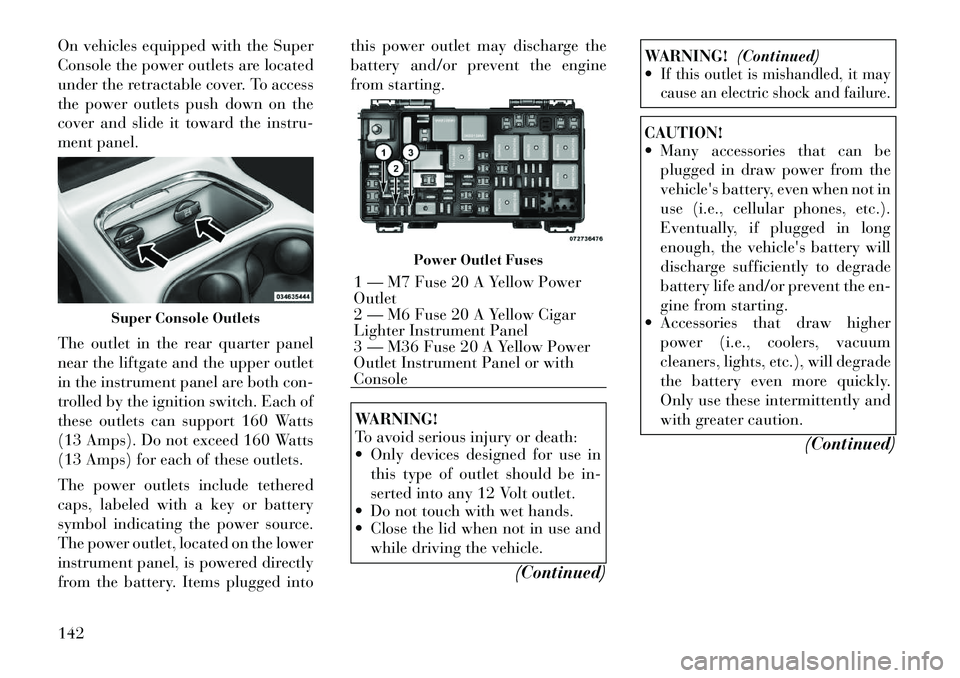
On vehicles equipped with the Super
Console the power outlets are located
under the retractable cover. To access
the power outlets push down on the
cover and slide it toward the instru-
ment panel.
The outlet in the rear quarter panel
near the liftgate and the upper outlet
in the instrument panel are both con-
trolled by the ignition switch. Each of
these outlets can support 160 Watts
(13 Amps). Do not exceed 160 Watts
(13 Amps) for each of these outlets.
The power outlets include tethered
caps, labeled with a key or battery
symbol indicating the power source.
The power outlet, located on the lower
instrument panel, is powered directly
from the battery. Items plugged intothis power outlet may discharge the
battery and/or prevent the engine
from starting.
WARNING!
To avoid serious injury or death:
Only devices designed for use in
this type of outlet should be in-
serted into any 12 Volt outlet.
Do not touch with wet hands.
Close the lid when not in use and
while driving the vehicle.
(Continued)
WARNING!(Continued)
If this outlet is mishandled, it may
cause an electric shock and failure.CAUTION!
Many accessories that can be
plugged in draw power from the
vehicle's battery, even when not in
use (i.e., cellular phones, etc.).
Eventually, if plugged in long
enough, the vehicle's battery will
discharge sufficiently to degrade
battery life and/or prevent the en-
gine from starting.
Accessories that draw higher
power (i.e., coolers, vacuum
cleaners, lights, etc.), will degrade
the battery even more quickly.
Only use these intermittently and
with greater caution.
(Continued)
Super Console Outlets
Power Outlet Fuses
1 — M7 Fuse 20 A Yellow Power
Outlet
2 — M6 Fuse 20 A Yellow Cigar
Lighter Instrument Panel
3 — M36 Fuse 20 A Yellow Power
Outlet Instrument Panel or with
Console
142
Page 154 of 344

CENTER AND REAR
OVERHEAD CONSOLE
STORAGE (for
version/markets, where
provided)
The overhead storage system comes in
several options.COAT HOOKS
Coat hooks are located along the
headliner for the second and third row
seating positions. The coat hook load
limit is 4.5 kg . Exceeding the recom-
mended load limit can cause the coat
hooks to break or disengage from the
vehicle.
CARGO AREA STORAGE
The liftgate sill plate has a raised line
with the statement “Load To This
Line”. This line indicates how far
rearward cargo can be placed without
interfering with liftgate closing.
NOTE:
With all rear seats stowed or re-
moved, 4 x 8 foot sheets of building
material will fit on the vehicle
floor with the liftgate closed. Thefront seats must be moved slightly
forward of the rearmost position.
In addition to the rear cargo area, on
some models there are open storage
areas located in the rear trim panels.
CONSOLE FEATURES
There are three consoles available:
Basic, Premium and Super.
WARNING!
Do not operate this vehicle with a
console compartment lid in the open
position. Cellular phones, music
players, and other handheld elec-
tronic devices should be stowed
while driving. Use of these devices
while driving can cause an accident
due to distraction, resulting in death
or injury.
Overhead Console Features
1 — DVD
1
5 — Storage
2 — Rear HVAC 6 — DVD
1
3 — Courtesy
Lights 7 — Courtesy
Lights
4 — Storage 8 — Halo Light- ing1(for versions/markets, where pro-
vided)
Rear Cargo Area Loading Limit
Trim Panel Storage Area
148
Page 155 of 344

BASIC CONSOLE
Basic Console features consist of the
following:
The basic console profile allows ve-hicle occupants to easily pass
through the first row to the second.
Four cupholders accept up to extra large size beverage cups or 20 oz
(.6 L) plastic bottles. Cupholders
are dishwasher safe for cleaning.
The cupholders are removable to access a large storage bin.
The basic console is removable from the vehicle for additional floor
space by removing the cap and clip
at the console base.
To Remove The Basic Floor
Console
1. Remove the front anchor cup plug
and clip.
2. Slide the console base forward
while lifting slightly to clear the rear
load floor hook.
3. Remove the console. To Reinstall The Basic Floor
Console
1. Position the console at a slight
angle (front slightly higher than the
rear).
2. Slide the console rearward into the
floor bracket/hook.
3. Align the console until the front
anchor cup plug hole is centered on
the winch hole.
4. Reinstall the clip first and then
while pushing downward on the con-
sole with slight pressure, reinstall the
cover plug.
5. Pull up on the console to be sure it
is firmly latched.
WARNING!
In an accident, serious injury could
result if the removable floor console
is not properly installed. Always be
sure the removable floor console is
fully latched.
PREMIUM CONSOLE (for
versions/markets, where
provided)
The three-compartment console with
sliding storage bin, sliding upper tray
with storage and large console storage
bin offers multiple configurations.
Four cupholders with dishwasher
safe liners for cleaning. The cup-
holders can accept plastic bottles,
large cups or mugs with handles.
Top tray storage
Upper storage bin can hold nine regular or 18 thin CDs or other
items
Large console center storage will store headphones for the available
rear DVD entertainment system or
other items
12 Volt DC power outlet provides continuous power inside the con-
sole for cell phones or other elec-
tronics.
Rear occupant accessible
Multiple adjustments
149
Page 157 of 344

2. Slide the console forward into the
floor bracket.
3. Rotate the rear of the console down
until it is resting on the floor bracket.
4. Push down on the rear of the con-
sole until it is seated in the rear floor
bracket.
5. Pull up on the console to be sure it
is firmly latched.WARNING!
In an accident, serious injury could
result if the removable floor console
is not properly installed. Always be
sure the removable floor console is
fully latched.
SUPER CONSOLE (for
versions/markets, where
provided)
The Super Console contains multiple
storage areas, front lower pass
through, top forward bin, top rear-
ward bin and rear pull out drawer.
The super console contains a pass
through storage area accessible for
both the driver and front passenger. The super console tambour doors are
opened by pushing down on the finger
tabs and sliding the door. The front
tambour door slides forward, the rear
tambour door slides rearward.
NOTE:
The front cupholder light ring and
pass through lighting is controlled
by a dimming switch located on
the instrument panel, refer to
“Lights” in “Understanding The
Features Of Your Vehicle” for fur-
ther information.
Located in the back of the super con-
sole is a storage drawer and cuphold-
ers for the rear passengers.
Front Lower Pass Through
Super Console
1 — Front Sliding Tambour Door
2 — Cupholder Light Ring
3 — Rear Sliding Tambour Door
Rear Drawer Storage
151