warning light Lancia Voyager 2012 Owner handbook (in English)
[x] Cancel search | Manufacturer: LANCIA, Model Year: 2012, Model line: Voyager, Model: Lancia Voyager 2012Pages: 344, PDF Size: 3.95 MB
Page 70 of 344

body areas for broken, damaged, de-
teriorated, or mispositioned parts.
Open seams or loose connections
could permit exhaust fumes to seep
into the passenger compartment. In
addition, inspect the exhaust system
each time the vehicle is raised for lu-
brication or oil change. Replace as
required.
Safety Checks You Should
Make Inside The Vehicle
Seat Belts
Inspect the belt system periodically,
checking for cuts, frays, and loose
parts. Damaged parts must be re-
placed immediately. Do not disas-
semble or modify the system.
Front seat belt assemblies must be
replaced after a collision. Rear seat
belt assemblies must be replaced after
a collision if they have been damaged
(i.e., bent retractor, torn webbing,
etc.). If there is any question regard-
ing belt or retractor condition, replace
the belt.Air Bag Warning Light
The light should come on and remain
on for four to eight seconds as a bulb
check when the ignition switch is first
turned ON. If the light is not lit during
starting, see your authorized dealer. If
the light stays on, flickers, or comes
on while driving, have the system
checked by an authorized dealer.
Defroster
Check operation by selecting the de-
frost mode and place the blower con-
trol on high speed. You should be able
to feel the air directed against the
windshield. See your authorized
dealer for service if your defroster is
inoperable.
Floor Mat Safety Information
Always use floor mats designed to fit
the footwell of your vehicle. Use only
floor mats that leave the pedal area
unobstructed and that are firmly se-
cured so that they cannot slip out of
position and interfere with the pedals
or impair safe operation of your ve-
hicle in other ways.
WARNING!
Pedals that cannot move freely can
cause loss of vehicle control and in-
crease the risk of serious personal
injury.
Always make sure that floor mats
are properly attached to the floor
mat fasteners.
Never place or install floor mats or
other floor coverings in the vehicle
that cannot be properly secured to
prevent them from moving and
interfering with the pedals or the
ability to control the vehicle.
Never put floor mats or other floor
coverings on top of already in-
stalled floor mats. Additional
floor mats and other coverings
will reduce the size of the pedal
area and interfere with the pedals.
Check mounting of mats on a
regular basis. Always properly re-
install and secure floor mats that
have been removed for cleaning.
(Continued)
64
Page 71 of 344

WARNING!(Continued)
Always make sure that objects
cannot fall into the driver footwell
while the vehicle is moving. Ob-
jects can become trapped under
the brake pedal and accelerator
pedal causing a loss of vehicle
control.
If required, mounting posts must
be properly installed, if not
equipped from the factory.
Failure to properly follow floor mat
installation or mounting can cause
interference with the brake pedal
and accelerator pedal operation
causing loss of control of the vehicle. Periodic Safety Checks You
Should Make Outside The
Vehicle
Tires
Examine tires for excessive tread wear
and uneven wear patterns. Check for
stones, nails, glass, or other objects
lodged in the tread or sidewall. In-
spect the tread for cuts and cracks.
Inspect sidewalls for cuts, cracks and
bulges. Check the wheel nuts for
tightness. Check the tires (including
spare) for proper cold inflation pres-
sure.
Lights
Have someone observe the operation
of exterior lights while you work the controls. Check turn signal and high
beam indicator lights on the instru-
ment panel.
Door Latches
Check for positive closing, latching,
and locking.
Fluid Leaks
Check area under vehicle after over-
night parking for fuel, engine coolant,
oil, or other fluid leaks. Also, if gaso-
line fumes are detected or if fuel,
power steering fluid, or brake fluid
leaks are suspected, the cause should
be located and corrected immediately.
65
Page 77 of 344

HEADLIGHT WASHER (for versions/markets,where provided) . . . . . . . . . . . . . . . . . . . . . . . . . 126
TILT/TELESCOPING STEERING COLUMN . . . . 127
ADJUSTABLE PEDALS (for versions/markets, where provided) . . . . . . . . . . . . . . . . . . . . . . . . . 127
ELECTRONIC SPEED CONTROL (for versions/markets, where provided) . . . . . . . . . . 128
TO ACTIVATE . . . . . . . . . . . . . . . . . . . . . . . . 128
TO SET A DESIRED SPEED . . . . . . . . . . . . . 128
TO DEACTIVATE . . . . . . . . . . . . . . . . . . . . . . 129
TO RESUME SPEED . . . . . . . . . . . . . . . . . . . 129
TO VARY THE SPEED SETTING . . . . . . . . . . 129
TO ACCELERATE FOR PASSING . . . . . . . . . . 129
PARKSENSE® REAR PARK ASSIST (for versions/markets, where provided) . . . . . . . . . . 130
PARKSENSE® SENSORS . . . . . . . . . . . . . . . . 130
PARKSENSE® WARNING DISPLAY . . . . . . . . 130
PARKSENSE® DISPLAY . . . . . . . . . . . . . . . . 131
ENABLING/DISABLING PARKSENSE® . . . . . 132
SERVICE THE PARKSENSE® REAR PARK ASSIST SYSTEM . . . . . . . . . . . . . . . . . . . . . . 132
CLEANING THE PARKSENSE® SYSTEM . . . 133
PARKSENSE® SYSTEM USAGE PRECAUTIONS . . . . . . . . . . . . . . . . . . . . . . . 133
PARKVIEW® REAR BACK UP CAMERA (for versions/markets, where provided) . . . . . . . . . . 135
71
Page 81 of 344

MIRRORS
INSIDE DAY/NIGHT
MIRROR (for versions/
markets, where provided)
A two-point pivot system allows for
horizontal and vertical adjustment of
the mirror. Adjust the mirror to center
on the view through the rear window.
Headlight glare can be reduced by
moving the small control under the
mirror to the night position (toward
the rear of the vehicle). The mirror
should be adjusted while set in the day
position (toward the windshield).AUTOMATIC DIMMING
MIRROR (for versions/
markets, where provided)
This mirror automatically adjusts for
headlight glare from vehicles behind
you. You can turn the feature on or off
by pressing the button at the base of
the mirror. A light to the left of the
button will illuminate to indicate
when the dimming feature is acti-
vated. The sensor to the right of the
button does not illuminate.
NOTE:
This feature is disabled when the
vehicle is moving in reverse.
CAUTION!
To avoid damage to the mirror dur-
ing cleaning, never spray any clean-
ing solution directly onto the mirror.
Apply the solution onto a clean cloth
and wipe the mirror clean.
OUTSIDE MIRRORS
To receive maximum benefit, adjust
the outside mirror(s) to center on the
adjacent lane of traffic with a slight
overlap of the view obtained on the
inside mirror.WARNING!
Vehicles and other objects seen in an
outside convex mirror will look
smaller and farther away than they
really are. Relying too much on side
convex mirrors could cause you to
collide with another vehicle or other
object. Use your inside mirror when
judging the size or distance of a ve-
hicle seen in a side convex mirror.
Manual Rearview Mirror
Automatic Dimming Mirror
75
Page 84 of 344

BLIND SPOT
MONITORING (for
versions/markets, where
provided)
The Blind Spot Monitoring (BSM)
system uses two radar-based sensors,
located inside the rear bumper fascia,
to detect highway licensable vehicles
(automobiles, trucks, motorcycles,
etc.) that enter the blind spot zones
from the rear/front/side of the ve-
hicle.
When the vehicle is started, the BSM
warning light will momentarily illu-
minate in both outside rear view mir-
rors to let the driver know that the
system is operational. The BSM sys-
tem sensors operate when the vehicle
is in any forward gear or REVERSEand enters stand-by mode when the
vehicle is in PARK.
The BSM detection zone covers ap-
proximately one lane on both sides of
the vehicle or 3.35 m. The zone starts
at the outside rear view mirror and
extends approximately 6 m to the rear
of the vehicle. The BSM system moni-
tors the detection zones on both sides
of the vehicle when the vehicle speed
reaches approximately 10 km/h or
higher and will alert the driver of ve-
hicles in these areas.
NOTE:
The BSM system does NOT alert
the driver about rapidly ap-
proaching vehicles that are out-
side the detection zones.
The BSM system detection zone DOES NOT change if your ve-
hicle is towing a trailer. There-
fore, visually verify the adjacent
lane is clear for both your ve-
hicle and trailer before making
a lane change. If the trailer or
other object (i.e., bicycle, sports
equipment) extends beyond the
side of your vehicle, this may re-
sult in the BSM warning light remaining illuminated the en-
tire time the vehicle is in a for-
ward gear.
The area on the rear fascia where the
radar sensors are located must remain
free of snow, ice, and dirt/road con-
tamination so that the BSM system
can function properly. Do not block
the area of the rear fascia where the
radar sensors are located with foreign
objects (bumper stickers, bicycle
racks, etc.).
The BSM system notifies the driver of
objects in the detection zones by illu-
minating the BSM warning light lo-
cated in the outside mirrors in addi-
tion to sounding an audible (chime)
alert and reducing the radio volume.
Refer to “Modes Of Operation” for
further information.
Rear Detection Zones
Sensor Locations
78
Page 85 of 344
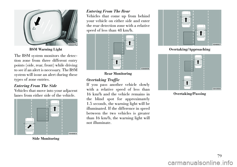
The BSM system monitors the detec-
tion zone from three different entry
points (side, rear, front) while driving
to see if an alert is necessary. The BSM
system will issue an alert during these
types of zone entries.
Entering From The Side
Vehicles that move into your adjacent
lanes from either side of the vehicle.Entering From The Rear
Vehicles that come up from behind
your vehicle on either side and enter
the rear detection zone with a relative
speed of less than 48 km/h.
Overtaking Traffic
If you pass another vehicle slowly
with a relative speed of less than
16 km/h and the vehicle remains in
the blind spot for approximately
1.5 seconds, the warning light will be
illuminated. If the difference in speed
between the two vehicles is greater
than 16 km/h, the warning light will
not illuminate.
BSM Warning LightSide Monitoring
Rear Monitoring
Overtaking/Approaching
Overtaking/Passing
79
Page 87 of 344

WARNING!
RCP is not a Back Up Aid system. It
is intended to be used to help a
driver detect an oncoming vehicle in
a parking lot situation. Drivers must
be careful when backing up, even
when using RCP. Always check care-
fully behind your vehicle, look be-
hind you, and be sure to check for
pedestrians, animals, other vehicles,
obstructions, and blind spots before
backing up. Failure to do so can
result in serious injury or death.
MODES OF OPERATION
Three selectable modes of operation
are available in the Electronic Vehicle
Information Center (EVIC). Refer to
"Electronic Vehicle Information Cen-
ter (EVIC)/Personal Settings
(Customer-Programmable Fea-
tures)” in “Understanding Your In-
strument Panel” for further informa-
tion. Blind Spot Alert
When operating in Blind Spot Alert
mode, the BSM system will provide a
visual alert in the appropriate side
view mirror based on a detected ob-
ject. However, when the system is op-
erating in RCP, the system will re-
spond with both visual and audible
alerts when a detected object is pres-
ent. Whenever an audible alert is re-
quested, the radio is muted.
Blind Spot Alert Lights/Chime
When operating in Blind Spot Alert
Lights/Chime mode, the BSM system
will provide a visual alert in the ap-
propriate side view mirror based on a
detected object. If the turn signal is
then activated, and it corresponds to
an alert present on that side of the
vehicle, an audible chime will also be
sounded. Whenever a turn signal and
detected object are present on the
same side at the same time, both the
visual and audio alerts will be issued.
In addition to the audible alert the
radio (if on) will also be muted.NOTE:
Whenever an audible alert is re-
quested by the BSM system, the
radio is also muted.
If the hazard flashers are on, the system will request the appro-
priate visual alert only.
When the system is in RCP, the
system shall respond with both vi-
sual and audible alerts when a de-
tected object is present. Whenever
an audible alert is requested, the
radio is also muted. Turn/hazard
signal status is ignored; the RCP
state always requests the chime.
Blind Spot Alert Off
When the BSM system is turned off
there will be no visual or audible
alerts from either the BSM or RCP
systems.
NOTE:
The BSM system will store the cur-
rent operating mode when the ve-
hicle is shut off. Each time the ve-
hicle is started the previously
stored mode will be recalled and
used.
81
Page 96 of 344
NOTE:
The default number is 112. Thenumber dialed may not be ap-
plicable with the available mo-
bile service and area.
If supported, this number may be programmable on some sys-
tems. To do this, press thebutton and say “Setup”, fol-
lowed by “Emergency”.
The Uconnect™ Phone does slightly lower your chances of
successfully making a phone
call as to that for the mobile
phone directly.WARNING!
To use your Uconnect™ Phone Sys-
tem in an emergency, your mobile
phone must be:
turned on,
paired to the Uconnect™ System,
and have network coverage.
Breakdown Service (for
versions/markets, where
provided)
If you need Breakdown service:
Press the
button to begin. After the “Ready” prompt and the
following beep, say “Breakdown
service”.
NOTE:
The Breakdown service number
has to be setup before using. To
setup, press the
button and say
“Setup, Breakdown Service” and
follow prompts.
Paging
To learn how to page refer to “Work-
ing with Automated Systems”. Paging
works properly except for pagers of
certain companies which time out a
little too soon to work properly with
the Uconnect™ Phone.
Voice Mail Calling
To learn how to access your voice
mail, refer to “Working with Auto-
mated Systems”.
Working With Automated Systems
This method is used in instances
where one generally has to press num-
bers on the mobile phone keypad
while navigating through an auto-
mated telephone system.
You can use your Uconnect™ Phone
to access a voice mail system or an automated service, such as a paging
service or automated customer ser-
vice. Some services require immediate
response selection. In some instances,
that may be too quick for use of the
Uconnect™ Phone.
When calling a number with your
Uconnect™ Phone that normally re-
quires you to enter in a touch-tone
sequence on your mobile phone key-
pad, you can press the
button
and say the sequence you wish to en-
ter followed by the word “Send”. For
example, if required to enter your PIN
followed with a hash, (3 7 4 6 #), you
can press the
button and say, “3
7 4 6 # Send”. Saying a number, or
sequence of numbers, followed by
“Send”, is also to be used for navigat-
ing through an automated customer
service center menu structure, and to
leave a number on a pager.
You can also send stored Uconnect™
Phonebook entries as tones for fast
and easy access to voice mail and
pager entries. To use this feature, dial
the number you wish to call and then
press thebutton and say
“Send.” The system will prompt you
90
Page 110 of 344
POWER LUMBAR (for
versions/markets, where
provided)
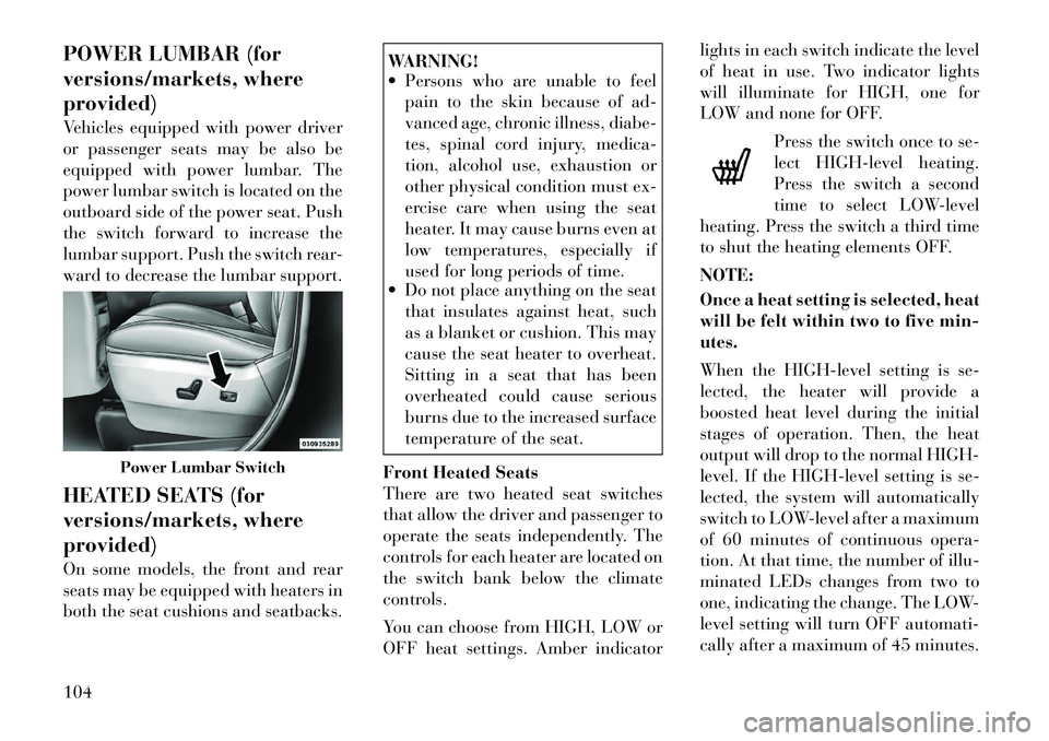
Vehicles equipped with power driver
or passenger seats may be also be
equipped with power lumbar. The
power lumbar switch is located on the
outboard side of the power seat. Push
the switch forward to increase the
lumbar support. Push the switch rear-
ward to decrease the lumbar support.
HEATED SEATS (for
versions/markets, where
provided)
On some models, the front and rear
seats may be equipped with heaters in
both the seat cushions and seatbacks.
WARNING!
Persons who are unable to feel pain to the skin because of ad-
vanced age, chronic illness, diabe-
tes, spinal cord injury, medica-
tion, alcohol use, exhaustion or
other physical condition must ex-
ercise care when using the seat
heater. It may cause burns even at
low temperatures, especially if
used for long periods of time.
Do not place anything on the seat
that insulates against heat, such
as a blanket or cushion. This may
cause the seat heater to overheat.
Sitting in a seat that has been
overheated could cause serious
burns due to the increased surface
temperature of the seat.
Front Heated Seats
There are two heated seat switches
that allow the driver and passenger to
operate the seats independently. The
controls for each heater are located on
the switch bank below the climate
controls.
You can choose from HIGH, LOW or
OFF heat settings. Amber indicator lights in each switch indicate the level
of heat in use. Two indicator lights
will illuminate for HIGH, one for
LOW and none for OFF.
Press the switch once to se-
lect HIGH-level heating.
Press the switch a second
time to select LOW-level
heating. Press the switch a third time
to shut the heating elements OFF.
NOTE:
Once a heat setting is selected, heat
will be felt within two to five min-
utes.
When the HIGH-level setting is se-
lected, the heater will provide a
boosted heat level during the initial
stages of operation. Then, the heat
output will drop to the normal HIGH-
level. If the HIGH-level setting is se-
lected, the system will automatically
switch to LOW-level after a maximum
of 60 minutes of continuous opera-
tion. At that time, the number of illu-
minated LEDs changes from two to
one, indicating the change. The LOW-
level setting will turn OFF automati-
cally after a maximum of 45 minutes.
Power Lumbar Switch
104
Page 112 of 344

WARNING!
Adjusting a seat while drivingmay be dangerous. Moving a seat
while driving could result in loss
of control which could cause a
collision and serious injury or
death.
Seats should be adjusted before
fastening the seat belts and while
the vehicle is parked. Serious in-
jury or death could result from a
poorly adjusted seat belt.
MANUAL RECLINING
SEATS (for versions/
markets, where provided)
For models equipped with manual re-
clining seats, the recline lever is lo-
cated on the outboard side of the seat. To recline, lean forward slightly, lift
the lever, then push back to the de-
sired position and release the lever.
Lean forward and lift the lever to
return the seatback to its normal po-
sition. Using body pressure, lean for-
ward and rearward on the seat to be
sure the seatback has latched.
WARNING!
Do not ride with the seatback re-
clined so that the shoulder belt is no
longer resting against your chest. In
a collision you could slide under the
seat belt, which could result in seri-
ous injury or death.
HEAD RESTRAINTS
Head restraints are designed to reduce
the risk of injury by restricting head
movement in the event of a rear im-
pact. Head restraints should be ad-
justed so that the top of the head
restraint is located above the top of
your ear.
WARNING!
The head restraints for all occupants
must be properly adjusted prior to
operating the vehicle or occupying a
seat. Head restraints should never be
adjusted while the vehicle is in mo-
tion. Driving a vehicle with the head
restraints improperly adjusted or re-
moved could cause serious injury or
death in the event of a collision.
Active Head Restraints — Front
Seats
Active Head Restraints are passive,
deployable components, and vehicles
with this equipment can not be read-
ily identified by any markings, only
through visual inspection of the head
restraint. The head restraint will be
split in two halves, with the front half
being soft foam and trim, the back
half being decorative plastic.
When AHRs deploy during a rear im-
pact, the front half of the head re-
straint extends forward to minimize
the gap between the back of the occu-
pant’s head and the AHR. This system
is designed to help prevent or reduce
the extent of injuries to the driver and
Manual Recline Lever
106