climate control Lancia Voyager 2012 Owner handbook (in English)
[x] Cancel search | Manufacturer: LANCIA, Model Year: 2012, Model line: Voyager, Model: Lancia Voyager 2012Pages: 344, PDF Size: 3.95 MB
Page 39 of 344

When the RKE transmitter button is
pressed and the Flash Lights feature
is enabled, the tail lights will flash and
several audible beeps will occur to
signal that the liftgate is opening or
closing.WARNING!
During power operation, personal
injury or cargo damage may occur.
Ensure the liftgate travel path is
clear. Make sure the liftgate is closed
and latched before driving away.
NOTE:
If anything obstructs the power liftgate while it is closing or
opening, the liftgate will auto-
matically reverse to the closed or open position, provided it meets
sufficient resistance.
There are also pinch sensors at- tached to the side of the liftgate
opening. Light pressure any-
where along these strips will
cause the liftgate to return to the
open position.
During power operation, whether liftgate is fully open or
fully closed, the liftgate chime
will beep several times indicat-
ing power operation is in prog-
ress.
The power liftgate must be in the full open or close positions for
any of the buttons to operate. If
the liftgate is not in the full open
or close positions, it must be
opened or closed manually.
If the liftgate release button is activated while the power lift-
gate is closing, the liftgate will
reverse to the full open position.
The power liftgate buttons will not operate if the shift lever is in
gear or the vehicle speed is
above 0 km/h. The power liftgate will not oper-
ate in temperatures below 24°C
or temperatures above 62°C. Be
sure to remove any buildup of
snow or ice from the liftgate be-
fore pressing any of the power
liftgate buttons.
If the power liftgate encounters multiple obstructions within the
same cycle, the system will auto-
matically stop and must be
opened or closed manually.
WARNING!
Driving with the liftgate open canallow poisonous exhaust gases
into your vehicle. You and your
passengers could be injured by
these fumes. Keep the liftgate
closed when you are operating the
vehicle.
If you are required to drive with
the liftgate open, make sure that
all windows are closed, and the
climate control blower switch is
set at high speed. Do not use the
recirculation mode.
Rear Power Liftgate Switch
33
Page 69 of 344

A new engine may consume some oil
during its first few thousand kilome-
ters of operation. This should be con-
sidered a normal part of the break-in
and not interpreted as an indication of
difficulty.
Additional Requirements
For Diesel Engine (for
versions/markets, where
provided)
During the first 1500 km avoid heavy
loads, e.g. driving at full throttle. Do
not exceed 2/3 of the maximum per-
missible engine speed for each gear.
Change gear in good time. Do not shift
down a gear manually in order to
brake.
SAFETY TIPS
Transporting Passengers
NEVER TRANSPORT PASSEN-
GERS IN THE CARGO AREA.
WARNING!
Do not leave children or animalsinside parked vehicles in hot
weather. Interior heat build-up
may cause serious injury or death.
It is extremely dangerous to ride in
a cargo area, inside or outside of a
vehicle. In a collision, people rid-
ing in these areas are more likely
to be seriously injured or killed.
Do not allow people to ride in any
area of your vehicle that is not
equipped with seats and seat
belts.
Be sure everyone in your vehicle is
in a seat and using a seat belt
properly.
Exhaust GasWARNING!
Exhaust gases can injure or kill.
They contain carbon monoxide
(CO), which is colorless and odor-
less. Breathing it can make you un-
conscious and can eventually poison
you. To avoid breathing (CO), fol-
low these safety tips: (Continued)
WARNING!(Continued)
Do not run the engine in a closed
garage or in confined areas any
longer than needed to move your
vehicle in or out of the area.
If you are required to drive with
the trunk/liftgate open, make sure
that all windows are closed and
the climate control BLOWER
switch is set at high speed. DO
NOT use the recirculation mode.
If it is necessary to sit in a parked
vehicle with the engine running,
adjust your heating or cooling
controls to force outside air into
the vehicle. Set the blower at high
speed.
The best protection against carbon
monoxide entry into the vehicle body
is a properly maintained engine ex-
haust system.
Whenever a change is noticed in the
sound of the exhaust system, when
exhaust fumes can be detected inside
the vehicle, or when the underside or
rear of the vehicle is damaged, have a
competent mechanic inspect the com-
plete exhaust system and adjacent
63
Page 110 of 344
POWER LUMBAR (for
versions/markets, where
provided)
Vehicles equipped with power driver
or passenger seats may be also be
equipped with power lumbar. The
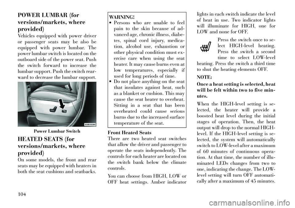
power lumbar switch is located on the
outboard side of the power seat. Push
the switch forward to increase the
lumbar support. Push the switch rear-
ward to decrease the lumbar support.
HEATED SEATS (for
versions/markets, where
provided)
On some models, the front and rear
seats may be equipped with heaters in
both the seat cushions and seatbacks.
WARNING!
Persons who are unable to feel pain to the skin because of ad-
vanced age, chronic illness, diabe-
tes, spinal cord injury, medica-
tion, alcohol use, exhaustion or
other physical condition must ex-
ercise care when using the seat
heater. It may cause burns even at
low temperatures, especially if
used for long periods of time.
Do not place anything on the seat
that insulates against heat, such
as a blanket or cushion. This may
cause the seat heater to overheat.
Sitting in a seat that has been
overheated could cause serious
burns due to the increased surface
temperature of the seat.
Front Heated Seats
There are two heated seat switches
that allow the driver and passenger to
operate the seats independently. The
controls for each heater are located on
the switch bank below the climate
controls.
You can choose from HIGH, LOW or
OFF heat settings. Amber indicator lights in each switch indicate the level
of heat in use. Two indicator lights
will illuminate for HIGH, one for
LOW and none for OFF.
Press the switch once to se-
lect HIGH-level heating.
Press the switch a second
time to select LOW-level
heating. Press the switch a third time
to shut the heating elements OFF.
NOTE:
Once a heat setting is selected, heat
will be felt within two to five min-
utes.
When the HIGH-level setting is se-
lected, the heater will provide a
boosted heat level during the initial
stages of operation. Then, the heat
output will drop to the normal HIGH-
level. If the HIGH-level setting is se-
lected, the system will automatically
switch to LOW-level after a maximum
of 60 minutes of continuous opera-
tion. At that time, the number of illu-
minated LEDs changes from two to
one, indicating the change. The LOW-
level setting will turn OFF automati-
cally after a maximum of 45 minutes.
Power Lumbar Switch
104
Page 149 of 344

CAUTION!(Continued)
After the use of high power draw
accessories, or long periods of the
vehicle not being started (with ac-
cessories still plugged in), the ve-
hicle must be driven a sufficient
length of time to allow the alter-
nator to recharge the vehicle's
battery.
Power outlets are designed for ac-
cessory plugs only. Do not hang
any type of accessory or accessory
bracket from the plug. Improper
use of the power outlet can cause
damage.
SMOKERS PACKAGE KIT
(for versions/markets,
where provided)
With the optional authorized dealer-
installed Smokers Package Kit, a re-
movable ash receiver is inserted into
one of the two cupholders in the cen-
ter front instrument panel. To install
the ash receiver, align the receiver so
the thumb grip on the lid is facing
rearward. Press the ash receiver into
either of the cup wells to secure. Pull upward on the ash receiver to remove
for cleaning and/or storage.
The left rear trim panel cupholder is
designed to accommodate a second
ash receiver, if desired.
POWER INVERTER (for
versions/markets, where
provided)
A 110 Volt, 150 Watt inverter outlet
(for versions/markets, where pro-
vided) converts DC current to AC cur-
rent, and is located on the left rear
trim panel immediately behind the
second row left passenger seat.
The power inverter switch is located
on the instrument panel below the
climate controls.
To turn on the power outlet, press the
switch once. Press the switch a second
time to turn the power outlet off.
This outlet can power cellular phones,
electronics and other low power de-
vices requiring power up to 150
Watts. Certain high-end video games,
such as Playstation3 and XBox360
will exceed this power limit, as will
most power tools.
The power inverter is designed with
built-in overload protection. If the
power rating of 150 Watts is ex-
ceeded, the power inverter will auto-
matically shut down. Once the electri-
cal device has been removed from the
outlet the inverter should automati-
cally reset. If the power rating exceeds
approximately 170 Watts, the power
inverter may have to be reset manu-
ally. To reset the inverter manually
press the power inverter button OFF
and ON. To avoid overloading the cir-
cuit, check the power ratings on elec-
trical devices prior to using the in-
verter.
Power Inverter Outlet
143
Page 158 of 344

CARGO AREA FEATURES
RECHARGEABLE
FLASHLIGHT (for
versions/markets, where
provided)
The rechargeable flashlight is
mounted on the right side of the cargo
area. The flashlight snaps out of the
bezel when needed. The flashlight
features two bright LED light bulbs
and is powered by a lithium battery
that recharges when snapped back
into place and the vehicle is either
running or the key is in the accessory
position.
Press in on the flashlight to release it.To operate the flashlight, press the
switch once for high, twice for low,
and a third time to return to off.
REAR WINDOW
FEATURES
REAR WINDOW
DEFROSTER
The rear window defroster
button is located on the climate
control (Mode) knob. Press
this button to turn on the rear window
defroster and the heated outside mir-
rors (for versions/markets, where
provided). An indicator in the button
will illuminate when the rear window
defroster is on. The rear window de-
froster automatically turns off after
approximately 10 minutes. For an ad- ditional five minutes of operation,
press the button a second time.
NOTE:
You can turn off the heated mir-
ror feature at anytime by press-
ing the rear window defroster
switch a second time.
To prevent excessive battery drain, use the rear window de-
froster only when the engine is
operating.
CAUTION!
Failure to follow these cautions can
cause damage to the heating ele-
ments:
Use care when washing the insideof the rear window. Do not use
abrasive window cleaners on the
interior surface of the window.
Use a soft cloth and a mild wash-
ing solution, wiping parallel to the
heating elements. Labels can be
peeled off after soaking with
warm water.
(Continued)
Press And Release
Three-Press Switch
152
Page 166 of 344

CD Player . . . . . . . . . . . . . . . . . . . . . . . . . . . 208
CD/DVD DISC MAINTENANCE . . . . . . . . . . . . . 208
RADIO OPERATION AND MOBILE PHONES . . . 208
CLIMATE CONTROLS . . . . . . . . . . . . . . . . . . . . 209 MANUAL HEATING AND AIRCONDITIONING SYSTEM (for
versions/markets, where provided) . . . . . . . . 209
REAR MANUAL CLIMATE CONTROL (for versions/markets, where provided) . . . . . . . . 212
AUTOMATIC TEMPERATURE CONTROL (ATC) (for versions/markets, where
provided) . . . . . . . . . . . . . . . . . . . . . . . . . . . . 213
SUMMER OPERATION . . . . . . . . . . . . . . . . . 220
WINTER OPERATION . . . . . . . . . . . . . . . . . . 220
VACATION/STORAGE . . . . . . . . . . . . . . . . . . 220
WINDOW FOGGING . . . . . . . . . . . . . . . . . . . 220
OUTSIDE AIR INTAKE . . . . . . . . . . . . . . . . . 220
OPERATING TIPS . . . . . . . . . . . . . . . . . . . . . 220
A/C AIR FILTER . . . . . . . . . . . . . . . . . . . . . . 220
160
Page 167 of 344

INSTRUMENT PANEL FEATURES1 — Air Vents5 — Analog Clock9 — DVD (for versions/
markets, where provided) 13 — Ignition Switch
2 — Instrument Cluster 6 — Upper Glove
Compartment10 — Storage Bin
14 — Hood Release
3 — Shift Lever 7 — Lower Glove
Compartment11 — Cup Holders
15 — Dimmer Switch
4 — Radio 8 — Climate Controls 12 — Switch Bank 16 — Headlight Switch
161
Page 215 of 344
CLIMATE CONTROLS
The Climate Control system allows
you to regulate the temperature,
amount, and direction of air circulat-
ing throughout the vehicle. The con-
trols are located on the instrument
panel, below the radio.
MANUAL HEATING AND
AIR CONDITIONING
SYSTEM (for versions/
markets, where provided)
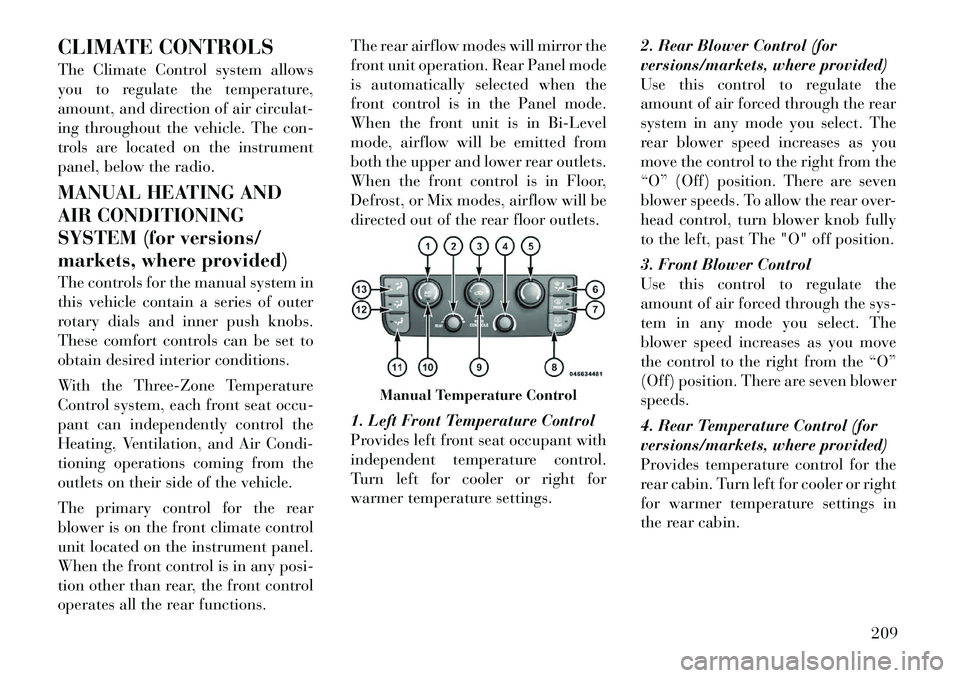
The controls for the manual system in
this vehicle contain a series of outer
rotary dials and inner push knobs.
These comfort controls can be set to
obtain desired interior conditions.
With the Three-Zone Temperature
Control system, each front seat occu-
pant can independently control the
Heating, Ventilation, and Air Condi-
tioning operations coming from the
outlets on their side of the vehicle.
The primary control for the rear
blower is on the front climate control
unit located on the instrument panel.
When the front control is in any posi-
tion other than rear, the front control
operates all the rear functions.The rear airflow modes will mirror the
front unit operation. Rear Panel mode
is automatically selected when the
front control is in the Panel mode.
When the front unit is in Bi-Level
mode, airflow will be emitted from
both the upper and lower rear outlets.
When the front control is in Floor,
Defrost, or Mix modes, airflow will be
directed out of the rear floor outlets.
1. Left Front Temperature Control
Provides left front seat occupant with
independent temperature control.
Turn left for cooler or right for
warmer temperature settings.
2. Rear Blower Control (for
versions/markets, where provided)
Use this control to regulate the
amount of air forced through the rear
system in any mode you select. The
rear blower speed increases as you
move the control to the right from the
“O” (Off) position. There are seven
blower speeds. To allow the rear over-
head control, turn blower knob fully
to the left, past The "O" off position.
3. Front Blower Control
Use this control to regulate the
amount of air forced through the sys-
tem in any mode you select. The
blower speed increases as you move
the control to the right from the “O”
(Off) position. There are seven blower
speeds.
4. Rear Temperature Control (for
versions/markets, where provided)
Provides temperature control for the
rear cabin. Turn left for cooler or right
for warmer temperature settings in
the rear cabin.
Manual Temperature Control
209
Page 218 of 344

13. Panel Mode ButtonAir is directed through the outlets
in the instrument panel. These
outlets can be adjusted for direc-
tion, and turned on or off to control
airflow.
NOTE:
For maximum airflow to the rear,
the center instrument panel out-
lets can be directed toward the
rear seat passengers.
Economy Mode
If ECONOMY mode is desired, press
the A/C button to turn off the indica-
tor light and the A/C compressor. Ro-
tate the temperature control knob to
the desired temperature.
Max A/C
For maximum cooling use the A/C
and Recirculation mode buttons at
the same time.
REAR MANUAL CLIMATE
CONTROL (for
versions/markets, where
provided)
The Rear Manual Climate Control
system has floor air outlets at the rear of the right side sliding door, and
overhead outlets at each outboard
rear seating position. The unit pro-
vides warm or cool air through the
floor and upper outlets.
The rear blower and temperature con-
trols for the rear seat passengers are
located in the headliner, near the cen-
ter of the vehicle.
Rear Blower Control
The primary control for the rear
blower is on the front climate control
unit, located on the instrument panel.
Only when the front control for the
rear blower is in the
REARposition do the second row seat occupants
have control of the rear blower speed.
The rear blower control, located in the
rear overhead console, has an off po-
sition and a range of blower speeds.
This allows the second row seat occu-
pants to control the volume of air
circulated in the rear of the vehicle.
CAUTION!
Interior air enters the Rear Manual
Climate Control system through an
intake grille, located in the right side
trim panel behind the third row
seats. The heater outlets are located
in the right side trim panel, just be-
hind the sliding door. Do not block
or place objects directly in front of
the inlet grille or heater outlets. The
electrical system could overload,
causing damage to the blower motor.
Rear Temperature Control
The rear mode selection REAR,al-
lows the settings to be controlled by
the rear mode control knob.
To change the temperature in the rear
of the vehicle, rotate the temperature
Rear Manual Climate Controls
1 – Rear Blower 3 – Rear Mode
2 – Rear Tem-
perature 4 – Rear Climate
Control Lock
212
Page 220 of 344
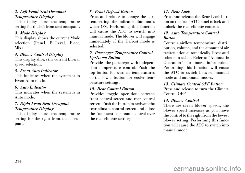
2. Left Front Seat Occupant
Temperature Display
This display shows the temperature
setting for the left front seat occupant.
3. Mode Display
This display shows the current Mode
selection (Panel, Bi-Level, Floor,
Mix).
4. Blower Control Display
This display shows the current Blower
speed selection.
5. Front Auto Indicator
This indicates when the system is in
Front Auto mode.
6. Auto Indicator
This indicates when the system is in
Auto mode.
7. Right Front Seat Occupant
Temperature Display
This display shows the temperature
setting for the right front seat occu-
pant.8. Front Defrost Button
Press and release to change the cur-
rent setting, the indicator illuminates
when ON. Performing this function
will cause the ATC to switch into
manual mode. The blower will engage
immediately if the Defrost mode is
selected.
9. Passenger Temperature Control
Up/Down Button
Provides the passenger with indepen-
dent temperature control. Push the
top button for warmer temperatures
or the lower button for cooler tem-
perature settings.
10. Rear Control Button
Provides toggle operation between
front control screen and rear control
screen. Push the button to activate the
rear climate control screen and allow
the front seat occupants control over
the rear climate settings.
11. Rear Lock
Press and release the Rear Lock but-
ton on the front ATC panel to lock and
unlock the rear climate controls
12. Auto Temperature Control
Button
Controls airflow temperature, distri-
bution, volume, and the amount of air
recirculation automatically. Press and
release to select. Refer to “Automatic
Operation” for more information.
Performing this function will cause
the ATC to switch between manual
mode and automatic modes.
13. Climate Control OFF Button
Press and release to turn the Climate
Control OFF.
14. Blower Control
There are seven blower speeds, the
blower speed increases as you move
the control to the right from the lowest
blower setting. Performing this func-
tion will cause the ATC to switch into
manual mode.
214