engine Lancia Voyager 2014 Owner handbook (in English)
[x] Cancel search | Manufacturer: LANCIA, Model Year: 2014, Model line: Voyager, Model: Lancia Voyager 2014Pages: 364, PDF Size: 3.49 MB
Page 227 of 364
3. When the system is set up for your
comfort level, it is not necessary to
change the settings. You will experi-
ence the greatest efficiency by simply
allowing the system to function auto-
matically.
NOTE:
It is not necessary to move thetemperature settings for cold or
hot vehicles. The system auto-
matically adjusts the tempera-
ture, mode and fan speed to pro-
vide comfort as quickly as
possible.
The temperature can be dis- played in English or Metric units
by selecting the “Display Units
of Measure in” customer-
programmable feature. Refer to
the “Electronic Vehicle Informa-
tion Center (EVIC) — Customer-
Programmable Features” in this
Section.
To provide you with maximum com-
fort in the automatic mode, during
cold start-ups, the blower fan will re-
main on low until the engine warms
up. The fan will engage immediately if the Defrost mode is selected, or by
changing the front blower knob set-
ting.
Manual Operation Override
This system offers a full complement
of manual override features. The
AUTO symbol in the front ATC dis-
play will be turned off when the sys-
tem is being used in the manual mode.
NOTE: If not operating in AUTO
mode, the system will not auto-
matically sense the presence of fog,
mist or ice on the windshield. DE-
FROST mode must be manually
selected to clear the windshield
and side glass.
Air Conditioning (A/C)
The Air Conditioning (A/C) button
allows the operator to manually acti-
vate or deactivate the air conditioning
system. When in A/C mode and the
ATC is set to a cool temperature, de-
humidified air flows through the air
outlets. If Economy mode is desired,
press the A/C button to turn off the
A/C mode in the ATC display and
deactivate the A/C system.
NOTE:
If the system is in Mix, Floor or
Defrost Mode, the A/C can be
turned off, but the A/C system
shall remain active to prevent
fogging of the windows.
If fog or mist appears on the windshield or side glass, select
Defrost mode and increase
blower speed.
Recirculation Control
When outside air contains
smoke, odors, or high hu-
midity, or if rapid cooling is
desired, you may wish to
recirculate interior air by pressing the
Recirculation control button. Recir-
culation mode should only be used
temporarily. A LED will illuminate on
the Recirculation control button when
Recirculation mode is selected. Push
the button a second time to turn off
the Recirculation mode LED and al-
low outside air into the vehicle.
221
Page 230 of 364
CAUTION!
Interior air enters the Rear Auto-
matic Temperature Control System
through an intake grille, located in
the right side trim panel behind the
third row seats. The rear outlets are
located in the right side trim panel
of the 3rd Row seat. Do not block or
place objects directly in front of the
inlet grille or heater outlets. The
electrical system could overload
causing damage to the blower mo-
tor.
Rear Temperature Control
To change the temperature in the rear
of the vehicle, rotate the temperature
knob counterclockwise to lower the
temperature, and clockwise to in-
crease the temperature. The rear tem-
perature settings are displayed in the
front ATC panel.
When rear controls are locked by the
front system, the Rear Temperature
Lock symbol on the temperature
knob is illuminated and any rear over-
head adjustments are ignored. Rear Mode Control
Auto Mode
The rear system automatically main-
tains the correct mode and comfort
level desired by the rear seat occu-
pants.
Headliner Mode
Air comes from the outlets in
the headliner. Each of these
outlets can be individually adjusted to
direct the flow of air. Moving the air
vanes of the outlets to one side will
shut off the airflow.
Bi-Level Mode
Air comes from both the head-
liner outlets and the floor out-
lets.
NOTE: In many temperature po-
sitions, the Bi-Level mode is de-
signed to provide cooler air out of
the headliner outlets and warmer
air from the floor outlets.
Floor Mode Air comes from the floor out-
lets. Recirculation Control
When outside air contains
smoke, odors, or high hu-
midity, or if rapid cooling is
desired, you may wish to
recirculate interior air by pressing the
Recirculation control button. Recir-
culation mode should only be used
temporarily. The recirculation LED
will illuminate when this button is
selected. Push the button a second
time to turn off the Recirculation
mode LED and allow outside air into
the vehicle.
NOTE: In cold weather, use of the
Recirculation mode may lead to
excessive window fogging. The Re-
circulation mode is not allowed in
Defrost mode to improve window
clearing operation. Recirculation
will be disabled automatically if
this mode is selected.
SUMMER OPERATION
The engine cooling system in air con-
ditioned vehicles must be protected
with a high-quality antifreeze coolant
to provide proper corrosion protection
224
Page 231 of 364
and to protect against engine over-
heating. A solution of 50% ethylene
glycol antifreeze coolant and 50%
water is recommended. Refer to
“Maintenance Procedures” in “Main-
taining Your Vehicle” for proper cool-
ant selection.
WINTER OPERATION
To ensure the best possible heater and
defroster performance, make sure the
engine cooling system is functioning
properly and the proper amount,
type, and concentration of coolant is
used. Refer to “Maintenance Proce-
dures” in “Maintaining Your Vehicle”
for proper coolant selection. Use of
the air Recirculation mode during
Winter months is not recommended,
because it may cause window fogging.
VACATION/STORAGE
Before you store your vehicle, or keep
it out of service (i.e., vacation) for two
weeks or more, run the air condition-
ing system at idle for about five min-
utes, in fresh air with the blower set-
ting on high. This will ensureadequate system lubrication to mini-
mize the possibility of compressor
damage when the system is started
again.
WINDOW FOGGING
Vehicle windows tend to fog on the
inside in mild, rainy and/or humid
weather. To clear the windows, select
Defrost or Mix mode and increase the
front blower speed. Do not use the
Recirculation mode without A/C for
long periods, as fogging may occur.
OUTSIDE AIR INTAKE
Make sure the air intake, located di-
rectly in front of the windshield, is
free of obstructions such as leaves.
Leaves collected in the air intake may
reduce airflow, and if they enter the
plenum they could plug the water
drains. In Winter months make sure
the air intake is clear of ice, slush and
snow.
A/C AIR FILTER
On vehicles equipped with Automatic
Temperature Control (ATC), the cli-
mate control system filters out dustand pollen from the air. Refer to “Air
Conditioning” in “Maintaining Your
Vehicle” for filter replacement in-
structions.
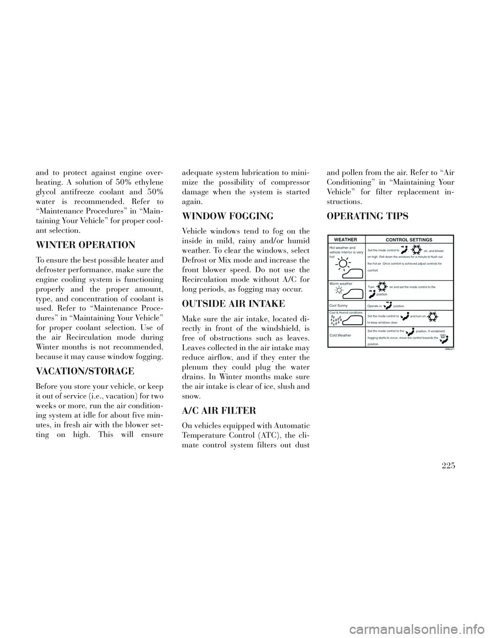
OPERATING TIPS
225
Page 233 of 364
5
STARTING AND OPERATING
STARTING PROCEDURES..................231
AUTOMATIC TRANSMISSION .............231
KEYLESS ENTER-N-GO™ (for versions/markets, where provided) ...................... .232
NORMAL STARTING — GASOLINE ENGINE . .232
EXTREME COLD WEATHER (BELOW �29°C). .233
IF ENGINE FAILS TO START ..............233
AFTER STARTING ..................... .234
NORMAL STARTING – DIESEL ENGINE .....234
AUTOMATIC TRANSMISSION ...............236
KEY IGNITION PARK INTERLOCK .........237
BRAKE/TRANSMISSION SHIFT INTERLOCK SYSTEM ............................ .237
SIX-SPEED AUTOMATIC TRANSMISSION . . .237
DRIVING ON SLIPPERY SURFACES ..........242
ACCELERATION ....................... .242
TRACTION ........................... .242
DRIVING THROUGH WATER ...............243
FLOWING/RISING WATER ................243
SHALLOW STANDING WATER .............243
POWER STEERING ...................... .244
POWER STEERING FLUID CHECK .........245
227
Page 235 of 364
Tire Spinning........................ .263
Tread Wear Indicators ...................264
Life Of Tire .......................... .264
Replacement Tires ..................... .264
TIRE CHAINS (TRACTION DEVICES) .........265
TIRE ROTATION RECOMMENDATIONS .......266
TIRE PRESSURE MONITOR SYSTEM (TPMS) . .266 BASE SYSTEM ........................ .268
PREMIUM SYSTEM (for versions/markets, where provided) ............................ .270
FUEL REQUIREMENTS — GASOLINE ENGINE . . .272
METHANOL ......................... .273
ETHANOL ........................... .273
CLEAN AIR GASOLINE ..................274
MMT IN GASOLINE .................... .274
MATERIALS ADDED TO FUEL ............274
FUEL REQUIREMENTS — DIESEL ENGINE . . . .275
BIODIESEL FUEL REQUIREMENTS ..........275
ADDING FUEL ......................... .275
LOCKING FUEL FILLER CAP (GAS CAP) (for versions/markets, where provided) .........275
TRAILER TOWING ...................... .276
COMMON TOWING DEFINITIONS ..........276
BREAKAWAY CABLE ATTACHMENT ........277
TOWING TIPS ........................ .282
229
Page 237 of 364
STARTING
PROCEDURES
Before starting your vehicle, adjust
your seat, adjust the inside and out-
side mirrors, fasten your seat belt, and
if present, instruct all other occupants
to buckle their seat belts.
WARNING!
Never leave children alone in avehicle, or with access to an un-
locked vehicle. Allowing children
to be in a vehicle unattended is
dangerous for a number of rea-
sons. A child or others could be
seriously or fatally injured. Chil-
dren should be warned not to
touch the parking brake, brake
pedal or the shift lever.
(Continued)
WARNING!(Continued)
Do not leave the key fob in or nearthe vehicle, or in a location acces-
sible to children, and do not leave
the ignition of a vehicle equipped
with Keyless Enter-N-Go™ in the
ACC or ON/RUN mode. A child
could operate power windows,
other controls, or move the ve-
hicle.
AUTOMATIC
TRANSMISSION
The shift lever must be in the NEU-
TRAL or PARK position before you
can start the engine. Apply the brakes
before shifting into any driving gear.
CAUTION!
Damage to the transmission may
occur if the following precautions
are not observed:
Do not shift from REVERSE,PARK, or NEUTRAL into any
forward gear when the engine is
above idle speed.
(Continued)
CAUTION!(Continued)
Shift into PARK only after thevehicle has come to a complete
stop.
Shift into or out of REVERSE only after the vehicle has come to
a complete stop and the engine is
at idle speed.
Before shifting into any gear, make sure your foot is firmly on
the brake pedal.
Using Fob With Integrated Key
(Tip Start)
NOTE: Normal starting of either a
cold or a warm engine is obtained
without pumping or pressing the
accelerator pedal.
Do not press the accelerator. Use the
Fob with Integrated Key to briefly
turn the ignition switch to the START
position and release it as soon as the
starter engages. The starter motor will
continue to run, and it will disengage
automatically when the engine is run-
ning. If the engine fails to start, the
starter will disengage automatically in
10 seconds. If this occurs, turn the
231
Page 238 of 364
ignition switch to the LOCK position,
wait 10 to 15 seconds, then repeat the
“Normal Starting” procedure.
KEYLESS ENTER-N-GO™
(for versions/markets,
where provided)
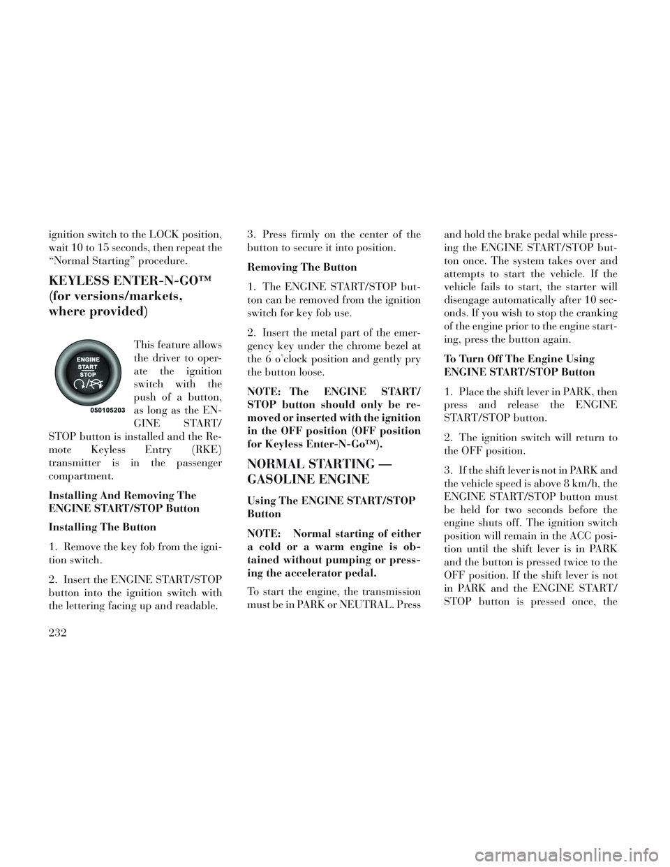
This feature allows
the driver to oper-
ate the ignition
switch with the
push of a button,
as long as the EN-
GINE START/
STOP button is installed and the Re-
mote Keyless Entry (RKE)
transmitter is in the passenger
compartment.
Installing And Removing The
ENGINE START/STOP Button
Installing The Button
1. Remove the key fob from the igni-
tion switch.
2. Insert the ENGINE START/STOP
button into the ignition switch with
the lettering facing up and readable. 3. Press firmly on the center of the
button to secure it into position.
Removing The Button
1. The ENGINE START/STOP but-
ton can be removed from the ignition
switch for key fob use.
2. Insert the metal part of the emer-
gency key under the chrome bezel at
the 6 o’clock position and gently pry
the button loose.
NOTE: The ENGINE START/
STOP button should only be re-
moved or inserted with the ignition
in the OFF position (OFF position
for Keyless Enter-N-Go™).
NORMAL STARTING —
GASOLINE ENGINE
Using The ENGINE START/STOP
Button
NOTE: Normal starting of either
a cold or a warm engine is ob-
tained without pumping or press-
ing the accelerator pedal.
To start the engine, the transmission
must be in PARK or NEUTRAL. Press
and hold the brake pedal while press-
ing the ENGINE START/STOP but-
ton once. The system takes over and
attempts to start the vehicle. If the
vehicle fails to start, the starter will
disengage automatically after 10 sec-
onds. If you wish to stop the cranking
of the engine prior to the engine start-
ing, press the button again.
To Turn Off The Engine Using
ENGINE START/STOP Button
1. Place the shift lever in PARK, then
press and release the ENGINE
START/STOP button.
2. The ignition switch will return to
the OFF position.
3. If the shift lever is not in PARK and
the vehicle speed is above 8 km/h, the
ENGINE START/STOP button must
be held for two seconds before the
engine shuts off. The ignition switch
position will remain in the ACC posi-
tion until the shift lever is in PARK
and the button is pressed twice to the
OFF position. If the shift lever is not
in PARK and the ENGINE START/
STOP button is pressed once, the
232
Page 239 of 364
EVIC will display a “Vehicle Not In
Park” message and the engine will
remain running. Never leave a vehicle
out of the PARK position, or it could
roll.
NOTE: If the ignition switch is left
in the ACC or RUN (engine not run-
ning) position and the transmis-
sion is in PARK, the system will
automatically time out after 30
minutes of inactivity and the igni-
tion will switch to the OFF posi-
tion.
Keyless Enter-N-Go™ Functions –
With Driver’s Foot OFF The
Brake Pedal (In PARK Or
NEUTRAL Position)
The Keyless Enter-N-Go™ feature
operates similar to an ignition switch.
It has four positions, OFF, ACC, RUN
and START. To change the ignition
switch positions without starting the
vehicle and use the accessories follow
these steps. Starting with the ignition switch in
the OFF position:
Press the ENGINE START/STOP button once to change the ignition
switch to the ACC position (EVIC
displays “IGNITION MODE
ACCESSORY”),
Press the ENGINE START/STOP button a second time to change the
ignition switch to the RUN position
(EVIC displays “IGNITION MODE
RUN”),
Press the ENGINE START/STOP button a third time to return the
ignition switch to the OFF position
(EVIC displays “IGNITION MODE
OFF”).
EXTREME COLD
WEATHER (BELOW �29°C)
To ensure reliable starting at these
temperatures, use of an externally
powered electric engine block heater
is recommended.
IF ENGINE FAILS TO
START
WARNING!
Never pour fuel or other flam-mable liquids into the throttle
body air inlet opening in an at-
tempt to start the vehicle. This
could result in a flash fire causing
serious personal injury.
Do not attempt to push or tow your vehicle to get it started. Ve-
hicles equipped with an auto-
matic transmission cannot be
started this way. Unburned fuel
could enter the catalytic con-
verter and once the engine has
started, ignite and damage the
converter and vehicle.
(Continued)
233
Page 240 of 364
WARNING!(Continued)
If the vehicle has a dischargedbattery, booster cables may be
used to obtain a start from a
booster battery or the battery in
another vehicle. This type of start
can be dangerous if done improp-
erly. Refer to “Jump Starting” in
“What To Do In Emergencies” for
further information.
Clearing A Flooded Engine (Using
ENGINE START/STOP Button)
If the engine fails to start after you
have followed the “Normal Starting”
or “Extreme Cold Weather" proce-
dures, it may be flooded. To clear any
excess fuel:
1. Press and hold the brake pedal.
2. Press the accelerator pedal all the
way to the floor and hold it.
3. Press and release the ENGINE
START/STOP button once.
The starter motor will engage auto-
matically, run for 10 seconds, and then
disengage. Once this occurs, release the accelerator pedal and the brake pedal,
wait 10 to 15 seconds, then repeat the
“Normal Starting” procedure.
Clearing A Flooded Engine (Using
Fob With Integrated Key)
If the engine fails to start after you
have followed the “Normal Starting”
or “Extreme Cold Weather” proce-
dures, it may be flooded. To clear any
excess fuel:
1. Press the accelerator pedal all the
way to the floor and hold it.
2. place the ignition in the START
position and release it as soon as the
starter engages.
The starter motor will disengage auto-
matically in 10 seconds. Once this oc-
curs, release the accelerator pedal, turn
the ignition switch to the LOCK posi-
tion, wait 10 to 15 seconds, then repeat
the “Normal Starting” procedure.
CAUTION!
To prevent damage to the starter,
wait 10 to 15 seconds before trying
again.
AFTER STARTING
The idle speed is controlled automati-
cally and it will decrease as the engine
warms up.
NORMAL STARTING –
DIESEL ENGINE
1. Turn the ignition switch to the ON
position.
2. Watch for the “Wait To Start
Light” in the instrument cluster. Refer
to “Instrument Cluster” in “Under-
standing Your Instrument Panel” for
further information. It will illuminate
for two to ten seconds or more, de-
pending on engine temperature.
When the “Wait To Start Light” goes
out, the engine is ready to start.
3. DO NOT press the accelerator.
Turn the ignition switch to the START
position and release when the engine
starts.
234
Page 241 of 364

CAUTION!
To prevent damage to the starter,
DO NOT crank the engine for more
than 15 second intervals at one
time. Wait 10 to 15 seconds before
trying again.
4. After the engine starts, allow it to
idle for approximately 30 seconds be-
fore driving. This allows oil to circu-
late and lubricate the turbocharger. Starting And Operating Cautions
– Diesel Engine
WARNING!
NEVER pour fuel or other flam-
mable liquid into the air inlet open-
ing in an attempt to start the ve-
hicle. This could result in a flash
fire causing serious personal injury.
Running a cold engine at high speeds during driving or idling may
damage engine components.
Before turning off your turbo diesel engine, always allow the engine to
return to normal idle speed and run
for several seconds. This assures proper lubrication of the turbo-
charger. This is particularly neces-
sary after any period of hard driv-
ing.
Turbocharger Cool Down
NOTE: Letting the engine idle af-
ter extended operation allows the
turbine housing to cool to normal
operating temperature.
The following chart should be used as
a guide in determining the amount of
engine idle time required to suffi-
ciently cool down the turbocharger
before shut down, depending upon
the type of driving and the amount of
cargo.
Turbocharger "Cool Down" Chart
Driving
Conditions
Load Turbocharger
Temperature
Idle Time (in minutes)
Before Shut Down
Stop & Go EmptyCoolLess than 1
Stop & Go MediumWarm 1
Highway Speeds MediumWarm 2
City Traffic Max. GCWR Warm3
Highway Speeds Max. GCWR Warm4
Uphill Grade Max. GCWR Hot5
235