engine Lancia Voyager 2014 Owner handbook (in English)
[x] Cancel search | Manufacturer: LANCIA, Model Year: 2014, Model line: Voyager, Model: Lancia Voyager 2014Pages: 364, PDF Size: 3.49 MB
Page 77 of 364
PERIODIC SAFETY
CHECKS YOU SHOULD
MAKE OUTSIDE THE
VEHICLE
Tires
Examine tires for excessive tread wear
and uneven wear patterns. Check for
stones, nails, glass, or other objects
lodged in the tread or sidewall. In-
spect the tread for cuts and cracks.
Inspect sidewalls for cuts, cracks and
bulges. Check the wheel nuts for
tightness. Check the tires (including
spare) for proper cold inflation pres-
sure.
Lights
Have someone observe the operation
of brake lights and exterior lights
while you work the controls. Check
turn signal and high beam indicator
lights on the instrument panel.Door Latches
Check for positive closing, latching,
and locking.
Fluid Leaks
Check area under vehicle after over-
night parking for fuel, engine coolant,
oil, or other fluid leaks. Also, if gaso-
line fumes are detected or if fuel,
power steering fluid (if equipped), or
brake fluid leaks are suspected, the
cause should be located and corrected
immediately.
71
Page 107 of 364
Press thebutton and say the
“Voice Training”, “System Train-
ing”, “Start Voice Training”
command.
Repeat the words and phrases when
prompted by the Uconnect® Phone.
For best results, the Voice Training
session should be completed when the
vehicle is parked with the engine run-
ning, all windows closed, and the
blower fan switched OFF.
This procedure may be repeated with
a new user. The system will adapt to
the last trained voice only.
To restore the Voice Command system
to factory default settings, enter the
Voice Training session via the above
procedure and follow the prompts.
RESET
Press thebutton.
After the “Ready” prompt, and the following beep, say “Setup,” then
“Reset.”
This will delete all phone pairing,
phone book entries, and other settings in all language modes. The System
will prompt you before resetting to
factory settings.
VOICE COMMAND
For best performance, adjust the
rearview mirror to provide at least 1
cm gap between the overhead con-
sole (for versions/markets, where
provided) and the mirror.
Always wait for the beep before speaking.
Speak normally without pausing, just as you would speak to a person
sitting a few meters away from you.
Make sure that no one other than you is speaking during a Voice
Command period.
Performance is maximized under:
low-to-medium blower setting,
low-to-medium vehicle speed,
low road noise,
smooth road surface,
fully closed windows, dry weather condition.
Even though the system is designed
for users speaking in European
English, Dutch, French, German,
Italian, or Spanish accents, the sys-
tem may not always work for some.
When navigating through an auto- mated system such as voice mail, or
when sending a page, at the end of
speaking the digit string, make sure
to say “Send.”
Storing names in the phonebook when the vehicle is not in motion is
recommended.
It is not recommended to store simi- lar sounding names in the
Uconnect® Phonebook.
Phonebook (Downloaded and Uconnect® Phone Local) name
recognition rate is optimized when
the entries are not similar.
Numbers must be spoken in single digits. “800” must be spoken
“eight-zero-zero” not “eight
hundred.”
101
Page 117 of 364

once you are in that menu then say
“Voice Training.” This will train your
own voice to the system and will im-
prove recognition.
2. Repeat the words and phrases
when prompted by Uconnect® Voice.
For best results, the Voice Training
session should be completed when the
vehicle is parked, engine running, all
windows closed, and the blower fan
switched off. This procedure may be
repeated with a new user. The system
will adapt to the last trained voice
only.
SEATS
Seats are a part of the Occupant Re-
straint System of the vehicle.
WARNING!
It is dangerous to ride in a cargoarea, inside or outside of a ve-
hicle. In a collision, people riding
in these areas are more likely to
be seriously injured or killed.
(Continued)
WARNING!(Continued)
Do not allow people to ride in anyarea of your vehicle that is not
equipped with seats and seat
belts. In a collision, people riding
in these areas are more likely to
be seriously injured or killed.
Be sure everyone in your vehicle is in a seat and using a seat belt
properly.
POWER SEATS (for
versions/markets, where
provided)
Some models may be equipped with
eight-way power seats for the driver
and front passenger. The power seat
switches are located on the outboard
side of the seat. The switches control
the movement of the seat cushion and
the seatback.
WARNING!
Adjusting a seat while drivingmay be dangerous. Moving a seat
while driving could result in loss
of control which could cause a
collision and serious injury or
death.
Seats should be adjusted before fastening the seat belts and while
the vehicle is parked. Serious in-
jury or death could result from a
poorly adjusted seat belt.
(Continued)
Driver Power Seat Switch
1 — Seat Switch 2 — Seatback Switch
111
Page 135 of 364

INTERIOR LIGHTING
Interior lights are turned on when a
door or liftgate is opened, the Remote
Keyless Entry (RKE) transmitter is
activated, or when the dimmer con-
trol is moved to the extreme top.
The interior lights will automatically
turn off in approximately 10 minutes
for the first activation and 90 seconds
every activation thereafter until the
engine is started, if one of the follow-
ing occur:
1. A door, sliding door or the liftgate
is left open
2. Any overhead reading light is left
on
NOTE: The key must be out of the
ignition switch or the ignition
switch must be in the OFF position
for this feature to operate.
Halo Lights (for versions/markets,
where provided)
Halo lights are strategically placed
soft lighting that help to illuminatespecific areas to aid the occupants in
locating specific features while driv-
ing at night.
The Halo control switch is located to
the right of the dimmer switch.
To activate the Halo lights,
rotate the Halo switch con-
trol upward or downward
to increase or decrease the
lighting.
PARKING LIGHTS
Turn the headlight switch
knob to the first detent to turn
the parking lights on. This also turns
on all instrument panel lighting.
HEADLIGHTS
Turn the headlight switch
knob to the second detent to
turn the headlights and
parking lights on. This also
turns on all instrument panel lighting.
To change the brightness of the in-
strument panel lights, rotate the dim-
mer control up or down.
AUTOMATIC HEADLIGHTS
(for versions/markets,
where provided)
This system automatically turns your
headlights on or off based on ambient
light levels. To turn the system on,
turn the headlight switch to the ex-
treme counterclockwise position
aligning the indicator with AUTO on
the headlight switch. When the sys-
tem is on, the Headlight Time Delay
feature is also on. This means your
headlights will stay on for up to 90
seconds after you turn the ignition
switch OFF. To turn the Automatic
System off, turn the headlight switch
clockwise to the O (Off) position.
Halo Control Switch
129
Page 136 of 364

NOTE: The engine must be run-
ning before the headlights will
come on in the Automatic mode.
HEADLIGHTS ON WITH
WIPERS (for versions/
markets, where provided)
When your headlights are in the Au-
tomatic mode and the engine is run-
ning, the headlights will automati-
cally turn on when the wiper system is
also turned on. In addition, the head-
lights will turn off when the wipers are
turned off if they were turned on by
this feature. Headlights on when
windshield wipers are on may be
found on vehicles equipped with an
automatic headlight system. Refer to
“Electronic Vehicle Information Cen-
ter (EVIC)/Customer-Programmable
Features” in “Understanding Your In-
strument Panel” for further informa-
tion.
HEADLIGHT DELAY (for
versions/markets, where
provided)
This feature provides the safety of
headlight illumination for up to
90 seconds after exiting your vehicle.
To activate the delay feature, turn OFF
the ignition switch while the headlights
are still on. Then turn off the head-
lights within 45 seconds. The 90 sec-
ond delay interval begins when head-
light switch is turned off. If the
headlights or parking lights are turned
back on or the ignition switch is turned
ON, the delay will be cancelled.
When exiting the vehicle the driver
can choose to have the headlights re-
main on for 30, 60, or 90 seconds or
not remain on. To change the timer
setting, see your authorized dealer.
The headlight delay time is program-
mable on vehicles equipped with an
EVIC. Refer to “Electronic Vehicle In-
formation Center (EVIC)/Customer-
Programmable Features” in “Under-
standing Your Instrument Panel” for
further information.If the headlights are turned off before
the ignition, they will turn off in the
normal manner.
NOTE: The headlights must be
turned off within 45 seconds of
turning the ignition OFF to activate
this feature.
FRONT AND REAR FOG
LIGHTS (for versions/
markets, where provided)
The front and rear fog light switch is
built into the headlight switch.
The front and rear fog lights
may be operated as desired
when visibility is poor due to
fog. The fog lights will activate in the
following order: Press the headlight
switch once and the front fog lights
Fog Light Switch
130
Page 156 of 364
Each of these outlets can support 160
Watts (13 Amps). Do not exceed 160
Watts (13 Amps) for each of these
outlets.
The power outlets include tethered
caps, labeled with a key or battery
symbol indicating the power source.
The power outlet, located on the lower
instrument panel, is powered directly
from the battery. Items plugged into
this power outlet may discharge the
battery and/or prevent the engine
from starting.WARNING!
To avoid serious injury or death:
Only devices designed for use inthis type of outlet should be in-
serted into any 12 Volt outlet.
Do not touch with wet hands.
Close the lid when not in use and while driving the vehicle.
If this outlet is mishandled, it may cause an electric shock and fail-
ure.
CAUTION!
Many accessories that can beplugged in draw power from the
vehicle's battery, even when not
in use (i.e., cellular phones, etc.).
Eventually, if plugged in long
enough, the vehicle's battery will
discharge sufficiently to degrade
battery life and/or prevent the
engine from starting.
(Continued)
CAUTION!(Continued)
Accessories that draw higherpower (i.e., coolers, vacuum
cleaners, lights, etc.), will de-
grade the battery even more
quickly. Only use these intermit-
tently and with greater caution.
After the use of high power draw accessories, or long periods of the
vehicle not being started (with
accessories still plugged in), the
vehicle must be driven a suffi-
cient length of time to allow the
alternator to recharge the vehi-
cle's battery.
Power outlets are designed for ac- cessory plugs only. Do not hang
any type of accessory or accessory
bracket from the plug. Improper
use of the power outlet can cause
damage.
SMOKERS PACKAGE KIT
With the optional authorized dealer-
installed Smokers Package Kit, a re-
movable ash receiver is inserted into
one of the two cupholders in the cen-
ter front instrument panel. To install
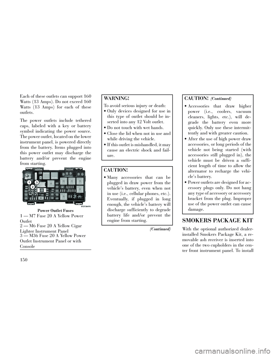
Power Outlet Fuses
1 — M7 Fuse 20 A Yellow Power
Outlet
2 — M6 Fuse 20 A Yellow Cigar
Lighter Instrument Panel
3 — M36 Fuse 20 A Yellow Power
Outlet Instrument Panel or with
Console
150
Page 167 of 364

To prevent excessive batterydrain, use the rear window de-
froster only when the engine is
operating.
CAUTION!
Failure to follow these cautions can
cause damage to the heating ele-
ments:
Use care when washing the insideof the rear window. Do not use
abrasive window cleaners on the
interior surface of the window.
Use a soft cloth and a mild wash-
ing solution, wiping parallel to
the heating elements. Labels can
be peeled off after soaking with
warm water.
Do not use scrapers, sharp instru- ments, or abrasive window clean-
ers on the interior surface of the
window.
Keep all objects a safe distance from the window.
ROOF LUGGAGE RACK
(for versions/markets,
where provided)
The crossbars on your vehicle are de-
livered stowed within the roof rack
side rails. If adding cargo, deploy the
crossbars. Distribute cargo weight
evenly on the roof rack crossbars, to
maximum of 68 kg. The roof rack
does not increase the total load carry-
ing capacity of the vehicle. Be sure the
total load of cargo inside the vehicle
plus that on the external rack does not
exceed the maximum vehicle load ca-
pacity.
The crossbars and side rails are de-
signed to carry weight on vehicles
equipped with a luggage rack. The load must not exceed 68 kg, and
should be uniformly distributed over
the luggage rack crossbars.
NOTE:
Crossbars are error-proofed and
cannot be deployed or stowed in
the incorrect positions.
To help control wind noise, stow the crossbars in the side rails
when they are not in use.
DEPLOYING THE
CROSSBARS
To deploy the crossbars, completely
loosen the thumb screws at both ends
of the crossbar and lift the crossbar
from its stowed position in the side
rail. Repeat with crossbar on the op-
posite side.
Crossbar Stowed In Side Rail
Loosening Crossbars
161
Page 178 of 364
INSTRUMENT CLUSTER
DESCRIPTIONS
1. Tachometer
The red segments indicate the maxi-
mum permissible engine revolutions
per minute (RPM x 1000) for each
gear range. Before reaching the red
area, ease up on the accelerator.
2. Front Fog Light Indicator (for
versions/markets, where provided)This indicator will illumi-
nate when the front fog
lights are on.
3. Park/Headlight ON Indicator
This indicator will illumi-
nate when the park lights or
headlights are turned on.
4. Turn Signal Indicators The arrow will flash with
the exterior turn signal
when the turn signal lever is
operated.
If the vehicle is driven 1.6 km with
either turn signal on, a continuous
chime will sound to alert you to turn the signal off. If either indicator
flashes at a rapid rate, check for a
defective outside light bulb.
5. High Beam Indicator
This indicator shows that the
high beam headlights are on.
Push the multifunction lever forward
to switch the headlights to high beam,
and pull toward yourself (normal po-
sition) to return to low beam.
6. Odometer Display / Electronic
Vehicle Information Center (EVIC)
Display
Odometer Display / Trip Odometer
Display (for versions/markets,
where provided) The odometer dis-
play shows the total distance the ve-
hicle has been driven.
NOTE: Some warnings will be
displayed in the Electronic Vehicle
Information Center Display Area
located in the instrument cluster.
Refer to ”Electronic Vehicle Infor-
mation Center (EVIC) Display”
(for versions/markets, where pro-
vided) for further information. LoW tirE
When the appropriate condition ex-
ists, the odometer display will toggle
between LoW and tirE for three
cycles.
gASCAP
If the vehicle diagnostic system deter-
mines that the fuel filler cap is loose,
improperly installed, or damaged, a
“gASCAP” message will display in the
odometer display area. Tighten the
fuel filler cap properly and press the
STEP button on the steering wheel to
turn off the message. If the problem
continues, the message will appear
the next time the vehicle is started.
noFUSE
If the vehicle diagnostic system deter-
mines that the Ignition Off Draw
(IOD) fuse is improperly installed, or
damaged, a “noFUSE” message will
display in the odometer display area.
For further information on fuses and
fuse locations refer to “Fuses” in
“Maintaining Your Vehicle”.
172
Page 179 of 364
CHAngE OIL
Your vehicle is equipped with an en-
gine oil change indicator system. The
CHAngE OILmessage will flash in
the instrument cluster odometer for
approximately 12 seconds, after a
single chime has sounded, to indicate
the next scheduled oil change inter-
val. The engine oil change indicator
system is duty cycle-based, which
means the engine oil change interval
may fluctuate dependent upon your
personal driving style.
Unless reset, this message will con-
tinue to display each time you turn the
ignition switch to the ON/RUN posi-
tion. To turn off the message tempo-
rarily, press and release the STEP
button on the steering wheel. To reset
the oil change indicator system (after
performing the scheduled mainte-
nance), perform the following steps.
1. Turn the ignition switch to the ON/
RUN position (do not start the en-
gine).
2. Fully depress the accelerator pedal,
slowly, three times within 10 seconds. 3. Turn the ignition switch to the
OFF/LOCK position.
NOTE: If the indicator message
illuminates when you start the en-
gine, the oil change indicator sys-
tem did not reset. If necessary, re-
peat these steps.
Electronic Vehicle Information
Center (EVIC) Display (for versions/
markets, where provided)
The Electronic Vehicle Information
Center (EVIC) features a driver-
interactive display that is located in
the instrument cluster. For further in-
formation, refer to “Electronic Ve-
hicle Information Center (EVIC)”.
7. Anti-Lock Brake (ABS) Light
This light monitors the
Anti-Lock Brake System
(ABS). The light will turn
on when the ignition switch
is turned to the ON/RUN position and
may stay on for as long as four sec-
onds.
If the ABS light remains on or turns on
while driving, it indicates that the Anti-Lock portion of the brake sys-
tem is not functioning and that service
is required. However, the conven-
tional brake system will continue to
operate normally if the BRAKE warn-
ing light is not on.
If the ABS light is on, the brake sys-
tem should be serviced as soon as
possible to restore the benefits of
Anti-Lock brakes. If the ABS light
does not turn on when the ignition
switch is turned to the ON/RUN posi-
tion, have the light inspected by an
authorized dealer.
8. Tire Pressure Monitoring Tell-
tale Light (for versions/markets,
where provided)
Each tire, including the
spare (if provided), should
be checked monthly when
cold and inflated to the in-
flation pressure recommended by the
vehicle manufacturer on the vehicle
placard or tire inflation pressure la-
bel.
As an added safety feature, your ve-
hicle has been equipped with a Tire
Pressure Monitoring System (TPMS)
173
Page 180 of 364
that illuminates a low tire pressure
telltale when one or more of your tires
is significantly under-inflated. Ac-
cordingly, when the low tire pressure
telltale illuminates, you should stop
and check your tires as soon as pos-
sible, and inflate them to the proper
pressure. Driving on a significantly
under-inflated tire causes the tire to
overheat and can lead to tire failure.
Under-inflation also reduces fuel effi-
ciency and tire tread life, and may
affect the vehicle’s handling and stop-
ping ability.
Please note that the TPMS is not a
substitute for proper tire mainte-
nance, and it is the driver’s responsi-
bility to maintain correct tire pres-
sure, even if under-inflation has not
reached the level to trigger illumina-
tion of the TPMS low tire pressure
telltale.
Your vehicle has also been equipped
with a TPMS malfunction indicator to
indicate when the system is not oper-
ating properly. The TPMS malfunc-
tion indicator is combined with the
low tire pressure telltale. When thesystem detects a malfunction, the tell-
tale will flash for approximately one
minute and then remain continuously
illuminated. This sequence will con-
tinue upon subsequent vehicle start-
ups as long as the malfunction exists.
When the malfunction indicator is il-
luminated, the system may not be
able to detect or signal low tire pres-
sure as intended. TPMS malfunctions
may occur for a variety of reasons,
including the installation of replace-
ment or alternate tires or wheels on
the vehicle that prevent the TPMS
from functioning properly. Always
check the TPMS malfunction telltale
after replacing one or more tires or
wheels on your vehicle, to ensure that
the replacement or alternate tires and
wheels allow the TPMS to continue to
function properly.CAUTION!
The TPMS has been optimized for
the original equipment tires and
wheels. TPMS pressures and warn-
ing have been established for the
tire size equipped on your vehicle.
Undesirable system operation or
sensor damage may result when us-
ing replacement equipment that is
not of the same size, type, and/or
style. Aftermarket wheels can cause
sensor damage. Do not use tire seal-
ant from a can or balance beads if
your vehicle is equipped with a
TPMS, as damage to the sensors
may result.
9. Malfunction Indicator Light
(MIL) The Malfunction Indicator
Light (MIL) is part of an on-
board diagnostic system,
called OBD, that monitors engine and
automatic transmission control sys-
tems. The light will illuminate when
the key is in the ON/RUN position,
before engine start. If the bulb does
174