tire type Lancia Voyager 2014 Owner handbook (in English)
[x] Cancel search | Manufacturer: LANCIA, Model Year: 2014, Model line: Voyager, Model: Lancia Voyager 2014Pages: 364, PDF Size: 3.49 MB
Page 46 of 364
SEAT BELTS IN
PASSENGER SEATING
POSITIONS
The seat belts in the passenger seating
positions are equipped with Auto-
matic Locking Retractors (ALR)which are used to secure a child re-
straint system. For additional infor-
mation, refer to “Installing Child Re-
straints Using The Vehicle Seat Belt”
under the “Child Restraints” section.
The chart below defines the type of
feature for each seating position.
Driver
Center Passenger
First Row N/AN/AALR (for versions/markets, where
provided)
Second Row ALRN/A ALR
Third Row ALRCINCH ALR
N/A — Not Applicable
ALR —
Automatic Locking Retractor
If the passenger seating position is
equipped with an ALR and is being
used for normal usage:
Only pull the belt webbing out far
enough to comfortably wrap around
the occupant's mid-section so as to not
activate the ALR. If the ALR is acti-
vated, you will hear a ratcheting sound
as the belt retracts. Allow the webbing
to retract completely in this case and
then carefully pull out only the amount
of webbing necessary to comfortably wrap around the occupant's mid-
section. Slide the latch plate into the
buckle until you hear a "click."
AUTOMATIC LOCKING
RETRACTOR MODE (ALR)
In this mode, the shoulder belt is auto-
matically pre-locked. The belt will still
retract to remove any slack in the
shoulder belt. The Automatic Locking
Mode is available on all passenger-
seating positions with a combination
lap/shoulder belt. Use the Automatic
Locking Mode anytime a child safety
seat is installed in a seating position
that has a belt with this feature. Chil-
dren 12 years old and under should
always be properly restrained in the
rear seat.
How To Engage The Automatic
Locking Mode
1. Buckle the combination lap and
shoulder belt.
2. Grasp the shoulder portion and
pull downward until the entire belt is
extracted.
40
Page 180 of 364
that illuminates a low tire pressure
telltale when one or more of your tires
is significantly under-inflated. Ac-
cordingly, when the low tire pressure
telltale illuminates, you should stop
and check your tires as soon as pos-
sible, and inflate them to the proper
pressure. Driving on a significantly
under-inflated tire causes the tire to
overheat and can lead to tire failure.
Under-inflation also reduces fuel effi-
ciency and tire tread life, and may
affect the vehicle’s handling and stop-
ping ability.
Please note that the TPMS is not a
substitute for proper tire mainte-
nance, and it is the driver’s responsi-
bility to maintain correct tire pres-
sure, even if under-inflation has not
reached the level to trigger illumina-
tion of the TPMS low tire pressure
telltale.
Your vehicle has also been equipped
with a TPMS malfunction indicator to
indicate when the system is not oper-
ating properly. The TPMS malfunc-
tion indicator is combined with the
low tire pressure telltale. When thesystem detects a malfunction, the tell-
tale will flash for approximately one
minute and then remain continuously
illuminated. This sequence will con-
tinue upon subsequent vehicle start-
ups as long as the malfunction exists.
When the malfunction indicator is il-
luminated, the system may not be
able to detect or signal low tire pres-
sure as intended. TPMS malfunctions
may occur for a variety of reasons,
including the installation of replace-
ment or alternate tires or wheels on
the vehicle that prevent the TPMS
from functioning properly. Always
check the TPMS malfunction telltale
after replacing one or more tires or
wheels on your vehicle, to ensure that
the replacement or alternate tires and
wheels allow the TPMS to continue to
function properly.CAUTION!
The TPMS has been optimized for
the original equipment tires and
wheels. TPMS pressures and warn-
ing have been established for the
tire size equipped on your vehicle.
Undesirable system operation or
sensor damage may result when us-
ing replacement equipment that is
not of the same size, type, and/or
style. Aftermarket wheels can cause
sensor damage. Do not use tire seal-
ant from a can or balance beads if
your vehicle is equipped with a
TPMS, as damage to the sensors
may result.
9. Malfunction Indicator Light
(MIL) The Malfunction Indicator
Light (MIL) is part of an on-
board diagnostic system,
called OBD, that monitors engine and
automatic transmission control sys-
tems. The light will illuminate when
the key is in the ON/RUN position,
before engine start. If the bulb does
174
Page 185 of 364
Turn Menu Off
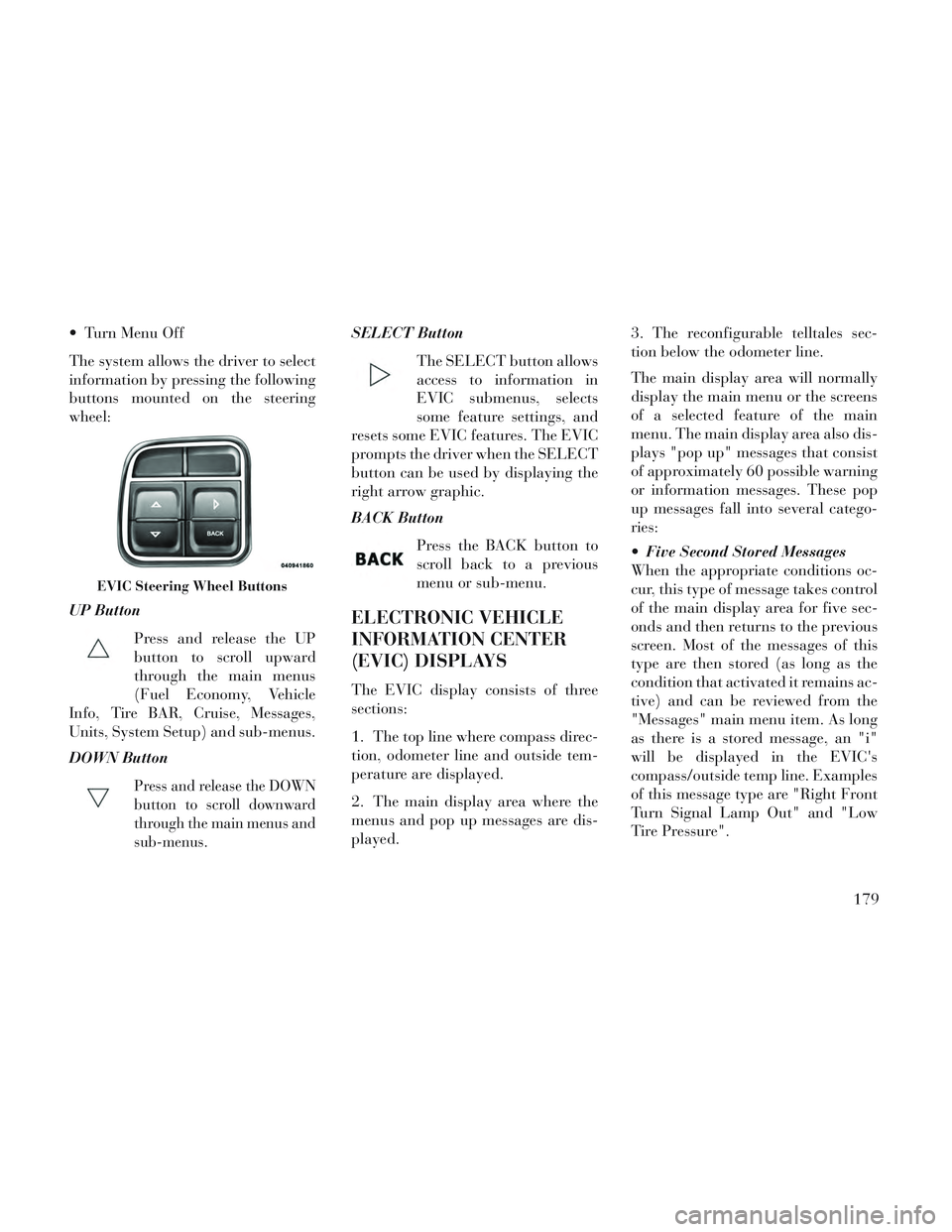
The system allows the driver to select
information by pressing the following
buttons mounted on the steering
wheel:
UP ButtonPress and release the UP
button to scroll upward
through the main menus
(Fuel Economy, Vehicle
Info, Tire BAR, Cruise, Messages,
Units, System Setup) and sub-menus.
DOWN Button
Press and release the DOWN
button to scroll downward
through the main menus and
sub-menus.
SELECT Button
The SELECT button allows
access to information in
EVIC submenus, selects
some feature settings, and
resets some EVIC features. The EVIC
prompts the driver when the SELECT
button can be used by displaying the
right arrow graphic.
BACK Button
Press the BACK button to
scroll back to a previous
menu or sub-menu.
ELECTRONIC VEHICLE
INFORMATION CENTER
(EVIC) DISPLAYS
The EVIC display consists of three
sections:
1. The top line where compass direc-
tion, odometer line and outside tem-
perature are displayed.
2. The main display area where the
menus and pop up messages are dis-
played. 3. The reconfigurable telltales sec-
tion below the odometer line.
The main display area will normally
display the main menu or the screens
of a selected feature of the main
menu. The main display area also dis-
plays "pop up" messages that consist
of approximately 60 possible warning
or information messages. These pop
up messages fall into several catego-
ries:
Five Second Stored Messages
When the appropriate conditions oc-
cur, this type of message takes control
of the main display area for five sec-
onds and then returns to the previous
screen. Most of the messages of this
type are then stored (as long as the
condition that activated it remains ac-
tive) and can be reviewed from the
"Messages" main menu item. As long
as there is a stored message, an "i"
will be displayed in the EVIC's
compass/outside temp line. Examples
of this message type are "Right Front
Turn Signal Lamp Out" and "Low
Tire Pressure".
EVIC Steering Wheel Buttons
179
Page 186 of 364
Unstored Messages
This message type is displayed indefi-
nitely or until the condition that acti-
vated the message is cleared. Ex-
amples of this message type are "Turn
Signal On" (if a turn signal is left on)
and "Lights On" (if driver leaves the
vehicle).
Unstored Messages Until RUN
This message type is displayed until
the ignition is in the RUN state. Ex-
ample of this message type is "Press
Brake Pedal and Push Button to
Start".
Five Second Unstored Messages
When the appropriate conditions oc-
cur, this type of message takes control
of the main display area for five sec-
onds and then returns to the previous
screen. Examples of this message type
are "Memory System Unavailable -
Not in Park" and "Automatic High
Beams On".
The Reconfigurable Telltales section
is divided into the white telltales area
on the right, amber telltales in the
middle, and red telltales on the left.When the appropriate conditions ex-
ist, the EVIC displays the following
messages:
Key in ignition
Ignition or Accessory On
Wrong Key
Damaged Key
Key not programmed
Vehicle Not in Park
Key Left Vehicle
Key Not Detected
Press Brake Pedal and Push Button
to Start
Liftgate Ajar (chime will sound when vehicle starts moving)
Low Tire Pressure
Service TPM System (refer to “Tire Pressure Monitoring System” in
“Starting And Operating”)
Premium system Tire Pressure dis- play screen With Low Tire(s) “In-
flate Tire to XX” Turn Signal On
RKE Battery Low
Service Keyless System
LOW WASHER FLUID
Oil Change Required
Check Gascap
Left Front Turn Signal Lamp Out
Left Rear Turn Signal Lamp Out
Right Front Turn Signal Lamp Out
Right Rear Turn Signal Lamp Out
Park Assist Disabled
Service Park Assist System
Personal Settings Not Available —
Vehicle Not in Park
Blind Spot System Off — This mes- sage is displayed when the ignition
is turned to ON to indicate the Blind
Spot System has been turned off.
Blind Spot System Not Available — This message is displayed to indi-
cate the Blind Spot Monitor (BSM)
system is temporarily unavailable
180
Page 217 of 364
incorrect playback, do not use these
extensions for any other types of
files.
For DivX files, only DivX Home Theater Profile Ver.3.0 is
supported.
Any file that is copy protected will not play. The Blu-ray player will
automatically skip the file and be-
gin playing the next available file.
Other compression formats such as Xvid and RMP4 will not play. The
Blu-ray player will automatically
skip the file and begin playing the
next available file.
For the lack of indexes DivX files, “Resume Play, “Fast Forward” and
“Fast Rewind” cannot be
supported.
DivX Home Theater Profile 3.0 re- quires:
Maximum resolution 720 x 480 @ 30fps or 720 x 576 @ 25fps
Minimum resolution 16 x 16 Maximum frame rate for pro-
gressive source 30 frames per
second
Maximum field rate for inter- laced source 60 fields per second
To change the current chapter, use the remote control’s or Blu-ray
player’s “Fast Forward” button to
advance to the next chapter, or the
“Fast Rewind” button to return to
the start of the current or previous
chapter.
DVD/Blu-ray/BD Region Codes
The VES™ DVD player/Blu-ray
player and many DVD/Blu-ray discs
are coded by geographic region. These
region codes must match in order for
the disc to play. If the region code for
the DVD/Blu-ray disc does not match
the region code for the player, the disc
will stop playing and a warning will
be displayed.
DVD Audio Support
When a DVD-Audio disc is inserted in
the VES™ DVD player, the DVD-
Audio title on the disc is played by
default (most DVD-Audio discs also have a Video title, but the Video title is
ignored). All multi - channel program
material is automatically mixed down
to two channels, which may result in a
lowered apparent volume level. If you
increase the volume level to account
for this change in level, remember to
lower the volume before changing the
disc or to another mode.
Recorded Discs
The VES™ DVD player will play
CD-R and CD-RW discs recorded in
CD-Audio or Video-CD format, or as
a CD-ROM containing MP3, WMA or
AAC (Blu-ray Disc Player only) files.
The player will also play DVD-Video
content recorded to a DVD-R or
DVD-RW disc. DVD-ROM discs (ei-
ther pressed or recorded) are not sup-
ported.
If you record a disc using a personal
computer, there may be cases where
the VES™ DVD player may not be
able to play some or the entire disc,
even if it is recorded in a compatible
211
Page 220 of 364
Using the remote control Up andDown cursor buttons, highlight the
Language item you want to edit,
and then press the remote control
ENTER/OK button.
Using the remote control Down cur- sor button, select the "Other" set-
ting, then press the remote control’s
Right cursor button to begin editing
the setting.
Using the remote control Up and Down cursor buttons, select a digit
for the current position. After se-
lecting the digit, press the remote
control’s Right cursor button to se-
lect the next digit. Repeat this digit
selection sequence for all four
digits.
When the entire four-digit code is entered, press the remote control’s
ENTER/OK button. If the language
code is not valid, the numbers all
change back to "*". If the digits are
visible after this step, then the lan-
guage code is valid.
Here is an abbreviated list of language
codes. For more language codes, please contact the dealer where the
vehicle was purchased.
Lan-
guage
Code Lan-
guageCode
Dutch 2311 French 1517
Ger-
man 1304 Ital-
ian1819
Portu-
guese 2519 Span-
ish1418
Rating and Password Setup
The Rating and Password settings
work together to control the types of
DVDs that your family watches. Most
DVD-Video discs have a rating (from
1 to 8) assigned to them where lower
numbers are designated for all audi-
ences and higher numbers are desig-
nated for more adult audiences.
When a DVD-Video disc is loaded, its
rating is compared to the setting in the
DVD player. If the rating of the disc is
higher than the setting in the player, a
Password screen is displayed. In order
to watch the disc, the rear passenger must enter the correct password using
the password entry method described
below.
To play all discs without requiring a
password, set the DVD player’s rating
to Level 8. Setting the rating to Level
1 always requires the password to
play any DVD disc. Not all DVD discs
encode a Rating, so it is still possible
that discs designed for adult audi-
ences can still play without requiring
a password.
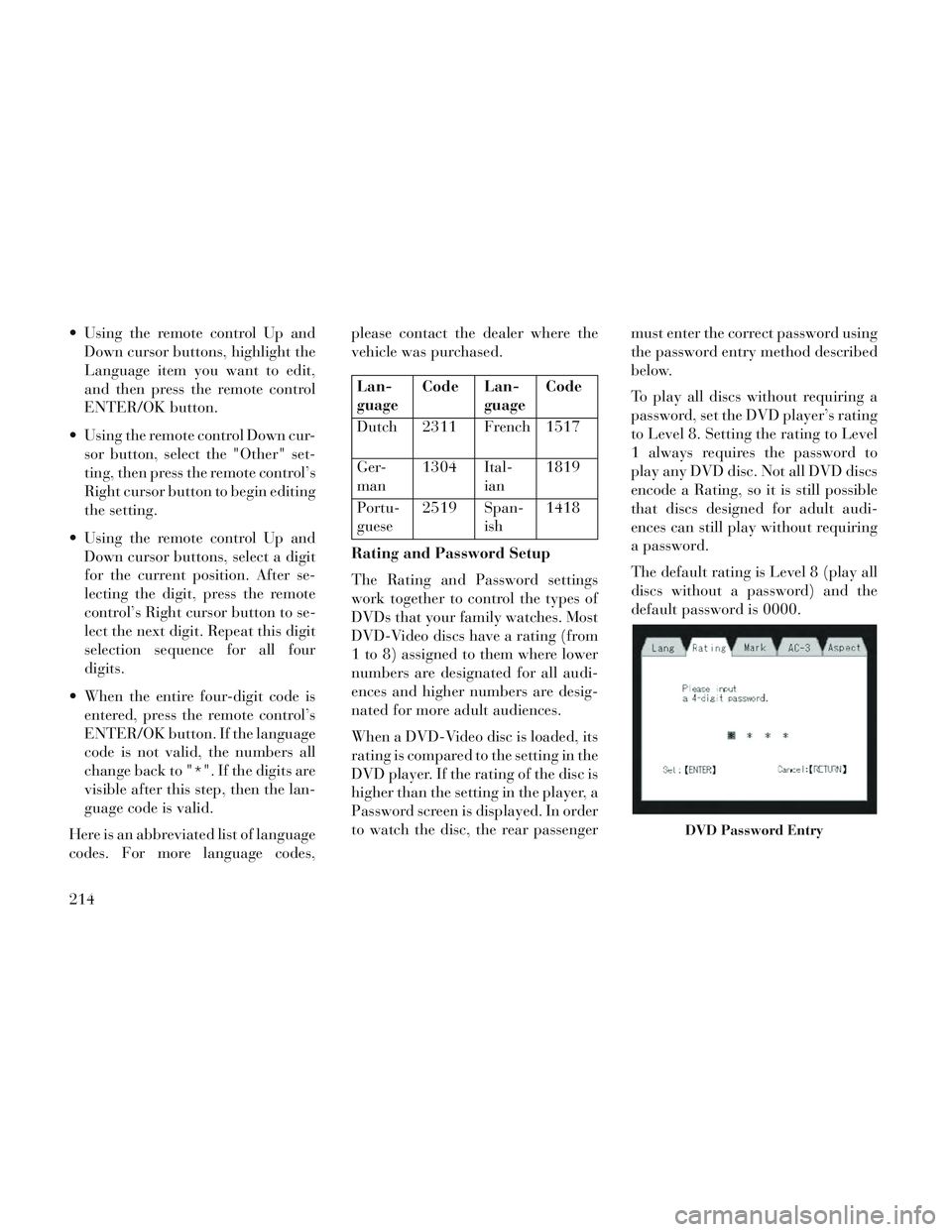
The default rating is Level 8 (play all
discs without a password) and the
default password is 0000.
DVD Password Entry
214
Page 234 of 364
PARKING BRAKE....................... .245
ANTI-LOCK BRAKE SYSTEM (ABS) ...........246
ANTI-LOCK BRAKE WARNING LIGHT . . . . . .247
ELECTRONIC BRAKE CONTROL SYSTEM (for versions/markets, where provided) ...........248
TRACTION CONTROL SYSTEM (TCS) (for versions/markets, where provided) .........248
BRAKE ASSIST SYSTEM (BAS) (for versions/ markets, where provided) ................249
ELECTRONIC STABILITY CONTROL (ESC) . .249
TRAILER SWAY CONTROL (TSC) ..........251
HILL START ASSIST (HSA) ...............252
TIRE SAFETY INFORMATION ...............252
Tire Markings ........................ .252
Tire Identification Number (TIN) ...........255
Tire Terminology And Definitions ...........256
Tire Loading And Tire Pressure ............256
TIRES — GENERAL INFORMATION ..........258
Tire Pressure ......................... .258
Tire Inflation Pressures ..................259
Tire Pressures For High Speed Operation . . . .260
Radial Ply Tires ....................... .260
Tire Types............................ .261
Run Flat Tires (for versions/markets, where provided) ............................ .261
Spare Tires (for versions/markets, where provided) ............................ .262
228
Page 253 of 364
modulate hydraulic pressure to pre-
vent wheel lock-up and help avoid
skidding on slippery surfaces.
ABS is activated during braking un-
der certain road or stopping condi-
tions. ABS-inducing conditions can
include ice, snow, gravel, bumps, rail-
road tracks, loose debris, or panic
stops.
You may experience the following
when the brake system goes into anti-
lock:
The ABS motor running (it maycontinue to run for a short time
after the stop).
A clicking sound of solenoid valves.
Brake pedal pulsations.
A slight drop or fall away of the brake pedal at the end of the stop.WARNING!
The Anti-Lock Brake Systemcontains sophisticated electronic
equipment that may be suscep-
tible to interference caused by
improperly installed, or high out-
put radio transmitting equip-
ment. This interference can cause
possible loss of anti-lock braking
capability. Installation of such
equipment should be performed
by qualified professionals.
Pumping of the Anti-Lock Brakes will diminish their effectiveness
and may lead to a collision.
Pumping makes the stopping dis-
tance longer. Just press firmly on
your brake pedal when you need
to slow down or stop.
The Anti-Lock Brake System cannot prevent collisions, includ-
ing those resulting from excessive
speed in turns, following another
vehicle too closely, or hydroplan-
ing.
(Continued)
WARNING!(Continued)
The capabilities of an ABS-equipped vehicle must never be
exploited in a reckless or danger-
ous manner, which could jeopar-
dize the user’s safety or the safety
of others.
The ABS cannot prevent the natural laws of physics from act-
ing on the vehicle, nor can it in-
crease braking or steering effi-
ciency beyond that afforded by
the condition of the vehicle
brakes and tires or the traction
afforded.
All vehicle wheels and tires must be
the same size and type, and tires must
be properly inflated to produce accu-
rate signals for the computer.
ANTI-LOCK BRAKE
WARNING LIGHT
The “Anti-Lock Brake
Warning Light” monitors
the anti-lock brake system.
The light will come on when
247
Page 265 of 364
WARNING!(Continued)
Over-inflation reduces a tire'sability to cushion shock. Objects
on the road and chuckholes can
cause damage that result in tire
failure.
Over-inflated or under-inflated tires can affect vehicle handling
and can fail suddenly, resulting in
loss of vehicle control.
Unequal tire pressures can cause steering problems. You could lose
control of your vehicle.
Unequal tire pressures from one side of the vehicle to the other can
cause the vehicle to drift to the
right or left.
Always drive with each tire in- flated to the recommended cold
tire inflation pressure.
Economy
Improper inflation pressures can
cause uneven wear patterns to de-
velop across the tire tread. These ab-
normal wear patterns will reduce
tread life resulting in a need for earlier
tire replacement. Under-inflation also increases tire rolling resistance result-
ing in higher fuel consumption.
Ride Comfort And Vehicle
Stability
Proper tire inflation contributes to a
comfortable ride. Over-inflation pro-
duces a jarring and uncomfortable
ride. Both under-inflation and over-
inflation affect the stability of the ve-
hicle and can produce a feeling of
sluggish response or over responsive-
ness in the steering.
NOTE:
Unequal tire pressures from side
to side may cause erratic and
unpredictable steering re-
sponse.
Unequal tire pressure from side to side may cause the vehicle to
drift left or right.
Tire Inflation Pressures
The proper cold tire inflation pressure
is listed on the driver's side “B” Pillar
or rear edge of the driver's side door. At least once a month:
Check and adjust tire pressure with
a good quality pocket-type pressure
gauge. Do not make a visual judge-
ment when determining proper in-
flation. Tires may look properly in-
flated even when they are under-
inflated.
Inspect tires for signs of tire wear or visible damage.
CAUTION!
After inspecting or adjusting the
tire pressure, always reinstall the
valve stem cap. This will prevent
moisture and dirt from entering the
valve stem, which could damage
the valve stem.
Inflation pressures specified on the
placard are always “cold tire inflation
pressure”. Cold tire inflation pressure
is defined as the tire pressure after the
vehicle has not been driven for at least
three hours, or driven less than
1.6 km after a three hour period. The
cold tire inflation pressure must not
259
Page 266 of 364

exceed the maximum inflation pres-
sure molded into the tire sidewall.
Check tire pressures more often if
subject to a wide range of outdoor
temperatures, as tire pressures vary
with temperature changes.
Tire pressures change by approxi-
mately 7 kPa per 7°C of air tempera-
ture change. Keep this in mind when
checking tire pressure inside a garage,
especially in the winter.
Example: If garage temperature =
20°C and the outside temperature =
0°C then the cold tire inflation pres-
sure should be increased by 21 kPa,
which equals 7 kPa for every 7°C for
this outside temperature condition.
Tire pressure may increase from 13 to
40 kPa during operation. DO NOT
reduce this normal pressure build up
or your tire pressure will be too low.Tire Pressures For High
Speed Operation
The manufacturer advocates driving
at safe speeds and within posted speed
limits. Where speed limits or condi-
tions are such that the vehicle can be
driven at high speeds, maintaining
correct tire inflation pressure is very
important. Increased tire pressure
and reduced vehicle loading may be
required for high-speed vehicle op-
eration. Refer to your authorized tire
dealer or original equipment vehicle
dealer for recommended safe operat-
ing speeds, loading and cold tire infla-
tion pressures.
WARNING!
High speed driving with your ve-
hicle under maximum load is dan-
gerous. The added strain on your
tires could cause them to fail. You
could have a serious collision. Do
not drive a vehicle loaded to the
maximum capacity at continuous
speeds above 120 km/h.
Radial Ply Tires
WARNING!
Combining radial ply tires with
other types of tires on your vehicle
will cause your vehicle to handle
poorly. The instability could cause
a collision. Always use radial ply
tires in sets of four. Never combine
them with other types of tires.
Tire Repair
If your tire becomes damaged, it may
be repaired if it meets the following
criteria:
The tire has not been driven on when flat.
The damage is only on the tread section of your tire (sidewall dam-
age is not repairable).
The puncture is no greater than 6 mm.
Consult an authorized tire dealer for
tire repairs and additional informa-
tion.
260