weight Lancia Voyager 2014 Owner handbook (in English)
[x] Cancel search | Manufacturer: LANCIA, Model Year: 2014, Model line: Voyager, Model: Lancia Voyager 2014Pages: 364, PDF Size: 3.49 MB
Page 56 of 364
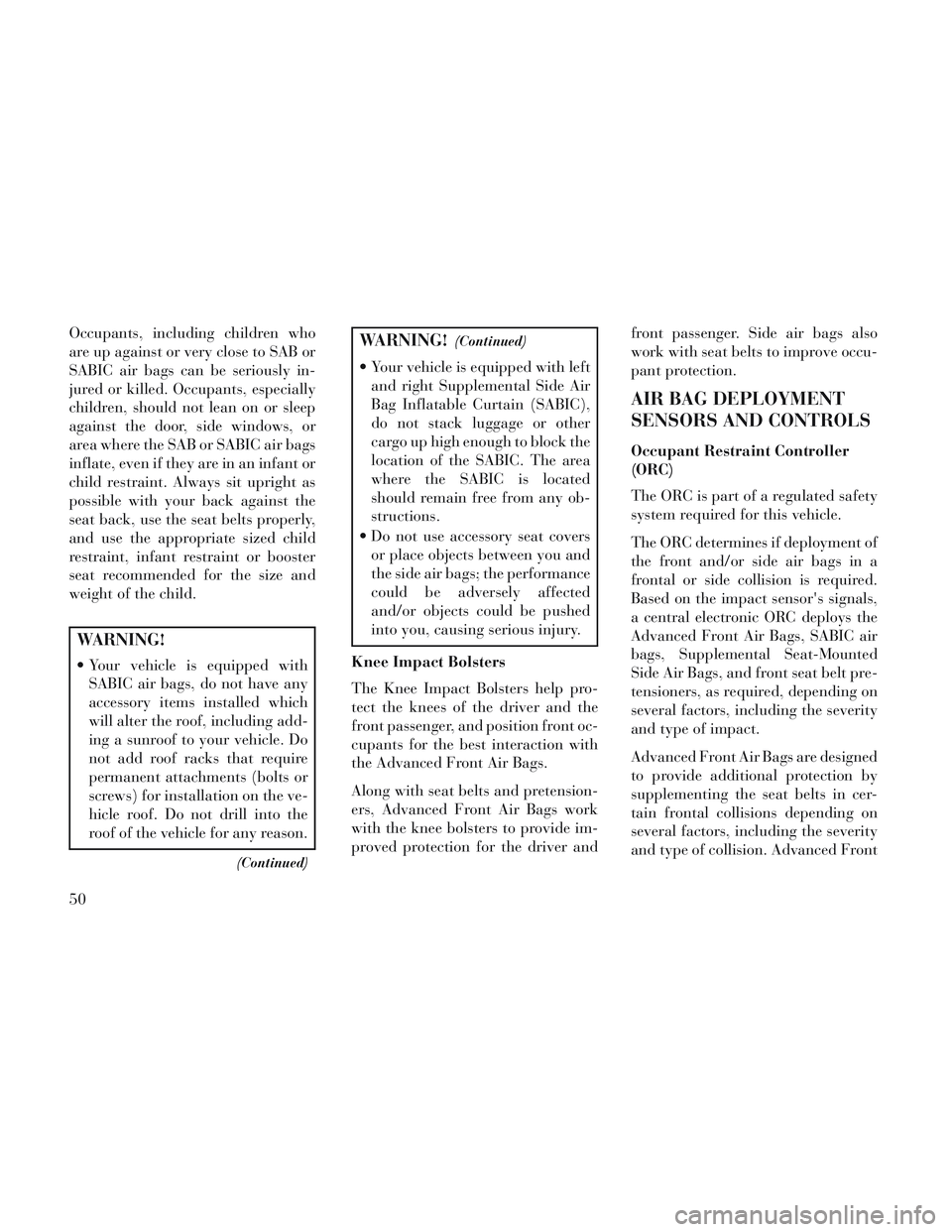
Occupants, including children who
are up against or very close to SAB or
SABIC air bags can be seriously in-
jured or killed. Occupants, especially
children, should not lean on or sleep
against the door, side windows, or
area where the SAB or SABIC air bags
inflate, even if they are in an infant or
child restraint. Always sit upright as
possible with your back against the
seat back, use the seat belts properly,
and use the appropriate sized child
restraint, infant restraint or booster
seat recommended for the size and
weight of the child.
WARNING!
Your vehicle is equipped withSABIC air bags, do not have any
accessory items installed which
will alter the roof, including add-
ing a sunroof to your vehicle. Do
not add roof racks that require
permanent attachments (bolts or
screws) for installation on the ve-
hicle roof. Do not drill into the
roof of the vehicle for any reason.
(Continued)
WARNING!(Continued)
Your vehicle is equipped with leftand right Supplemental Side Air
Bag Inflatable Curtain (SABIC),
do not stack luggage or other
cargo up high enough to block the
location of the SABIC. The area
where the SABIC is located
should remain free from any ob-
structions.
Do not use accessory seat covers or place objects between you and
the side air bags; the performance
could be adversely affected
and/or objects could be pushed
into you, causing serious injury.
Knee Impact Bolsters
The Knee Impact Bolsters help pro-
tect the knees of the driver and the
front passenger, and position front oc-
cupants for the best interaction with
the Advanced Front Air Bags.
Along with seat belts and pretension-
ers, Advanced Front Air Bags work
with the knee bolsters to provide im-
proved protection for the driver and front passenger. Side air bags also
work with seat belts to improve occu-
pant protection.
AIR BAG DEPLOYMENT
SENSORS AND CONTROLS
Occupant Restraint Controller
(ORC)
The ORC is part of a regulated safety
system required for this vehicle.
The ORC determines if deployment of
the front and/or side air bags in a
frontal or side collision is required.
Based on the impact sensor's signals,
a central electronic ORC deploys the
Advanced Front Air Bags, SABIC air
bags, Supplemental Seat-Mounted
Side Air Bags, and front seat belt pre-
tensioners, as required, depending on
several factors, including the severity
and type of impact.
Advanced Front Air Bags are designed
to provide additional protection by
supplementing the seat belts in cer-
tain frontal collisions depending on
several factors, including the severity
and type of collision. Advanced Front
50
Page 63 of 364
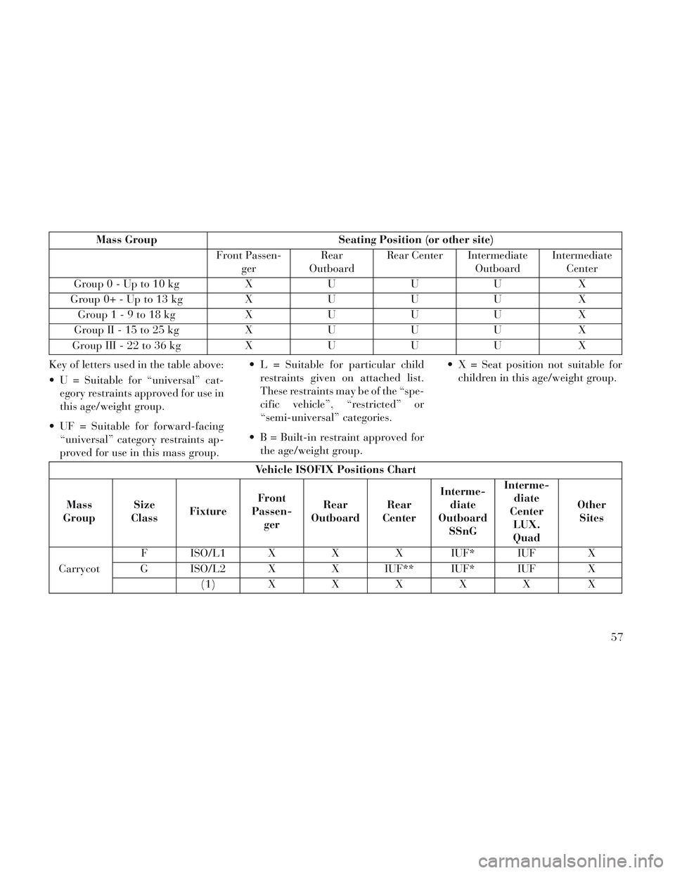
Mass GroupSeating Position (or other site)
Front Passen- ger Rear
Outboard Rear Center Intermediate
OutboardIntermediate
Center
Group0-Upto10kg XUUU X
G ro u p 0+ -U p to 13 kgXUUU X
Group1-9to18kg XUUU X
G ro u p II - 15 to 25 kgXUUU X
G ro u p III - 22 to 36 kgXUUU X
Key of letters used in the table above:
U = Suitable for “universal” cat- egory restraints approved for use in
this age/weight group.
UF = Suitable for forward-facing “universal” category restraints ap-
proved for use in this mass group. L = Suitable for particular child
restraints given on attached list.
These restraints may be of the “spe-
cific vehicle”, “restricted” or
“semi-universal” categories.
B = Built-in restraint approved for the age/weight group. X = Seat position not suitable for
children in this age/weight group.
Vehicle ISOFIX Positions Chart
Mass
Group Size
Class Fixture Front
Passen- ger Rear
Outboard Rear
Center Interme-
diate
Outboard SSnG Interme-
diate
Center LUX.
Quad Other
Sites
Carrycot F ISO/L1 X
XX IUF* IUF X
G ISO/L2 X X IUF** IUF* IUF X
( 1 )XXXXX X
57
Page 65 of 364
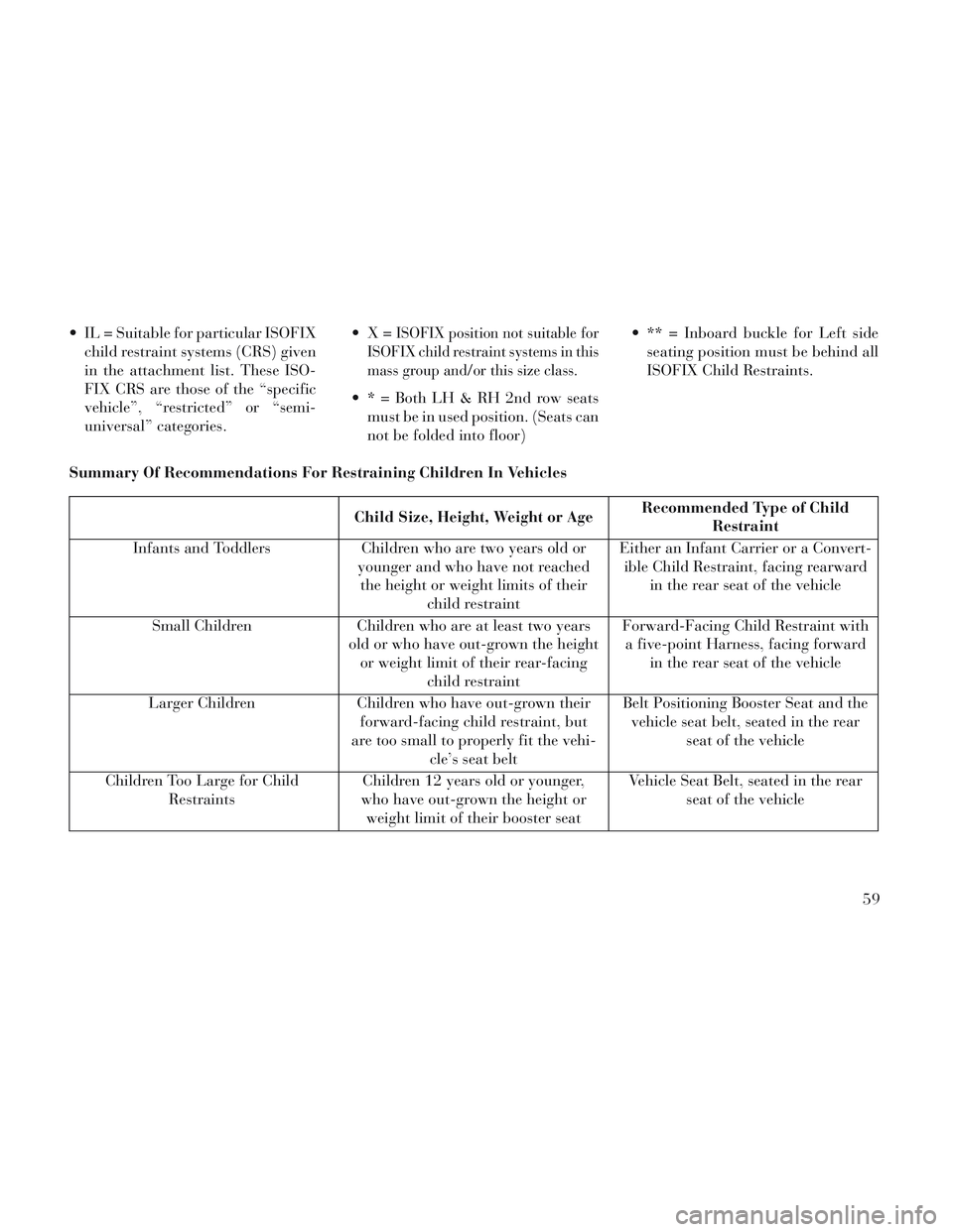
IL = Suitable for particular ISOFIXchild restraint systems (CRS) given
in the attachment list. These ISO-
FIX CRS are those of the “specific
vehicle”, “restricted” or “semi-
universal” categories. ISOFIX position not suitable for
ISOFIX child restraint systems in this
mass group and/or this size class.
* = Both LH & RH 2nd row seats must be in used position. (Seats can
not be folded into floor) ** = Inboard buckle for Left side
seating position must be behind all
ISOFIX Child Restraints.
Summary Of Recommendations For Restraining Children In Vehicles
Child Size, Height, Weight or Age Recommended Type of Child
Restraint
Infants and Toddlers Children who are two years old or
younger and who have not reached the height or weight limits of their child restraint Either an Infant Carrier or a Convert-
ible Child Restraint, facing rearward in the rear seat of the vehicle
Small Children Children who are at least two years
old or who have out-grown the height or weight limit of their rear-facing child restraint Forward-Facing Child Restraint with
a five-point Harness, facing forward in the rear seat of the vehicle
Larger Children Children who have out-grown their
forward-facing child restraint, but
are too small to properly fit the vehi- cle’s seat belt Belt Positioning Booster Seat and the
vehicle seat belt, seated in the rear seat of the vehicle
Children Too Large for Child Restraints Children 12 years old or younger,
who have out-grown the height or weight limit of their booster seat Vehicle Seat Belt, seated in the rear
seat of the vehicle
59
Page 66 of 364
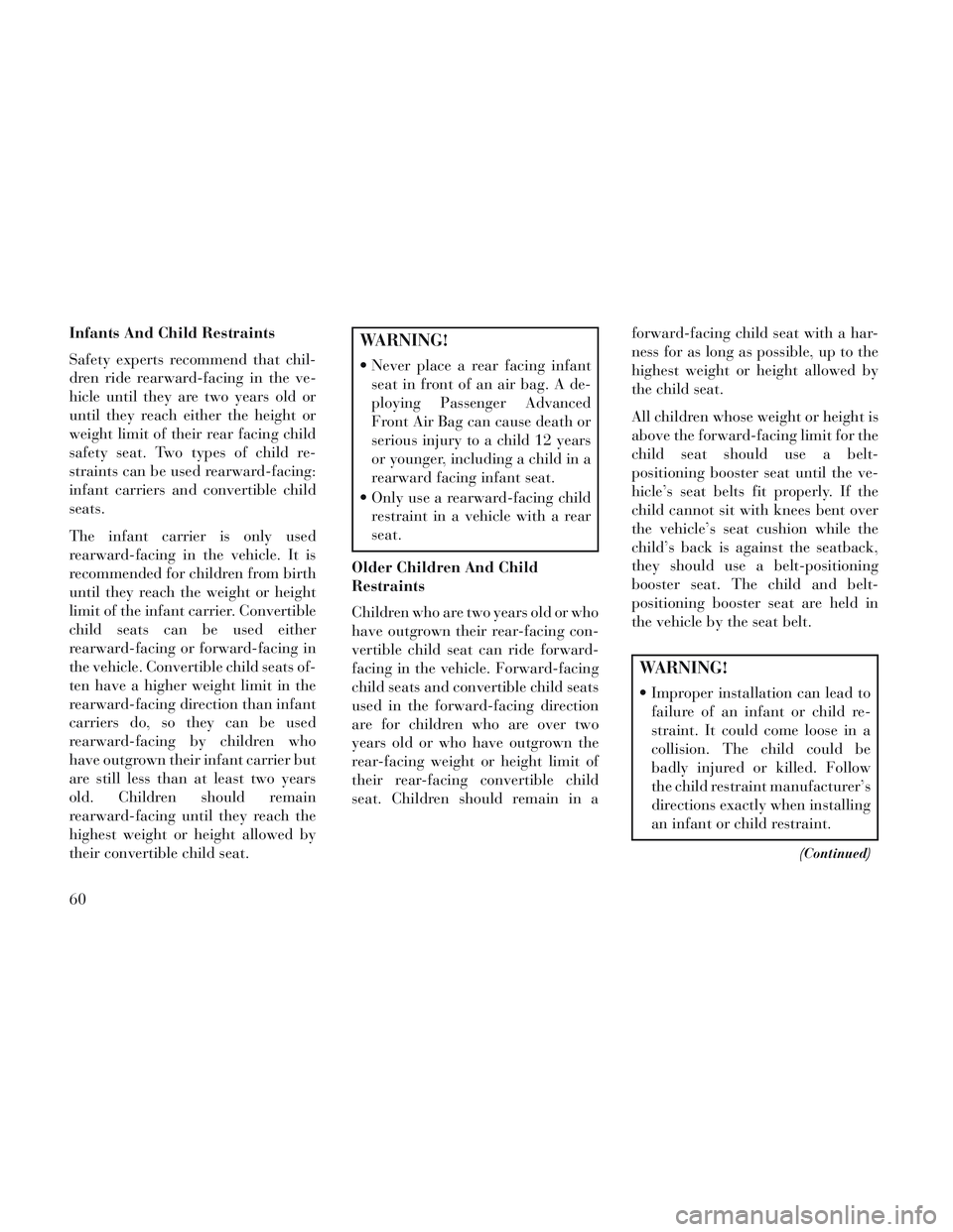
Infants And Child Restraints
Safety experts recommend that chil-
dren ride rearward-facing in the ve-
hicle until they are two years old or
until they reach either the height or
weight limit of their rear facing child
safety seat. Two types of child re-
straints can be used rearward-facing:
infant carriers and convertible child
seats.
The infant carrier is only used
rearward-facing in the vehicle. It is
recommended for children from birth
until they reach the weight or height
limit of the infant carrier. Convertible
child seats can be used either
rearward-facing or forward-facing in
the vehicle. Convertible child seats of-
ten have a higher weight limit in the
rearward-facing direction than infant
carriers do, so they can be used
rearward-facing by children who
have outgrown their infant carrier but
are still less than at least two years
old. Children should remain
rearward-facing until they reach the
highest weight or height allowed by
their convertible child seat.WARNING!
Never place a rear facing infantseat in front of an air bag. A de-
ploying Passenger Advanced
Front Air Bag can cause death or
serious injury to a child 12 years
or younger, including a child in a
rearward facing infant seat.
Only use a rearward-facing child restraint in a vehicle with a rear
seat.
Older Children And Child
Restraints
Children who are two years old or who
have outgrown their rear-facing con-
vertible child seat can ride forward-
facing in the vehicle. Forward-facing
child seats and convertible child seats
used in the forward-facing direction
are for children who are over two
years old or who have outgrown the
rear-facing weight or height limit of
their rear-facing convertible child
seat. Children should remain in a forward-facing child seat with a har-
ness for as long as possible, up to the
highest weight or height allowed by
the child seat.
All children whose weight or height is
above the forward-facing limit for the
child seat should use a belt-
positioning booster seat until the ve-
hicle’s seat belts fit properly. If the
child cannot sit with knees bent over
the vehicle’s seat cushion while the
child’s back is against the seatback,
they should use a belt-positioning
booster seat. The child and belt-
positioning booster seat are held in
the vehicle by the seat belt.
WARNING!
Improper installation can lead to
failure of an infant or child re-
straint. It could come loose in a
collision. The child could be
badly injured or killed. Follow
the child restraint manufacturer’s
directions exactly when installing
an infant or child restraint.
(Continued)
60
Page 68 of 364
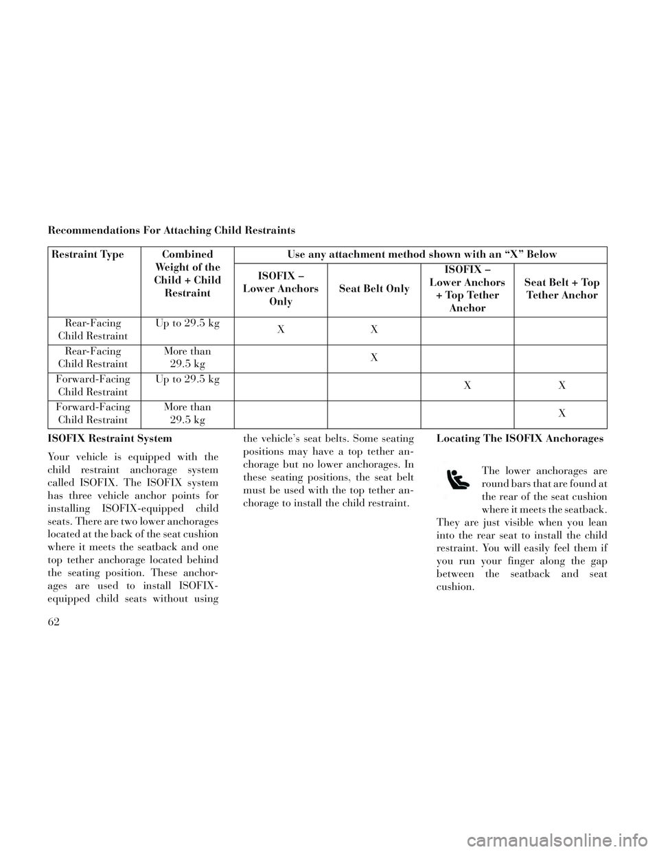
Recommendations For Attaching Child Restraints
Restraint Type CombinedWeight of the
Child + Child Restraint Use any attachment method shown with an “X” Below
ISOFIX –
Lower Anchors Only Seat Belt Only ISOFIX –
Lower Anchors + Top Tether Anchor Seat Belt + Top
Tether Anchor
Rear-Facing
Child Restraint Up to 29.5 kg
XX
Rear-Facing
Child Restraint More than
29.5 kg X
Forward-Facing Child Restraint Up to 29.5 kg
XX
Forward-Facing Child Restraint More than
29.5 kg X
ISOFIX Restraint System
Your vehicle is equipped with the
child restraint anchorage system
called ISOFIX. The ISOFIX system
has three vehicle anchor points for
installing ISOFIX-equipped child
seats. There are two lower anchorages
located at the back of the seat cushion
where it meets the seatback and one
top tether anchorage located behind
the seating position. These anchor-
ages are used to install ISOFIX-
equipped child seats without using the vehicle’s seat belts. Some seating
positions may have a top tether an-
chorage but no lower anchorages. In
these seating positions, the seat belt
must be used with the top tether an-
chorage to install the child restraint.
Locating The ISOFIX Anchorages
The lower anchorages are
round bars that are found at
the rear of the seat cushion
where it meets the seatback.
They are just visible when you lean
into the rear seat to install the child
restraint. You will easily feel them if
you run your finger along the gap
between the seatback and seat
cushion.
62
Page 131 of 364

To Unfold Third Row Seats
1. Pull up on the assist strap to lift
the seat out of the storage bin and
push the seat forward until the an-
chors latch.
2. Pull release strap marked “2” to
unlock the recliner.
3. Pulling strap “4” releases the seat-
back to return to its full upright posi-
tion.
4. Raise the head restraint to its up-
right position.
WARNING!
In a collision, you or others inyour vehicle could be injured if
seats are not properly latched to
their floor attachments. Always
be sure the seats are fully latched.
Sitting in a seat with the head restraint in its lowered position
could result in serious injury or
death in a collision. Always make
sure the head restraints are in
their upright positions when the
seat is to be occupied. Tailgate Mode
1. Pull release strap “3”, then pull
release strap “4” to rotate the entire
seat rearward.
2. To restore the seat to its upright
position, lift up on the seatback and
push forward until the anchors latch.
WARNING!
To avoid serious injury or death,
never operate the vehicle with oc-
cupants in the third row seat while
in the tailgate mode.
PLASTIC GROCERY BAG
RETAINER HOOKS
Retainer hooks which will hold plastic
grocery bag handles are built into the
seatbacks of all rear seats and some
front seats. The floor supports the
partial weight of the bagged goods.
DRIVER MEMORY SEAT
(for versions/markets,
where provided)
The Memory Buttons 1 and 2 on the
driver's door panel can be pro-
grammed to recall the driver's seat,
driver's outside mirror, adjustable
brake and accelerator pedals, and ra-
dio station preset settings. Your Re-
mote Keyless Entry (RKE) transmit-
ters can also be programmed to recall
the same positions when the UN-
LOCK button is pressed.
Your vehicle may have been delivered
with two RKE transmitters. Only one
RKE transmitter can be linked to each
of the memory positions.
Driver Memory Switch
125
Page 138 of 364

from low beams to high beams. Pull-
ing back to the neutral position re-
turns the headlights to the low beam
operation.
FLASH-TO-PASS
You can signal another vehicle with
your headlights by lightly pulling the
multifunction lever toward you. This
will turn on the high beam headlights
until the lever is released.
AUTOMATIC HIGH BEAM
(for versions/markets,
where provided)
The Automatic High Beam system
provides increased forward lighting at
night by automating high beam con-
trol through the use of a digital cam-
era mounted on the inside rearview
mirror. This camera detects vehicle
specific light and automatically
switches from high beams to low
beams until the approaching vehicle
is out of view.
NOTE: Broken, muddy or ob-
structed headlights and taillights
of vehicles in the field of view willcause headlights to remain on lon-
ger (closer to the vehicle). Also,
dirt, film and other obstructions
on the windshield or camera lens
will cause the system to function
improperly.
To Activate
1. Select “Automatic High Beams —
ON” through the EVIC. Refer to
“Electronic Vehicle Information Cen-
ter (EVIC)/Customer-Programmable
Features” in “Understanding Your In-
strument Panel” for further informa-
tion.
2. Rotate the headlight switch coun-
terclockwise to the AUTO (A) posi-
tion.
3. Push the multifunction lever away
from you to switch the headlights to
the high beam position. Refer to
“Multifunction Lever” in this section
for further information.
NOTE: This system will not acti-
vate until the vehicle is at, or
above, 40 km/h.
HEADLIGHT LEVELING
SYSTEM (for versions/
markets, where provided)
Your vehicle may be
equipped with a headlight
leveling system. This sys-
tem allows the driver to
maintain proper headlight beam posi-
tion with the road surface regardless
of vehicle load. The control switch is
located on the instrument panel next
to the dimmer control.
To operate, rotate the control switch
until the appropriate number, which
corresponds to the load listed on the
chart, aligns with the indicator line on
the switch.
0 Driver only, or driver and
front passenger.
1 Driver, plus an evenly distrib-
uted load in the luggage com- partment. The total weight of the driver and load does not exceed the maximum load capacity of the vehicle.
132
Page 139 of 364

2All seating positions occupied,
plus an evenly distributed
load in the luggage compart-
ment. The total weight of pas-
sengers and load does not ex-
ceed the maximum load
capacity of the vehicle.
Calculations based on a passenger weight of 75 kg.
WINDSHIELD WIPERS
AND WASHERS
The wipers and washers are operated
by a switch within the multifunction
lever. Rotate the end of the multifunc-
tion lever to select the desired wiper
speed. NOTE: Always remove any
buildup of snow that prevents the
windshield wiper blades from re-
turning to the off position. If the
windshield wiper switch is turned
off and the blades cannot return to
the off position, damage to the
wiper motor may occur.
WARNING!
Sudden loss of visibility through
the windshield could lead to a col-
lision. You might not see other ve-
hicles or other obstacles. To avoid
sudden icing of the windshield dur-
ing freezing weather, warm the
windshield with the defroster be-
fore and during windshield washer
use.
MIST, FRONT WIPER AND
WASHER
Use the Mist feature when weather
conditions make occasional usage of
the wipers necessary.
Press the end of the multifunction lever
inward (toward the steering column) to
the first detent and release for a single wiping cycle. To use the Washer, push
on the end of the lever to the second
detent and hold while spray is desired.
If the lever is pushed while on the in-
termittent setting, the wipers will turn
on and operate for several wipe cycles
after the lever is released, and then
resume the intermittent interval previ-
ously selected. If the lever is pushed
while the wipers are in the off position,
the wipers will operate several wipe
cycles, then turn off.
INTERMITTENT, LOW AND
HIGH SPEED WIPERS
Rotate the end of the lever to one of
the first five detent positions for inter-
mittent wiper operation, the sixth de-
tent for low wiper operation and the
seventh detent for high wiper opera-
tion.
Use one of the five intermittent wiper
settings when weather conditions
make a single wiping cycle, with a
variable delay between cycles, desir-
able. At driving speeds above
16 km/h, the delay can be regulated
from a maximum of approximately
Washer And Wiper Controls
133
Page 167 of 364

To prevent excessive batterydrain, use the rear window de-
froster only when the engine is
operating.
CAUTION!
Failure to follow these cautions can
cause damage to the heating ele-
ments:
Use care when washing the insideof the rear window. Do not use
abrasive window cleaners on the
interior surface of the window.
Use a soft cloth and a mild wash-
ing solution, wiping parallel to
the heating elements. Labels can
be peeled off after soaking with
warm water.
Do not use scrapers, sharp instru- ments, or abrasive window clean-
ers on the interior surface of the
window.
Keep all objects a safe distance from the window.
ROOF LUGGAGE RACK
(for versions/markets,
where provided)
The crossbars on your vehicle are de-
livered stowed within the roof rack
side rails. If adding cargo, deploy the
crossbars. Distribute cargo weight
evenly on the roof rack crossbars, to
maximum of 68 kg. The roof rack
does not increase the total load carry-
ing capacity of the vehicle. Be sure the
total load of cargo inside the vehicle
plus that on the external rack does not
exceed the maximum vehicle load ca-
pacity.
The crossbars and side rails are de-
signed to carry weight on vehicles
equipped with a luggage rack. The load must not exceed 68 kg, and
should be uniformly distributed over
the luggage rack crossbars.
NOTE:
Crossbars are error-proofed and
cannot be deployed or stowed in
the incorrect positions.
To help control wind noise, stow the crossbars in the side rails
when they are not in use.
DEPLOYING THE
CROSSBARS
To deploy the crossbars, completely
loosen the thumb screws at both ends
of the crossbar and lift the crossbar
from its stowed position in the side
rail. Repeat with crossbar on the op-
posite side.
Crossbar Stowed In Side Rail
Loosening Crossbars
161
Page 191 of 364

Distance To Empty (DTE)
Shows the estimated distance that can
be traveled with the fuel remaining in
the tank. This estimated distance is
determined by a weighted average of
the instantaneous and average fuel
economy, according to the current
fuel tank level. DTE cannot be reset
through the SELECT button.
NOTE: Significant changes in
driving style or vehicle loading
will greatly affect the actual driv-
able distance of the vehicle, re-
gardless of the DTE displayed
value.
When the DTE value is less than
48 km estimated driving distance, the
DTE display will change to a “LOW
FUEL” message. This display will
continue until the vehicle runs out offuel. Adding a significant amount of
fuel to the vehicle will turn off the
“LOW FUEL” message and a new
DTE value will display.
Instantaneous Fuel Economy (IFE)
This display shows the instantaneous
Liters Per 100km (L/100km)
or Miles Per Gallon (MPG) in bar
graph form while driving. This will
monitor the gas mileage in real-time
as you drive and can be used to
modify driving habits in order to in-
crease fuel economy.
VEHICLE SPEED
Press and release the UP or DOWN
button until “Vehicle Speed” displays
highlighted in the EVIC and press the
SELECT button. Press the SELECT
button to display the current speed
in km/h or mph. Pressing the SE-
LECT button a second time will
toggle the unit of measure
between km/h or mph.
NOTE: Changing the unit of mea-
sure in the Vehicle Speed menu
will not change the unit of measure
in the EVIC.
TRIP INFO
Press and release the UP or DOWN but-
ton until “Trip Info” is highlighted in
the EVIC and press the SELECT but-
ton. Press and release the UP/DOWN
buttons to highlight one of the following
functions if you want to reset it:
Trip A
Shows the total distance traveled for
Trip A since the last reset.
Trip B
Shows the total distance traveled for
Trip B since the last reset.
Elapsed Time
Shows the total elapsed time of travel
since the last reset when the ignition
switch is in the ACC position. Elapsed
time will increment when the ignition
switch is in the ON or START position.
To Reset A Trip Function
Reset will only occur while a reset-
table function is selected (high-
lighted). Press and hold the SELECT
button to clear the resettable function
being displayed.
Average Fuel Economy Display
185