Lancia Ypsilon 2001 Owner handbook (in English)
Manufacturer: LANCIA, Model Year: 2001, Model line: Ypsilon, Model: Lancia Ypsilon 2001Pages: 191, PDF Size: 2.45 MB
Page 51 of 191

48
G
A key C (fig. 67)is attached to the
back of the cover B (fig. 67); insert
this key into D (fig. 68) and turn it to
manually perform the operations de-
scribed previously (opening/closing).
To reach D, remove the press-fitted
cover.
fig. 68
P4C00187
Do not open the roof if
there is snow or ice on it as
you risk damaging it.
SUNROOF
The sunroof is electrically operated.
It will only work if the ignition key
is at MAR.
ButtonA (fig. 65)on the ceiling light
unit controls the opening, closing,
raising and lowering of the roof.
When you release the button, the
roof locks in the position it is in at
that moment.
£Press once to open in the spoiler
position.
Press again to open completely.
¢Press to close.
fig. 65
P4C00101
A sliding sunshade, fitted under the
sunroof, will lessen the effect of the
sun’s rays or the amount of air enter-
ing the car (fig. 66).
If there is an electrical fault in the
sunroof, open the glove compartment.
fig. 66
P4C00102
fig. 67
P4C00103
4C001-067 ING 11-03-2008 11:57 Pagina 48
Page 52 of 191

49
G
DOORS
SIDE DOORS CENTRAL
LOCKING/UNLOCKING
Unlocking from the outside
Insert the key into one of the two
doors and turn it to position 2
(fig. 69), then lift the door handle. Only open or close the
sunroof when the car is
stationary.
Incorrect use of the sun-
roof could be dangerous.
Before and when pressing
the switch, always make sure that
passengers are not liable to injury
either directly by the movement of
the sunroof or by personal effects
being dragged along or knocked
by the roof.
Always remove the igni-
tion key when getting out
of the car to make sure
that the sunroof cannot be acci-
dentally operated and constitute a
hazard for passengers remaining
in the car.
fig. 69
P4C00020
Before opening a door,
make sure that the condi-
tions are safe to carry out
the manoeuvre.
Locking from the outside
Turn the key to position 1 (fig. 69).
Opening/locking the doors
from the inside
With the doors closed, press (to
lock) or lift (to unlock) the door open-
ing lever A (fig. 70)on either the dri-
ver’s or the passenger’s side.
A green sector B(covered when the
lock is off) will appear when the door
is locked (lever Adown). The instru-
ment panel warning light
´may light
up if the doors are not closed perfectly
in some versions.
fig. 70
P4C00019
4C001-067 ING 11-03-2008 11:57 Pagina 49
Page 53 of 191

50
G
Incorrect use of the elec-
tric windows could be
dangerous. Before and
when pressing the switches, always
make sure that passengers are not
liable to injury either directly by
the movement of the windows or
by personal effects being dragged
along or knocked by the windows.
Always remove the ignition key
when getting out of the car to make
sure that the electric windows can-
not be accidentally operated and
constitute a hazard for passengers
remaining in the car.
The door handle on the passenger
side has a button to control that par-
ticular window. IMPORTANTFor versions with
door locking/unlocking remote con-
trol, see the “Lancia CODE system -
Door lock/unlock remote control”
paragraph at the beginning of this
chapter.
IMPORTANTIf one of the doors is
not shut properly or there is a failure
in the system, the central locking fea-
ture will not work and, after some at-
tempts, the device stops working for
around two minutes. In these two min-
utes the doors can be locked or un-
locked manually without the electrical
system coming into play. After the two
minutes, the control unit is ready to
receive commands once more.
If the reason for the malfunction has
been removed, the device will start to
work properly again. If not, it will cut
out once more.ELECTRIC WINDOWS
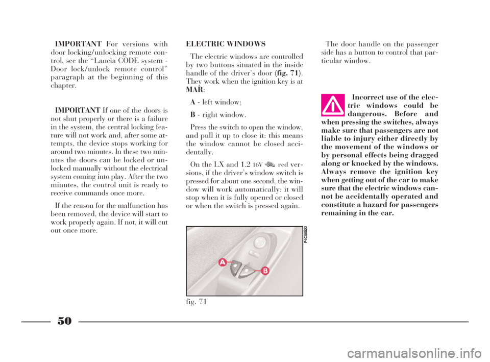
The electric windows are controlled
by two buttons situated in the inside
handle of the driver’s door (fig. 71).
They work when the ignition key is at
MAR:
A- left window;
B- right window.
Press the switch to open the window,
and pull it up to close it: this means
the window cannot be closed acci-
dentally.
On the LX and 1.2
16VM M Nredver-
sions, if the driver’s window switch is
pressed for about one second, the win-
dow will work automatically: it will
stop when it is fully opened or closed
or when the switch is pressed again.
fig. 71
P4C00022
4C001-067 ING 11-03-2008 11:57 Pagina 50
Page 54 of 191

51
G
BOOT
OPENING/CLOSING
THE TAILGATE
To open the boot from the outside,
unlock it with the ignition key A
(fig. 72).
To open it from inside the car, pull
leverA (fig. 73)at the side of the dri-
ver’s seat.
To lift the tailgate, use the grip lo-
cated between the two number plate
lights.When the tailgate is closed, it will
lock automatically, and can only be
reopened by using the key or pulling
leverA (fig. 73)inside the car.
IMPORTANTNever leave the keys
in the boot.
Use the handle situated in the inte-
rior trim of the tailgate A (fig. 74)to
lower it without getting your hands
dirty.
To close the tailgate, lower it and
press in the centre until you hear it
lock.
fig. 72
P4C00021
fig. 73
P4C00015
Do not work boot release
lever when the car is in
motion.
The addition of objects to
the rear parcel shelf or
tailgate (loudspeakers,
spoiler, etc.) may prevent the gas-
filled struts at the sides of the tail-
gate working properly. Items
arranged on the rear window shelf
could be thrown forwards and in-
jure passengers should you brake
sharply.
fig. 74
P4C00037
When using the boot,
make sure the load you are
carrying does not exceed
the permitted weight (see the
“Technical specifications” sec-
tion). Also ensure the items in the
boot are arranged properly to pre-
vent them being thrown forward
and injurying passengers should
you brake sharply.
4C001-067 ING 11-03-2008 11:57 Pagina 51
Page 55 of 191

52
G
4)Fold the seat back forwards to
make a flat loading surface with the
boot floor (fig. 78).
If necessary, the cushion can also be
tilted(fig. 79). Consequently, before
releasing the seat back, lift the cush-
ion as shown and tip it against the
front seat backs; the rear seat back-
rest can then be released and tilted
forwards.
To return the seat to its normal po-
sition:
1)Return the seat back to the verti-
cal position and make sure it is prop-
erly locked into place; the red strip on
the hook-up button must disappear.
fig. 77
P4C00034
Removing the parcel shelf
If you wish to remove the parcel
shelf to extend the boot capacity, un-
hook the two tie-rods (one each side)
A (fig. 75)from the hooks B, then
pull the parcel shelf outwards so that
pinsCcome out.
The shelf can then be positioned be-
hind the front seats.INCREASING THE LOAD AREA
Proceed as follows:
1)Make sure that the side seat belts
A (fig. 76)have been inserted into the
corresponding bracket B.
2)Remove the rear head restraints
if required.
3)Release the seat back by pressing
buttonA (fig. 77)(one for each side)
located on the back seat back-rest
(even when a split back seat is fitted);
a red strip will appear on the short
side of the button (towards the inside
of the car) to indicate that it has been
released.
fig. 75
P4C00009
fig. 76
P4C00052
Heavy loads which are
not securely anchored
could seriously injure pas-
sengers in the event of an accident.
4C001-067 ING 11-03-2008 11:57 Pagina 52
Page 56 of 191

53
G
2)Tip back the cushion while hold-
ing up the ends of the seat belts
(tongues and buckles) and passing
them between cushion and seat back.
In this way, the seat belts will be im-
mediately ready to be used.
Some versions fit a split rear seat. In
this case, the left-hand side and the
right-hand side of the seat can be
tipped separately.IMPORTANTWhen driving at
night with a load in the boot, adjust
the height of the dipped headlight
beam as shown in “Headlights” in
this chapter.
For correct adjustment, make sure
the load does not exceed the values in-
dicated in the relevant section.
fig. 78
P4C00160
fig. 79
P4C00051
If the backrest is not fas-
tened properly, heavy
loose luggage behind it
could cause serious harm to pas-
sengers in the event of an accident.If you wish to carry a re-
serve can of petrol, it is
important to comply to the
laws in force. Use only a homolo-
gated can and fasten it securely.
Even so, there is a greater fire risk
in the event of an accident.
BONNET
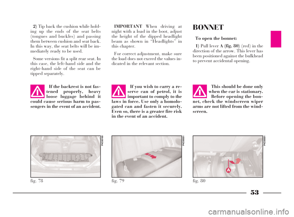
To open the bonnet:
1)Pull lever A (fig. 80)(red) in the
direction of the arrow. This lever has
been positioned against the bulkhead
to prevent accidental opening.
fig. 80
P4C00001
This should be done only
when the car is stationary.
Before opening the bon-
net, check the windscreen wiper
arms are not lifted from the wind-
screen.
4C001-067 ING 11-03-2008 11:57 Pagina 53
Page 57 of 191

54
G
To close the bonnet:
1)Hold the bonnet up with one
hand and, with the other, remove rod
A (fig. 82)from recess Cand replace
it in its clip B.
2)Lower the bonnet until it is about
20 cm (8 ins) above the engine com-
partment.
3)Let it fall: the bonnet closes auto-
matically.
Always make sure the
bonnet is closed properly
so it will not open while
travelling.
2)Lift lever B (fig. 81).
3)Lift the bonnet, and release the
support rod A (fig. 82)from its clip B.
4)Place the tip of the support rod in
recessCof the bonnet.
fig. 81
P4C00005
Important. The bonnet
might fall violently if the
support rod is not posi-
tioned properly.
Scarves, ties and loose
garmets can get caught in
moving parts. This can be
extremely dangerous.
fig. 82
P4C00006
If repairs need to be car-
ried out inside the engine
compartment when this is
still hot, be careful not to burn
yourself and keep away from the
electric fan as this may cut in at
any time, even if the key is re-
moved from the ignition switch.
Wait until the engine has cooled.
4C001-067 ING 11-03-2008 11:57 Pagina 54
Page 58 of 191

55
G
SKI AND
ROOF RACKS
ANCHORAGE HOOKS
POSITIONING
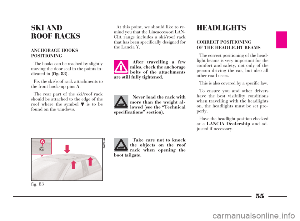
The hooks can be reached by slightly
moving the door seal in the points in-
dicated in (fig. 83).
Fix the ski/roof rack attachments to
the front hook-up pins A.
The rear part of the ski/roof rack
should be attached to the edge of the
roof where the symbol
Vis to be
found on the windows.At this point, we should like to re-
mind you that the Lineaccessori LAN-
CIA range includes a ski/roof rack
that has been specifically designed for
the Lancia Y.
fig. 83
P4C00104
After travelling a few
miles, check the anchorage
bolts of the attachments
are still fully tightened.
Never load the rack with
more than the weight al-
lowed (see the “Technical
specifications” section).
Take care not to knock
the objects on the roof
rack when opening the
boot tailgate.
HEADLIGHTS
CORRECT POSITIONING
OF THE HEADLIGHT BEAMS
The correct positioning of the head-
light beams is very important for the
comfort and safety, not only of the
person driving the car, but also all
other road users.
This is also covered by a specific law.
To ensure you and other drivers
have the best visibility conditions
when travelling with the headlights
on, the headlights must be set pro-
perly.
Have the headlight position checked
at a LANCIA Dealershipand ad-
justed if necessary.
4C001-067 ING 11-03-2008 11:57 Pagina 55
Page 59 of 191

56
G
ABS
The car is fitted with an ABS brak-
ing system that prevents the wheels
locking when braking, it exploits the
grip on the road surface holding the
car in the case of sudden braking.
The driver becomes aware of the
ABS activation through a slight throb-
bing of the brake pedal and the rele-
vant noise it makes.
This does not indicate brake mal-
functioning, it is an indication to the
driver that the ABS is operating. It is
a warning that the car is travelling at
borderline road grip and therefore the
speed should be adjusted to the type
of road surface.
The ABS is an addition to the basic
braking system; in the case of a fail-
ure it disables, leaving the braking
system in the same conditions as a ve-
hicle without ABS installed. COMPENSATION
FOR THE UPWARD SLANT
OF THE HEADLIGHT BEAMS
When the car is loaded, it “slopes”
backwards. This means that the head-
light beam rises. In this case it is nec-
essary to return it to the correct posi-
tion.
The car is fitted with an electric ad-
juster(fig. 84)situated at the side of
the handbrake:
Position0- one or two people on the
front seats.
Position1- five people.
Position2- five people + load in
luggage compartment.
Position3- driver + maximum per-
missible load all in the boot.
fig. 84
P4C00105
Check the positioning of
the headlight beams every
time you change the load
to be carried.
IMPORTANTIn order that the ad-
juster operates properly, the load in
the boot must not exceed the maxi-
mum values indicated.
ADJUSTING THE BEAM
OF THE FRONT FOGLIGHTS
Ask a LANCIA Dealershipto check
and, if necessary, adjust the beam for
you.
4C001-067 ING 11-03-2008 11:57 Pagina 56
Page 60 of 191

57
G
In the case of failure, although the
anti-locking system is no longer avail-
able, the car braking capacity is not
interfered with.
If you have never driven a car with
ABS it is advised to familiarise by
making a few preliminary trials on
slippery ground, obviously maintain-
ing safety conditions and respecting
the Highway Code of the country
where you are travelling. Before start-
ing, read carefully the notes below.
The advantage of ABS as compared
with the traditional system is that it
permits maximum manoeuvrability
even when pressing the brakes right
down on roads with poor grip, pre-
venting the wheels from locking.
However, this does not mean that
with ABS the braking distance is al-
ways reduced. For example, on soft
gravel surfaces or fresh snow on a
slippery surface the distance could in-
crease.In order to get the best out of the
anti-lock system when necessary, fol-
low these hints.
If the ABS triggers it
means that the car is
reaching the limit of ad-
herence between the tyres and the
road surface. Slow down to adapt
the speed to the road grip.
ABS exploits the avail-
able grip, but it is not able
to increase it. Therefore
drive carefully on slippery surfaces
and do not take undue risks.
If there is a system fail-
ure, indicated by warning
light>lighting up on the
instrument panel, drive slowly and
go immediately to a LANCIA Deal-
ership to have the system checked.
When braking round a bend be very
careful, even with the aid of ABS.
However, the most important advice
is the following:
When the ABS switches
on and you feel the pedal
throbbing, no not lighten
the pressure, but keep the pedal
pressed well down and do not
worry. In this way you will be able
to stop within the minimum dis-
tance possible, according to the
road surface.
Following these instructions you will
be always have the best braking con-
ditions.
4C001-067 ING 11-03-2008 11:57 Pagina 57