Lancia Ypsilon 2002 Owner handbook (in English)
Manufacturer: LANCIA, Model Year: 2002, Model line: Ypsilon, Model: Lancia Ypsilon 2002Pages: 191, PDF Size: 2.45 MB
Page 111 of 191
108
fG
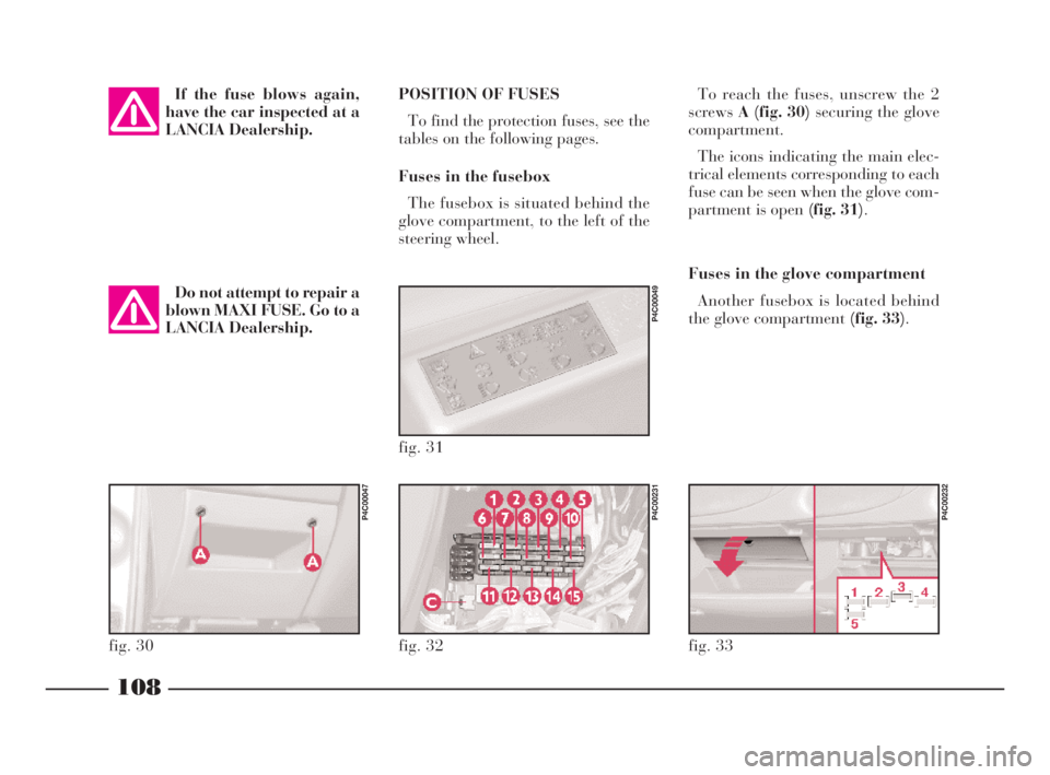
POSITION OF FUSES
To find the protection fuses, see the
tables on the following pages.
Fuses in the fusebox
The fusebox is situated behind the
glove compartment, to the left of the
steering wheel.To reach the fuses, unscrew the 2
screwsA (fig. 30) securing the glove
compartment.
The icons indicating the main elec-
trical elements corresponding to each
fuse can be seen when the glove com-
partment is open (fig. 31).
Fuses in the glove compartment
Another fusebox is located behind
the glove compartment (fig. 33).
fig. 32
P4C00231
fig. 33
P4C00232
fig. 31
P4C00049
fig. 30
P4C00047
If the fuse blows again,
have the car inspected at a
LANCIA Dealership.
Do not attempt to repair a
blown MAXI FUSE. Go to a
LANCIA Dealership.
4C090-119 ING 13-03-2008 12:51 Pagina 108
Page 112 of 191
109
fG
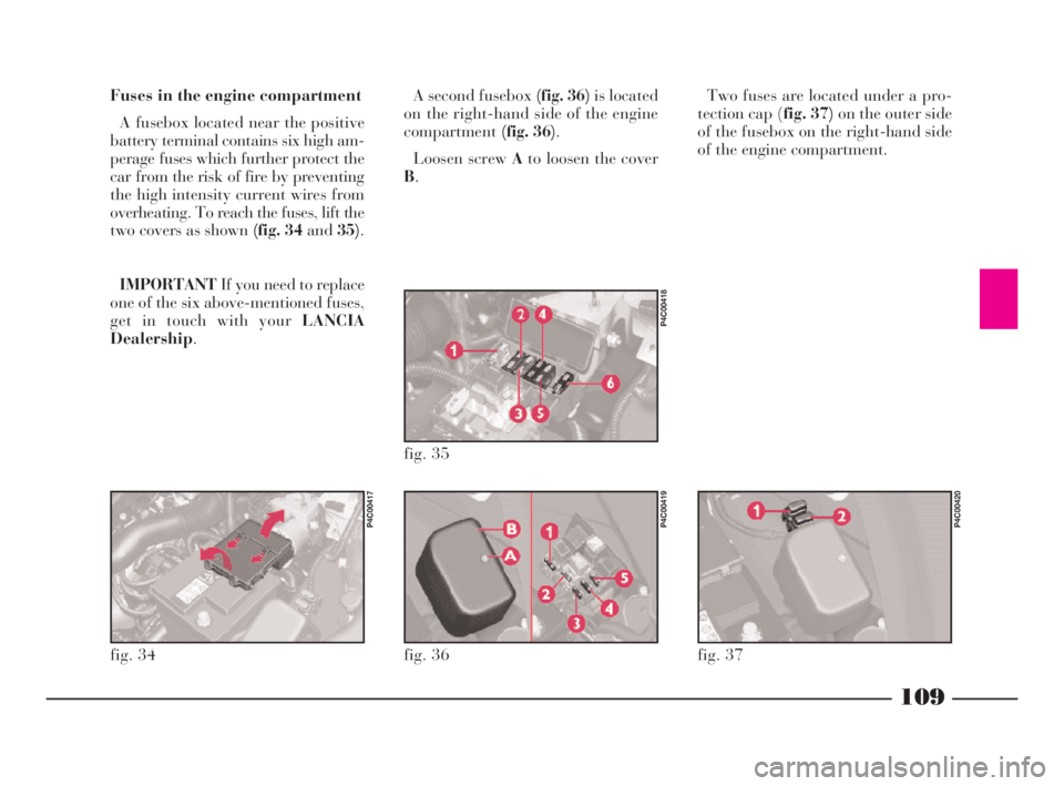
Fuses in the engine compartment
A fusebox located near the positive
battery terminal contains six high am-
perage fuses which further protect the
car from the risk of fire by preventing
the high intensity current wires from
overheating. To reach the fuses, lift the
two covers as shown (fig. 34 and35).
IMPORTANTIf you need to replace
one of the six above-mentioned fuses,
get in touch with your LANCIA
Dealership.A second fusebox (fig. 36)is located
on the right-hand side of the engine
compartment(fig. 36).
Loosen screw Ato loosen the cover
B.Two fuses are located under a pro-
tection cap (fig. 37)on the outer side
of the fusebox on the right-hand side
of the engine compartment.
fig. 34
P4C00417
fig. 36
P4C00419
fig. 37
P4C00420
fig. 35
P4C00418
4C090-119 ING 13-03-2008 12:51 Pagina 109
Page 113 of 191
110
fG
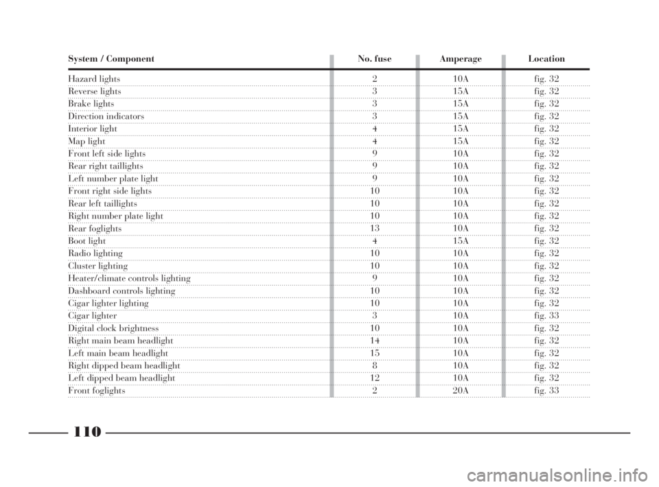
System / Component No. fuse Amperage Location
Hazard lights
Reverse lights
Brake lights
Direction indicators
Interior light
Map light
Front left side lights
Rear right taillights
Left number plate light
Front right side lights
Rear left taillights
Right number plate light
Rear foglights
Boot light
Radio lighting
Cluster lighting
Heater/climate controls lighting
Dashboard controls lighting
Cigar lighter lighting
Cigar lighter
Digital clock brightness
Right main beam headlight
Left main beam headlight
Right dipped beam headlight
Left dipped beam headlight
Front foglights
2 10A fig. 32
3 15A fig. 32
3 15A fig. 32
3 15A fig. 32
4 15A fig. 32
4 15A fig. 32
9 10A fig. 32
9 10A fig. 32
9 10A fig. 32
10 10A fig. 32
10 10A fig. 32
10 10A fig. 32
13 10A fig. 32
4 15A fig. 32
10 10A fig. 32
10 10A fig. 32
9 10A fig. 32
10 10A fig. 32
10 10A fig. 32
3 10A fig. 33
10 10A fig. 32
14 10A fig. 32
15 10A fig. 32
8 10A fig. 32
12 10A fig. 32
2 20A fig. 33
4C090-119 ING 13-03-2008 12:51 Pagina 110
Page 114 of 191
111
fG
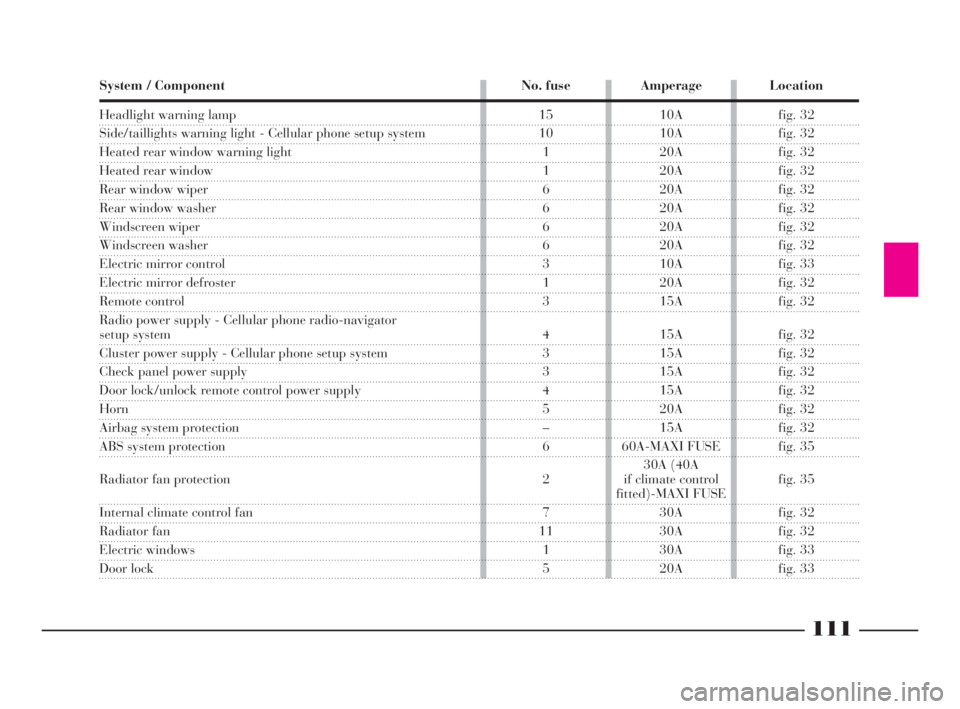
Headlight warning lamp
Side/taillights warning light - Cellular phone setup system
Heated rear window warning light
Heated rear window
Rear window wiper
Rear window washer
Windscreen wiper
Windscreen washer
Electric mirror control
Electric mirror defroster
Remote control
Radio power supply - Cellular phone radio-navigator
setup system
Cluster power supply - Cellular phone setup system
Check panel power supply
Door lock/unlock remote control power supply
Horn
Airbag system protection
ABS system protection
Radiator fan protection
Internal climate control fan
Radiator fan
Electric windows
Door lock System / Component No. fuse Amperage Location
15 10A fig. 32
10 10A fig. 32
1 20A fig. 32
1 20A fig. 32
6 20A fig. 32
6 20A fig. 32
6 20A fig. 32
6 20A fig. 32
3 10A fig. 33
1 20A fig. 32
3 15A fig. 32
4 15A fig. 32
3 15A fig. 32
3 15A fig. 32
4 15A fig. 32
5 20A fig. 32
– 15A fig. 32
6 60A-MAXI FUSE fig. 35
30A (40A
2 if climate control fig. 35
fitted)-MAXI FUSE
7 30A fig. 32
11 30A fig. 32
1 30A fig. 33
5 20A fig. 33
4C090-119 ING 13-03-2008 12:51 Pagina 111
Page 115 of 191
112
fG
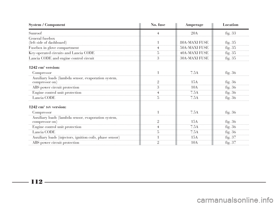
System / Component No. fuse Amperage Location
Sunroof
General fusebox
(left side of dashboard)
Fusebox in glove compartment
Key-operated circuits and Lancia CODE
Lancia CODE and engine control circuit
1242 cm
3version:
Compressor
Auxiliary loads (lambda sensor, evaporation system,
compressor on)
ABS power circuit protection
Engine control unit protection
Lancia CODE
1242 cm
316Vversion:
Compressor
Auxiliary loads (lambda sensor, evaporation system,
compressor on)
Engine control unit protection
Lancia CODE
Auxiliary loads (injectors, ignition coils, phase sensor)
ABS power circuit protection4 20A fig. 33
1 80A-MAXI FUSE fig. 35
4 50A-MAXI FUSE fig. 35
5 40A-MAXI FUSE fig. 35
3 30A-MAXI FUSE fig. 35
1 7.5A fig. 36
2 15A fig. 36
3 10A fig. 36
4 7.5A fig. 36
5 7.5A fig. 36
1 7.5A fig. 36
2 15A fig. 36
4 7.5A fig. 36
5 7.5A fig. 36
1 15A fig. 37
2 10A fig. 37
les
00
ed
az-
ve
4C090-119 ING 13-03-2008 12:51 Pagina 112
Page 116 of 191
113
fG
RECHARGING THE BATTERY
You are recommended to recharge
the battery slowly for a period of ap-
proximately 24 hours at a very low
amperage.
Extensive charging could damage
the battery.
Proceed as follows:
1)Disconnect the electrical system
terminals from the battery posts.
2)Connect the charger cables to the
battery terminals.
3)Turn on the charger.
4)When you have finished, turn the
charger off before disconnecting the
battery.
5)Reconnect the terminals to the
battery posts. Make sure the polarity
is correct (connect the negative post
last).IF THE BATTERY
IS FLAT
First of all, read the “Car mainte-
nance” section for the steps to be
taken to avoid the battery running
down and to ensure it has a long life.
JUMP STARTING
See “Jump starting” in this section.The liquid in the battery
is poisonous and corrosive.
Do not let it touch the skin
or eyes. Recharging the battery
should be done in a well-venti-
lated area and away from naked
flames or possible sources of
sparks: explosion and fire risk.
Never try to charge a
frozen battery: first let it
thaw out, otherwise it
could explode.
If the battery has frozen, check
that the internal elements are not
broken (risk of short circuit) and
that the casing is not cracked
causing the acid to leak out. This
acid is poisonous and corrosive.
Under no circumstances
should a battery charger
be used to start the engine:
it could damage the electronic sys-
tems and in particular the control
units governing ignition and fuel
feed.
4C090-119 ING 13-03-2008 12:51 Pagina 113
Page 117 of 191

114
fG
WITH A SHOP JACK
Front end
The car may only be raised by plac-
ing the jack arm under the transaxle,
with a block of wood or rubber as il-
lustrated in (fig. 38).IF THE CAR NEEDS
TO BE RAISED
WITH THE JACK
See “If a tyre is punctured”, in this
section.
The jack should only be
used to change a wheel on
the vehicle with which it is
supplied or on vehicles of the same
model. All other uses, for example
raising other vehicles, must be ex-
cluded. Under no circumstances
use the jack to carry out repairs
under the vehicle.
If the jack is not used
correctly, the raised vehi-
cle may fall. Do not use the
jack to lift weights above that in-
dicated on the label attached to the
jack itself.
It must be remembered that:
– the jack does not require adjust-
ments;
– the jack cannot be repaired. If it
breaks, it must be changed with an-
other new jack;
– only the jack handle described in
the chapter “If a tyre is punctured”
can be fitted onto the jack.
fig. 38
P4C00393
4C090-119 ING 13-03-2008 12:51 Pagina 114
Page 118 of 191

115
fG
Rear end
The car may only be raised by plac-
ing the jack arm at the two anchoring
points of the rear bumper, and posi-
tioning a flat piece of wood as illus-
trated in (fig. 39)(dimensions given
in mm).Lifting at the sides
The car may only be
raised at the sides if the
hydraulic jack arm is fit-
ted with a special bracket.
Alternatively, a special piece of wood
can be used with a groove that fits on
to the fin on the side member
(fig. 40).
fig. 39
P4C00138
fig. 40
P4C00139
ARM-TYPE HOIST
The car must be raised by placing
the ends of the arms in the areas il-
lustrated in (fig. 41).
fig. 41
P4C00410
4C090-119 ING 13-03-2008 12:51 Pagina 115
Page 119 of 191

116
fG
IF THE CAR NEEDS
TO BE TOWED
The tow ring is supplied as standard
with the car.
How to attach the tow ring to the
car:
1)Take the tow ring out of its sup-
port, located under the boot carpeting.
2)Remove the flap in the bumper,
using a screwdriver to pry it off.
3)Screw ring A (fig. 42)onto the
threaded pin B (fig. 43)orC (fig. 44)
which can be seen when the cover is
removed.When towing the car, you
must adhere to the specific
traffic regulations regard-
ing the tow hitch and how to tow
on the road.
B- front anchorage point (fig. 43).
C- rear anchorage point (fig. 44).
fig. 42
P4C00135
fig. 43
P4C00412
fig. 44
P4C00003
4C090-119 ING 13-03-2008 12:51 Pagina 116
Page 120 of 191

117
fG
While the car is being
towed with the engine off,
remember that the brake
pedal and steering will require
more effort as you no longer have
the benefit of the brake booster
and power steering. Do not use
flexible cables to tow. Avoid jerk-
ing. Whilst towing, ensure that the
coupling to the car does not dam-
age the surrounding components.Do not extract the igni-
tion key during towing;
leave it at MAR, to prevent
the steering lock engaging and,
provided the electrical system is
not damaged, keep the brake lights
and direction indicators working.
When the ignition key is re-
moved, the steering lock will cut in
thus preventing the steering wheel
from being turned.IF AN ACCIDENT
OCCURS
– It is important to keep calm.
– If you are not directly involved,
stop at least ten metres away from the
accident.
– If you are on a motorway do not
obstruct the emergency lane with your
car.
– Turn off the engine and turn on
the hazard lights.
– At night, illuminate the scene of
the accident with your headlights.
– Act carefully, you must not risk
being run over.
– Mark the accident by putting the
red triangle at the regulatory distance
from the car where it can be clearly
seen.
– If the doors are jammed, do not try
to leave the car by breaking the glass
of the windscreen as the glass is strat-
ified. Side windows and the rear win-
dow can be broken more easily.
4C090-119 ING 13-03-2008 12:51 Pagina 117