headlight Lancia Ypsilon 2011 Owner handbook (in English)
[x] Cancel search | Manufacturer: LANCIA, Model Year: 2011, Model line: Ypsilon, Model: Lancia Ypsilon 2011Pages: 299, PDF Size: 13.35 MB
Page 80 of 299

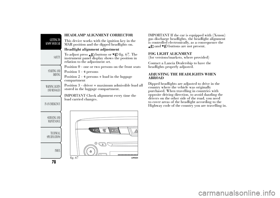
HEADLAMP ALIGNMENT CORRECTOR
This device works with the ignition key in the
MAR position and the dipped headlights on.
Headlight alignment adjustment
To adjust press
buttons or
fig. 67. The
instrument panel display shows the position in
relation to the adjustment set.
Position 0 - one or two persons on the front seats
Position1-4persons
Position2-4persons + load in the luggage
compartment
Position 3 - driver + maximum admissible load all
stored in the luggage compartment.
IMPORTANT Check alignment every time the
load carried changes.IMPORTANT If the car is equipped with (Xenon)
gas discharge headlights, the headlight alignment
is controlled electronically, as a consequence the
and
buttons are not present.
FOG LIGHT ALIGNMENT
(for versions/markets, where provided)
Contact a Lancia Dealership to have the
headlights properly adjusted.
ADJUSTING THE HEADLIGHTS WHEN
ABROAD
Dipped headlights are adjusted to drive in the
country where the vehicle was originally
purchased. When travelling in countries with
opposite driving direction, to avoid dazzling the
drivers on the other side of the road, you need
to cover areas of the headlight according to the
Highway code of the country you are travelling in.
fig. 67
L0F0224
78GETTING TO
KNOW YOUR CAR
SAFETY
STARTING
AND
DRIVING
WARNING LIGHTS
AND MESSAGES
IN AN EMERGENCY
SERVICING AND
MAINTENANCE
TECHNICAL
SPECIFICATIONS
INDEX
Page 139 of 299

Electrical devices
Only use electrical devices for the time needed.
The heated rear window, additional headlights,
windscreen wipers and heater fan need a
considerable amount of energy, therefore
increasing fuel consumption (by up to 25% in the
urban cycle).
Climate control system
The use of the climate control system leads to
higher fuel consumption. If the temperature
outside permits, try to use ventilation only.
Devices for aerodynamic control
The use of non-certified devices for aerodynamic
control may adversely affect air drag and fuel
consumption.
DRIVING STYLE
Starting
Do not warm the engine with the car at a
standstill or at idle or high speed: under these
conditions the engine warms up much more
slowly, increasing consumption and emissions. It is
therefore advisable to move off immediately,
slowly, avoiding high speeds: in this way
the engine will warm up more quickly.Unnecessary actions
Avoid revving up when at traffic lights or before
stopping the engine. This and also double
declutching is absolutely pointless on modern cars
and also increases consumption and pollution.
Gear selection
Use a higher gear as soon as traffic and road
conditions allow. Using a low gear for faster
acceleration will increase consumption.
In the same way improper use of a high gear
increases consumption, emissions and engine wear.
Maximum speed
Fuel consumption considerably increases as speed
increases. Maintain a constant speed, avoiding
unnecessary braking and acceleration, which cost
in terms of both fuel and emissions.
Acceleration
Sudden acceleration has a very negative effect on
fuel consumption and emissions: accelerate
gradually.
137GETTING TO KNOW
YOUR CAR
SAFETYSTARTING AND
DRIVINGWARNING LIGHTS
AND
MESSAGES
IN AN
EMERGENCY
SERVICING AND
MAINTENANCE
TECHNICAL
SPECIFICATIONS
INDEX
Page 170 of 299

CHANGING A BULBGENERAL INSTRUCTIONS
❒Before changing a bulb check the contacts for
oxidation;
❒Burnt bulbs must be replaced by others of the
same type and power;
❒after replacing a headlight bulb, always check
its alignment;
❒when a light is not working, check that the
corresponding fuse is intact before changing
a bulb. For the location of fuses, refer to the
paragraph “If a fuse blows” in this section;
WARNING
Modifications or repairs to the
electric system that
are not carried
out properly or do not take the system
technical specifications into account can
cause malfunctions leading to the risk of
fire.
WARNING
Halogen bulbs contain pressurised
gas, in the
case of breakage they may
burst.
Halogen bulbs must be handled
holding the metallic part only.
Touching the transparent part of the
bulb with your fingers may reduce the
intensity of the emitted light and even reduce
the lifespan of the bulb. In case of accidental
contact, wipe the bulb with a cloth moistened
with alcohol and let the bulb dry.If possible, we recommend that you
have bulbs replaced at a Lancia
Dealership. The correct operation and
aiming of the outer lights are absolutely
essential for the safety of the car and of
compliance with law.Due to the high supply voltage, Xenon
gas-discharge bulbs (for versions/
markets, where provided) must only be
replaced by a specialist technician: danger of
death! Contact a Lancia Dealership.
168
GETTING TO KNOW
YOUR CAR
SAFETY
STARTING AND
DRIVING
WARNING LIGHTS
AND MESSAGESIN AN EMERGENCYSERVICING AND
MAINTENANCE
TECHNICAL
SPECIFICA
TIONS
INDEX
Page 171 of 299

IMPORTANT When the weather is cold or damp
or after heavy rain or washing, the surface of
headlights or rear lights, may steam up and/or
form drops of condensation on the inside. This is a
natural phenomenon due to the difference in
temperature and humidity between the inside and
the outside of the glass which does not indicate a
fault and does not compromise the normal
operation of lighting devices. The mist disappears
quickly when the lights are turned on, starting
from the centre of the diffuser, extending
progressively towards the edges.
169GETTING TO KNOW
YOUR CAR
SAFETY
STARTING AND
DRIVING
WARNING LIGHTS
AND MESSAGESIN AN EMERGENCYSERVICING AND
MAINTENANCE
TECHNICAL
SPECIFICA
TIONS
INDEX
Page 173 of 299

BulbsUse Type Power Re. Figure
Dipped headlights\Main Beam Headlights H4 55W D
Dipped headlamps with gas discharge
bulbs (Xenon) (for versions/markets where
provided)D1S 35W F
Front side lights W5W 5W A
Daytime Running Lights (DRL) W21W 21W B
Rear side lights LEDs - -
Front direction indicators PY24W 24W B
Side direction indicators W5W 5W A
Rear direction indicators PY21W 21W B
Stop W16W 16W B
3rd brake light LEDs - -
Fog light H1 55W E
Reverse P21W 21W B
Rear fog lamp P21W 21W B
Number plate W5W 5W C
Front roof light C5W 5W C
Luggage compartment roof light W5W 5W A
Glove compartment light C5W 5W C
171GETTING TO KNOW
YOUR CAR
SAFETY
STARTING AND
DRIVING
WARNING LIGHTS
AND MESSAGESIN AN EMERGENCYSERVICING AND
MAINTENANCE
TECHNICAL
SPECIFICA
TIONS
INDEX
Page 174 of 299

REPLACING EXTERIOR BULBSFor the type of bulb and power rating, see
“Changing a bulb".
FRONT LIGHT UNITS
These contain the bulbs for the side lights/day
lights (DRL), dipped beams, main beams and
direction indicators. The bulbs are arranged
as follows fig. 125:ASide lights/day lights and main beam headlightsBDipped beam headlightsCDirection indicatorsSIDE LIGHTS/DAY LIGHTS (DRL)
To change the bulb, proceed as follows:
❒remove cover A fig. 125;
❒remove snap-fitted bulb holder B fig. 126,
remove the bulb C and replace it;
❒refit the new bulb then reinsert the bulb holder
B in its housing;
❒then refit the cover A fig. 125.fig. 125
L0F0033
fig. 126
L0F0069
172
GETTING TO KNOW
YOUR CAR
SAFETY
STARTING AND
DRIVING
WARNING LIGHTS
AND MESSAGESIN AN EMERGENCYSERVICING AND
MAINTENANCE
TECHNICAL
SPECIFICA
TIONS
INDEX
Page 175 of 299

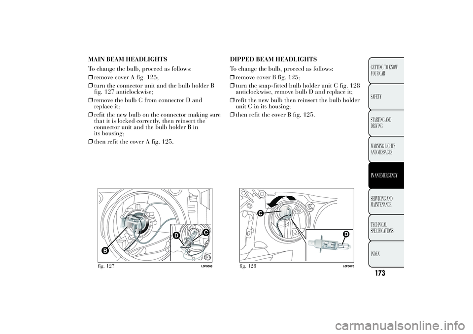
MAIN BEAM HEADLIGHTS
To change the bulb, proceed as follows:
❒remove cover A fig. 125;
❒turn the connector unit and the bulb holder B
fig. 127 anticlockwise;
❒remove the bulb C from connector D and
replace it;
❒refit the new bulb on the connector making sure
that it is locked correctly, then reinsert the
connector unit and the bulb holder B in
its housing;
❒then refit the cover A fig. 125.DIPPED BEAM HEADLIGHTS
To change the bulb, proceed as follows:
❒remove cover B fig. 125;
❒turn the snap-fitted bulb holder unit C fig. 128
anticlockwise, remove bulb D and replace it;
❒refit the new bulb then reinsert the bulb holder
unit C in its housing;
❒then refit the cover B fig. 125.
fig. 127
L0F0068
fig. 128
L0F0070
173GETTING TO KNOW
YOUR CAR
SAFETY
STARTING AND
DRIVING
WARNING LIGHTS
AND MESSAGESIN AN EMERGENCYSERVICING AND
MAINTENANCE
TECHNICAL
SPECIFICA
TIONS
INDEX
Page 190 of 299

FUSE SUMMARY TABLEEngine compartment fuse box FUSE AMPS
BCM F01 60
RDU F02 50
Ignition switch F03 20
BSM1 (pump) F04 40
EPS F05 70
Engine single speed cooling fan (heated engines) F06 20
Engine dual speed cooling fan solenoid valve/Engine
cooling fan low speed (conditioned engines)F06 30
Engine cooling electric fan high speed F07 40
Fog lights F08 30
Headlamp washer pump F09 20
Horns F10 15
Engine management system (secondary loads) F11 10
Main beam headlights F14 15
Sunroof motor F15 20
+15 ECM/coil T10 F16 7,5
ECM main loads (versions 0.9 TwinAir 85 HP/
F17 10
'+30 ECM/coil T09 F18 5
Fuel pump F19 15
188
GETTING TO KNOW
YOUR CAR
SAFETY
STARTING AND
DRIVING
WARNING LIGHTS
AND MESSAGESIN AN EMERGENCYSERVICING AND
MAINTENANCE
TECHNICAL
SPECIFICA
TIONS
INDEX
1.2 8V 69 HP)
Page 204 of 299

PERIODIC CHECKSEvery 1,000 km or before long journeys, check
and, if necessary, restore:
❒engine coolant, brake fluid and windscreen
washer fluid level;
❒tyre inflation pressure and condition;
❒operation of lighting system (headlights,
direction indicators, hazard warning lights,
etc.);
❒operation of screen washer/wiper system and
positioning/wear of windscreen/rear window
wiper blades.
Every 3,000 km, check and top up, if required,
the engine oil level.
HEAVY-DUTY USE OF THE CARIf the car is used mainly under one of the
following conditions:
❒towing a trailer or caravan;
❒dusty roads;
❒short, repeated journeys (less than 7-8 km) at
sub-zero outside temperatures;
❒engine often idling or driving long distances at
low speeds or long periods of idleness;
you should perform the following inspections more
frequently than shown on the Scheduled Servicing
Plan:
❒check front disc brake pad conditions and wear;
❒check cleanliness of bonnet and boot locks,
cleanliness and lubrication of linkage;
❒visually inspect conditions of: engine, gearbox,
transmission, pipes and hoses (exhaust - fuel
system - brakes) and rubber elements (boots -
sleeves - bushes - etc.);
❒check battery charge and battery fluid level
(electrolyte);
❒visually inspect condition of the accessory drive
belts;
❒check and, if necessary, change engine oil and
replace oil filter;
❒check and, if necessary, replace pollen filter;
❒check and, if necessary, replace air cleaner.
202
GETTING TO KNOW
YOUR CAR
SAFETY
STARTING AND
DRIVING
WARNING LIGHTS
AND MESSAGES
IN AN EMERGENCYSERVICING AND
MAINTENANCE
TECHNICAL
SPECIFICA
TIONS
INDEX
Page 217 of 299

Rear window washer
The rear window washer jets are fixed. The nozzle
holder is on the rear window fig. 165.HEADLIGHT WASHERS
(for versions/markets, where provided)
They are located inside the front bumper fig. 166.
They are activated when the dipped beam and/or
main beam headlights are on and the windscreen
washer is activated.
Check the correct condition and cleanliness of
nozzles at regular intervals.
fig. 165
L0F0223
fig. 166
L0F0023
215GETTING TO KNOW
YOUR CAR
SAFETY
STARTING AND
DRIVING
WARNING LIGHTS
AND MESSAGES
IN AN EMERGENCYSERVICING AND
MAINTENANCETECHNICAL
SPECIFICA
TIONS
INDEX