Lancia Ypsilon 2018 Owner handbook (in English)
Manufacturer: LANCIA, Model Year: 2018, Model line: Ypsilon, Model: Lancia Ypsilon 2018Pages: 200, PDF Size: 4.53 MB
Page 111 of 200

REPLACING AN
EXTERNAL BULB
FRONT LIGHT CLUSTERS
These contain the bulbs for the daytime
running lights (DRL), side lights,
dipped/main beam headlights and
direction indicators.
The bulbs are arranged as follows fig.
83:
Daytime running lights (DRL)
Dipped/main beam headlights and
side lights
Direction indicators
Daytime running lights (DRL)
To replace the bulb, proceed as follows:
remove cover A fig. 83;
turn the snap-fitted bulb holder unit
B fig. 84 anticlockwise, remove bulb
C and replace it;
refit the new bulb then reinsert the
bulb holder B fig. 84 in its housing;
then refit the cover A fig. 83.
Side lights
To replace the bulb, proceed as follows:
remove cover B fig. 83;
remove snap-fitted bulb holder C fig.
85, remove the bulb D and replace it;
refit the new bulb then reinsert
the bulb holder unit C fig. 85 in
its housing;
then refit the cover B fig. 83.
Dipped/main beam headlights
To replace the bulb, proceed as follows:
remove the cover B fig. 83 and
then the snap-fitted bulb holder C fig.
86;
remove bulb D from the connector E
and replace it;
refit the new bulb on the connector
making sure that it is locked correctly,
then reinsert bulb holder C in its
housing;
then refit the cover B fig. 83.
Front direction indicators
To replace the bulb, proceed as follows:
turn the cover C fig. 83
anticlockwise, extract the bulb D fig. 87
from its housing and replace it;
83L0F0033C
84L0F0070C
85L0F0069C
86L0F0068C
109
Page 112 of 200

refit the bulb D in the housing E and
then fit the cover C fig. 83.
Side direction indicators
To replace the bulb, proceed as follows:
adjust the lens A fig. 89 to
compress in the internal catch B, then
pull the unit outwards;
turn the bulb holder C anticlockwise,
extract the bulb and replace it;
refit the bulb holder C in the lens and
turn it clockwise;
refit the cluster making sure that the
internal catch B clips into position.
Front fog lights
(for versions/markets, where provided)
To replace the bulb, proceed as follows:
steer the wheel completely, adjust
the tabs A fig. 89 and remove the
flap B;
adjust the clip C fig. 90 and
disconnect the electrical connector D;
remove the cover E by turning it
clockwise (see the word OFF and the
arrow on the cover);
release the catches F fig. 91
removing them outwards;
release the connector G fig. 92 and
replace the bulb H;
87L0F0071C
88L0F0209C
89L0F0205C
90L0F0206C
91L0F0207C
92L0F0208C
110
IN AN EMERGENCY
Page 113 of 200

refit the new lamp and carry out the
procedure described previously in
reverse.
REAR LIGHT CLUSTERS
These contain the bulbs for the side
lights, brake lights and direction
indicators. The reversing lights and rear
fog lights are located instead in the
rear bumper.
The bulbs are arranged as follows fig.
93:A- Direction indicators
B- Brake lights
Direction indicators/brake lights
Turn the bulb holder in directionO
(open) to replace the bulbs. After
replacing the bulb, turn the bulb holder
in directionC(close).
Side lights
These are LEDs. Contact a Lancia
Dealership for replacement.
THIRD BRAKE LIGHTS
These are located in the tailgate and
are LED lights. Contact a Lancia
Dealership for replacement.
REVERSING LIGHT/REAR FOG
LIGHT
To replace the bulb, proceed as follows:
working from inside the bumper,
turn the bulb holder unit A fig. 94 by a
1/4 turn;
extract the bulb and replace it;
refit the new bulb then reinsert the
bulb holder in its housing.
NUMBER PLATE LIGHTS
To replace the bulbs proceed as
follows:
remove lens A fig. 95;
turn the bulb holder B fig. 96
clockwise, extract the bulb C and
replace it; then refit the lens.
93L0F0034C
94L0F0219C
95L0F0259C
96L0F0214C
111
Page 114 of 200
WARNING
121)Modifications or repairs to the electric
system that are not carried out properly
or do not take the system technical
specifications into account can cause
malfunctions leading to the risk of fire.
122)Halogen bulbs contain pressurised
gas, in the case of breakage they may
burst causing glass fragments to be
projected outwards.
WARNING
51)Halogen bulbs must be handled
holding the metallic part only. Touching the
transparent part of the bulb with your
fingers may reduce the intensity of the
emitted light and even reduce the lifespan
of the bulb. In the event of accidental
contact, wipe the bulb with a cloth
moistened with alcohol and let the bulb
dry.
52)If possible, we recommend that you
have bulbs replaced at a Lancia
Dealership. The correct operation and
direction of the external lights are
absolutely essential for the safety of the car
and of compliance with the law.
REPLACING FUSES
123) 124) 125) 126) 127) 128)
GENERAL
To facilitate fuse replacement, use the
pliers hooked inside the fuse box lid on
the dashboard left-hand side.
ENGINE COMPARTMENT
FUSE BOX
53)
This is located by the side of the
battery. To access the fuses, proceed
as follows:
move the cover A fig. 97, undo the
screw A fig. 98, release the tabs B
and pull the cover C upwards.The number identifying the electrical
component corresponding to each fuse
is shown on the cover. After replacing
the fuse, make sure that you have
closed cover C correctly on the
fusebox.
97L0F0170C
98L0F0094C
112
IN AN EMERGENCY
Page 115 of 200

DASHBOARD FUSE BOX
The control unit fig. 100 is located near
the left side of the steering column
and the fuses can be accessed easily
from the lower part of the dashboard.LUGGAGE
COMPARTMENT FUSE
BOX
The fuse box is located on the left side
of the luggage compartment,
underneath the side cover A fig. 101.
The fuses are located in the fuse box
shown in fig. 102.
99L0F0433C100L0F0248C
101L0F0128C
102L0F0212C
113
Page 116 of 200
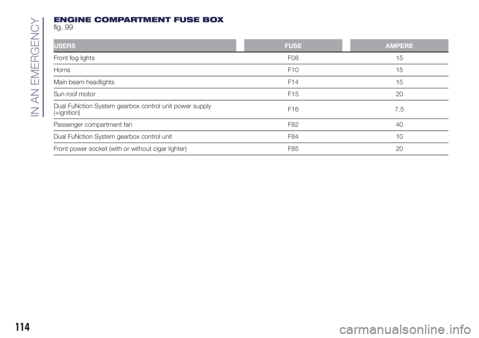
ENGINE COMPARTMENT FUSE BOX
fig. 99
USERSFUSE AMPERE
Front fog lights F08 15
HornsF10 15
Main beam headlights F14 15
Sun roof motor F15 20
Dual FuNction System gearbox control unit power supply
(+ignition)F16 7.5
Passenger compartment fan F82 40
Dual FuNction System gearbox control unit F84 10
Front power socket (with or without cigar lighter) F85 20
114
IN AN EMERGENCY
Page 117 of 200
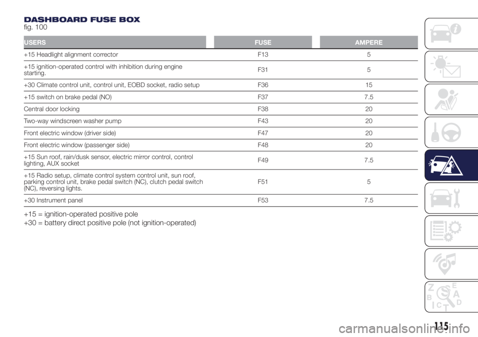
DASHBOARD FUSE BOX
fig. 100
USERSFUSE AMPERE
+15 Headlight alignment corrector F13 5
+15 ignition-operated control with inhibition during engine
starting.F31 5
+30 Climate control unit, control unit, EOBD socket, radio setup F36 15
+15 switch on brake pedal (NO) F37 7.5
Central door locking F38 20
Two-way windscreen washer pump F43 20
Front electric window (driver side) F47 20
Front electric window (passenger side) F48 20
+15 Sun roof, rain/dusk sensor, electric mirror control, control
lighting, AUX socketF49 7.5
+15 Radio setup, climate control system control unit, sun roof,
parking control unit, brake pedal switch (NC), clutch pedal switch
(NC), reversing lights.F51 5
+30 Instrument panel F53 7.5
+15 = ignition-operated positive pole
+30 = battery direct positive pole (not ignition-operated)
115
Page 118 of 200
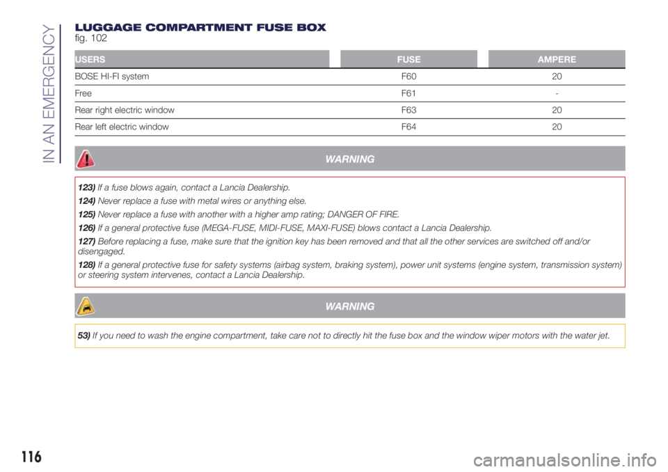
LUGGAGE COMPARTMENT FUSE BOX
fig. 102
USERSFUSE AMPERE
BOSE HI-FI system F60 20
FreeF61 -
Rear right electric window F63 20
Rear left electric window F64 20
WARNING
123)If a fuse blows again, contact a Lancia Dealership.
124)Never replace a fuse with metal wires or anything else.
125)Never replace a fuse with another with a higher amp rating; DANGER OF FIRE.
126)If a general protective fuse (MEGA-FUSE, MIDI-FUSE, MAXI-FUSE) blows contact a Lancia Dealership.
127)Before replacing a fuse, make sure that the ignition key has been removed and that all the other services are switched off and/or
disengaged.
128)If a general protective fuse for safety systems (airbag system, braking system), power unit systems (engine system, transmission system)
or steering system intervenes, contact a Lancia Dealership.
WARNING
53)If you need to wash the engine compartment, take care not to directly hit the fuse box and the window wiper motors with the water jet.
116
IN AN EMERGENCY
Page 119 of 200
REPLACING A
WHEEL
129) 130) 131) 132) 133) 134) 135)
54) 55)
JACK
Please note that:
the jack weight is 1,76 kg;
the jack requires no adjustment;
the jack cannot be repaired and in
the event of a fault it must be replaced
by another genuine one;
no tool other than its cranking
device may be fitted on the jack.
CHANGING PROCEDURE
To change a wheel, proceed as follows:
stop the car in a position that is
not dangerous for oncoming traffic
where you can change the wheel safely.
The ground must be flat and sufficiently
compact;
switch off the engine, pull up the
handbrake and engage the 1stgear or
reverse. Wear the reflective safety
jacket (compulsory by law) before
getting out of the car;
open the luggage compartment, pull
tab A fig. 103 and lift up the mat;
using the wrench A fig. 104 located
in the tool box, loosen the locking
device, take the tool box B and place it
close to the wheel to be replaced.
Then take the space-saver wheel C;
remove the snap-fitted hub cap. On
vehicles with 15” rims and cosmetic
hub caps, use extractor B fig. 105
contained in the Owner Handbook
casing to assist removal. Hold the
extractor B with two fingers, insert the
tab between tyre and hub cap (A)
and pull towards yourself,
perpendicularly to the wheel;
for versions with alloy rims, remove
the press-fitted hub cap;
take tool A and undo the fastening
bolts by approximately one turn, as
shown in fig. 106 (e.g. in case of alloy
rims);
for versions with alloy rims, shake
the car to facilitate detachment of
the rim from the wheel hub;
position the jack under the car, near
the wheel to be changed;
103L0F0099C
104L0F0183C
105L0F0435C
117
Page 120 of 200

operate the device A fig. 107 to
extend the jack until the top part B fig.
108 fits correctly into the side member
C (next to the mark
on the side
member);
alert any bystander that the car is
about to be raised; all persons should
be kept away from the car and nobody
must touch it until it has been lowered;
fit handle D fig. 107 into the housing
in device A, operate the jack and raise
the vehicle until the wheel is a few
centimetres from the ground;
loosen the bolts completely and
remove the wheel to be replaced;
make sure the contact surfaces
between space-saver wheel and hub
are clean so that the fastening bolts will
not come loose;
fit the space-saver wheel by
inserting the first bolt for two threads
into the hole closest to the valve;
take the wrench A fig. 106 and fully
tighten the fixing bolts;
operate the jack handle D to lower
the car. Then extract the jack;
use the wrench A provided to fully
tighten the bolts in a criss-cross fashion
as per the numerical sequence
illustrated in fig. 109;
when replacing a wheel with alloy
rim it is advisable to place it upside
down in the boot with the cosmetic part
facing upwards.
Restore the standard wheel as soon as
possible, because, once placed in the
associated compartment, the luggage
compartment load platform is rendered
uneven as the standard wheel is larger
than the space-saver wheel.
REFITTING THE
STANDARD WHEEL
Following the procedure described
previously, raise the vehicle and remove
the space-saver wheel.
Versions with steel wheels
Proceed as follows:
make sure the contact surfaces
between standard wheel and hub are
clean so that the fastening bolts will not
come loose;
106L0F0179C
107L0F0025C
108L0F0024C
109L0F0182C
118
IN AN EMERGENCY