engine LAND ROVER DEFENDER 1999 Manual PDF
[x] Cancel search | Manufacturer: LAND ROVER, Model Year: 1999, Model line: DEFENDER, Model: LAND ROVER DEFENDER 1999Pages: 667, PDF Size: 8.76 MB
Page 124 of 667

ENGINE
1
ADJUSTMENT ENGINE OIL PRESSURE CHECK
Service repair no - 12.90.09.01
Check
1.Remove oil pressure switch.See Repair.
2.Connect pressure check kitLRT-12-052C
adaptor and gauge to oil pressure switch
position on oil cooler.
3.Check and if necessary, top-up engine oil.
4.Run engine at idle speed and check that oil
pressure is within limits given.
5.Switch off ignition.
6.Remove oil pressure check kitLRT-12-052C.
7.Clean oil spillage.
8.Fit oil pressure switch.See Repair.
Adjust
1.If engine oil pressure is not within specified
limits, check condition of oil pump and/or main
and connecting rod bearings.
ProCarManuals.com
Page 126 of 667

ENGINE
1
REPAIR CAMSHAFT
Service repair no - 12.13.02
Remove
1.Remove cylinder head gasket.See this
Section.
2.Note the gasket thickness indicator and ensure
the same thickness gasket is used on refitment
of cylinder head.
3.Disconnect multiplug from injector units and
remove harness from camshaft carrier.
4.Remove and discard multiplug’O’ring.
5.Loosen lock nuts and fully retract rocker
adjusting screws.
6.Progressively loosen then remove and discard 6
bolts securing rocker shaft, remove shaft.
7.Using sequence shown, progressively loosen
then remove 13 bolts securing camshaft carrier
to cylinder head.
8.Gently tap the camshaft carrier upwards to break
the sealant bond and remove carrier noting it is
located by 2 dowels.
9.Remove camshaft.
10.Remove and discard camshaft rear oil seal.
11.Remove and discard lock nuts and rocker
adjusting screws.
12.Check bearing surfaces in cylinder head and
camshaft carrier for signs of scoring and wear.
ProCarManuals.com
Page 127 of 667
12ENGINE
2
REPAIR
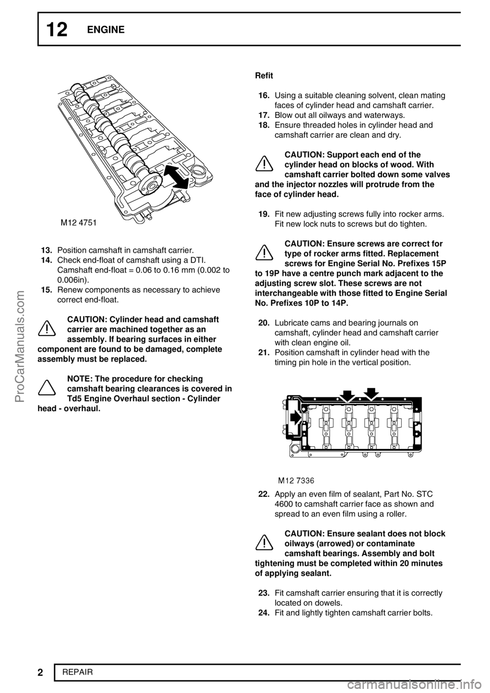
13.Position camshaft in camshaft carrier.
14.Check end-float of camshaft using a DTI.
Camshaft end-float = 0.06 to 0.16 mm (0.002 to
0.006in).
15.Renew components as necessary to achieve
correct end-float.
CAUTION: Cylinder head and camshaft
carrier are machined together as an
assembly. If bearing surfaces in either
component are found to be damaged, complete
assembly must be replaced.
NOTE: The procedure for checking
camshaft bearing clearances is covered in
Td5 Engine Overhaul section - Cylinder
head - overhaul.Refit
16.Using a suitable cleaning solvent, clean mating
faces of cylinder head and camshaft carrier.
17.Blow out all oilways and waterways.
18.Ensure threaded holes in cylinder head and
camshaft carrier are clean and dry.
CAUTION: Support each end of the
cylinder head on blocks of wood. With
camshaft carrier bolted down some valves
and the injector nozzles will protrude from the
face of cylinder head.
19.Fit new adjusting screws fully into rocker arms.
Fit new lock nuts to screws but do tighten.
CAUTION: Ensure screws are correct for
type of rocker arms fitted. Replacement
screws for Engine Serial No. Prefixes 15P
to 19P have a centre punch mark adjacent to the
adjusting screw slot. These screws are not
interchangeable with those fitted to Engine Serial
No. Prefixes 10P to 14P.
20.Lubricate cams and bearing journals on
camshaft, cylinder head and camshaft carrier
with clean engine oil.
21.Position camshaft in cylinder head with the
timing pin hole in the vertical position.
22.Apply an even film of sealant, Part No. STC
4600 to camshaft carrier face as shown and
spread to an even film using a roller.
CAUTION: Ensure sealant does not block
oilways (arrowed) or contaminate
camshaft bearings. Assembly and bolt
tightening must be completed within 20 minutes
of applying sealant.
23.Fit camshaft carrier ensuring that it is correctly
located on dowels.
24.Fit and lightly tighten camshaft carrier bolts.
ProCarManuals.com
Page 128 of 667
ENGINE
3
REPAIR
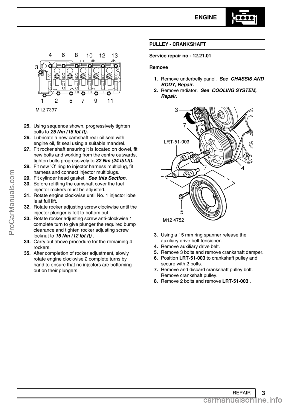
25.Using sequence shown, progressively tighten
bolts to25 Nm (18 lbf.ft).
26.Lubricate a new camshaft rear oil seal with
engine oil, fit seal using a suitable mandrel.
27.Fit rocker shaft ensuring it is located on dowel, fit
new bolts and working from the centre outwards,
tighten bolts progressively to32 Nm (24 lbf.ft).
28.Fit new’O’ring to injector harness multiplug, fit
harness and connect injector multiplugs.
29.Fit cylinder head gasket.See this Section.
30.Before refitting the camshaft cover the fuel
injector rockers must be adjusted.
31.Rotate engine clockwise until No. 1 injector lobe
is at full lift.
32.Rotate rocker adjusting screw clockwise until the
injector plunger is felt to bottom out.
33.Rotate rocker adjusting screw anti-clockwise 1
complete turn to give plunger the required bump
clearance and tighten rocker adjusting screw
locknut to16 Nm (12 lbf.ft).
34.Carry out above procedure for the remaining 4
rockers.
35.After completion of rocker adjustment, slowly
rotate engine clockwise 2 complete turns by
hand to ensure that no injectors are bottoming
out on their plungers.PULLEY - CRANKSHAFT
Service repair no - 12.21.01
Remove
1.Remove underbelly panel.See CHASSIS AND
BODY, Repair.
2.Remove radiator.See COOLING SYSTEM,
Repair.
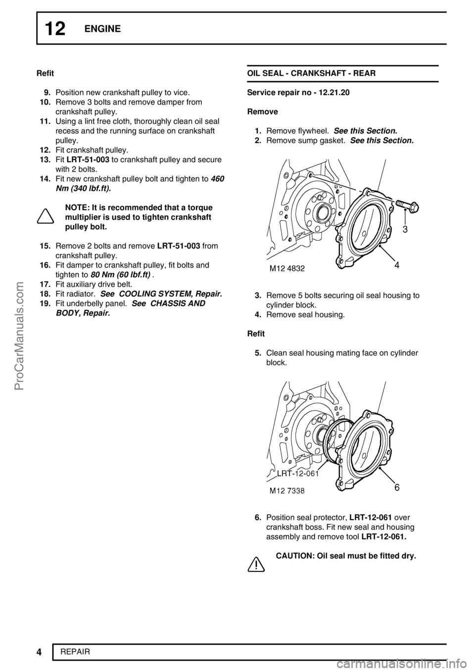
3.Using a 15 mm ring spanner release the
auxiliary drive belt tensioner.
4.Remove auxiliary drive belt.
5.Remove 3 bolts and remove crankshaft damper.
6.PositionLRT-51-003to crankshaft pulley and
secure with 2 bolts.
7.Remove and discard crankshaft pulley bolt.
Remove crankshaft pulley.
8.Remove 2 bolts and removeLRT-51-003.
ProCarManuals.com
Page 129 of 667
12ENGINE
4
REPAIR Refit
9.Position new crankshaft pulley to vice.
10.Remove 3 bolts and remove damper from
crankshaft pulley.
11.Using a lint free cloth, thoroughly clean oil seal
recess and the running surface on crankshaft
pulley.
12.Fit crankshaft pulley.
13.FitLRT-51-003to crankshaft pulley and secure
with 2 bolts.
14.Fit new crankshaft pulley bolt and tighten to460
Nm (340 lbf.ft).
NOTE: It is recommended that a torque
multiplier is used to tighten crankshaft
pulley bolt.
15.Remove 2 bolts and removeLRT-51-003from
crankshaft pulley.
16.Fit damper to crankshaft pulley, fit bolts and
tighten to80 Nm (60 lbf.ft).
17.Fit auxiliary drive belt.
18.Fit radiator.See COOLING SYSTEM, Repair.
19.Fit underbelly panel.See CHASSIS AND
BODY, Repair.OIL SEAL - CRANKSHAFT - REAR
Service repair no - 12.21.20
Remove
1.Remove flywheel.See this Section.
2.Remove sump gasket.See this Section.
3.Remove 5 bolts securing oil seal housing to
cylinder block.
4.Remove seal housing.
Refit
5.Clean seal housing mating face on cylinder
block.
6.Position seal protector,LRT-12-061over
crankshaft boss. Fit new seal and housing
assembly and remove toolLRT-12-061.
CAUTION: Oil seal must be fitted dry.
ProCarManuals.com
Page 130 of 667
ENGINE
5
REPAIR
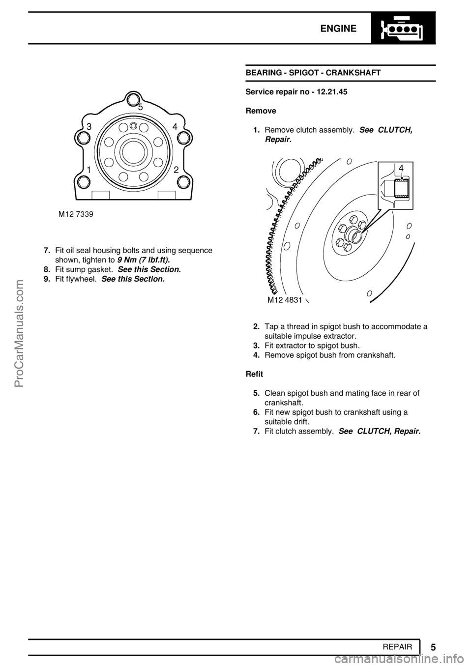
7.Fit oil seal housing bolts and using sequence
shown, tighten to9 Nm (7 lbf.ft).
8.Fit sump gasket.See this Section.
9.Fit flywheel.See this Section.BEARING - SPIGOT - CRANKSHAFT
Service repair no - 12.21.45
Remove
1.Remove clutch assembly.See CLUTCH,
Repair.
2.Tap a thread in spigot bush to accommodate a
suitable impulse extractor.
3.Fit extractor to spigot bush.
4.Remove spigot bush from crankshaft.
Refit
5.Clean spigot bush and mating face in rear of
crankshaft.
6.Fit new spigot bush to crankshaft using a
suitable drift.
7.Fit clutch assembly.See CLUTCH, Repair.
ProCarManuals.com
Page 131 of 667
12ENGINE
6
REPAIR GASKET - CYLINDER HEAD
Service repair no - 12.29.02
Remove
NOTE: The following procedures cover
engines fitted with or without an EGR
cooler. The EGR cooler is bolted to the
front of the cylinder head.
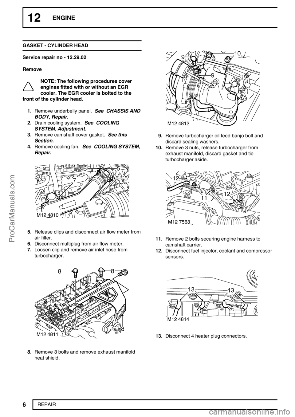
1.Remove underbelly panel.See CHASSIS AND
BODY, Repair.
2.Drain cooling system.See COOLING
SYSTEM, Adjustment.
3.Remove camshaft cover gasket.See this
Section.
4.Remove cooling fan.See COOLING SYSTEM,
Repair.
5.Release clips and disconnect air flow meter from
air filter.
6.Disconnect multiplug from air flow meter.
7.Loosen clip and remove air inlet hose from
turbocharger.
8.Remove 3 bolts and remove exhaust manifold
heat shield.
9.Remove turbocharger oil feed banjo bolt and
discard sealing washers.
10.Remove 3 nuts, release turbocharger from
exhaust manifold, discard gasket and tie
turbocharger aside.
11.Remove 2 bolts securing engine harness to
camshaft carrier.
12.Disconnect fuel injector, coolant and compressor
sensors.
13.Disconnect 4 heater plug connectors.
ProCarManuals.com
Page 132 of 667

ENGINE
7
REPAIR
14.Disconnect MAP sensor multiplug from inlet
manifold.
15.Position engine harness clear of inlet manifold.
16.Disconnect vacuum hose from EGR valve.
17.Loosen clip screw and disconnect air intake
hose from EGR valve.
18.Release 3 clips and disconnect coolant hoses
from fuel cooler.
19.Disconnect fuel hoses, tank to fuel cooler and
connector block on cylinder head.
CAUTION: Plug the connections.
20.Disconnect fuel hose from fuel cooler and secure
to connector block on cylinder head. This is to
prevent contamination of the fuel injection
system.
ProCarManuals.com
Page 133 of 667
12ENGINE
8
REPAIR
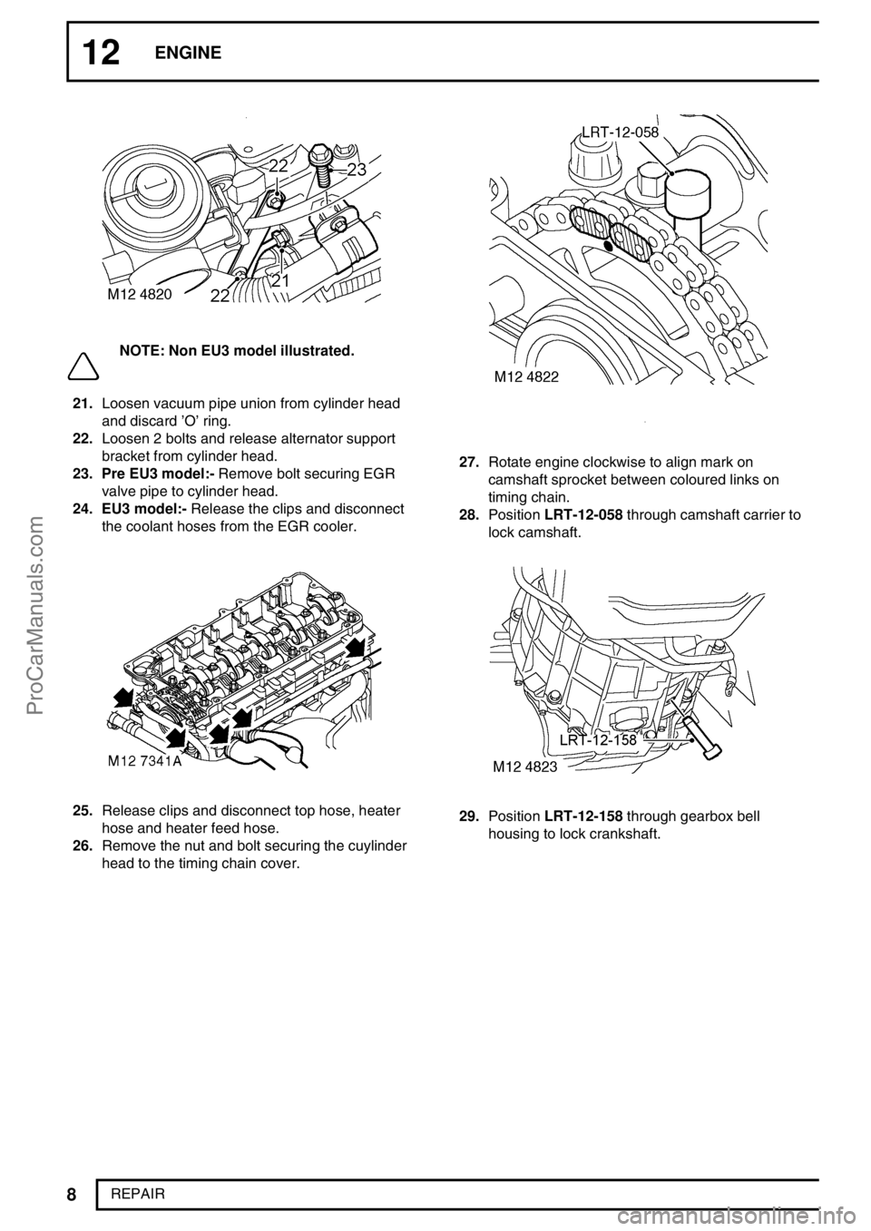
NOTE: Non EU3 model illustrated.
21.Loosen vacuum pipe union from cylinder head
and discard’O’ring.
22.Loosen 2 bolts and release alternator support
bracket from cylinder head.
23. Pre EU3 model:-Remove bolt securing EGR
valve pipe to cylinder head.
24. EU3 model:-Release the clips and disconnect
the coolant hoses from the EGR cooler.
25.Release clips and disconnect top hose, heater
hose and heater feed hose.
26.Remove the nut and bolt securing the cuylinder
head to the timing chain cover.
27.Rotate engine clockwise to align mark on
camshaft sprocket between coloured links on
timing chain.
28.PositionLRT-12-058through camshaft carrier to
lock camshaft.
29.PositionLRT-12-158through gearbox bell
housing to lock crankshaft.
ProCarManuals.com
Page 134 of 667
ENGINE
9
REPAIR
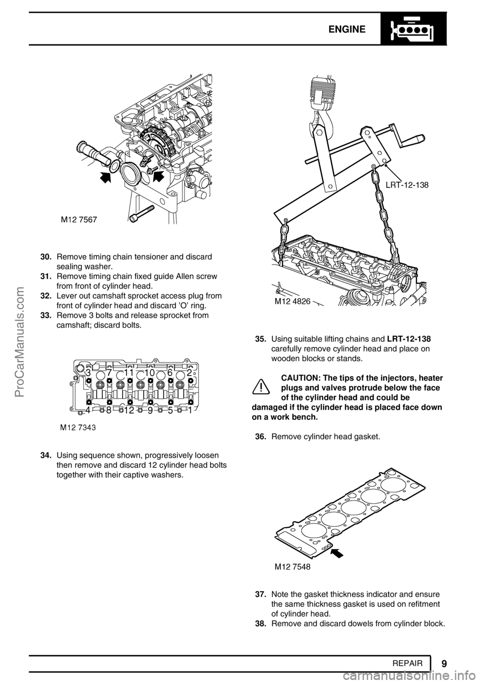
30.Remove timing chain tensioner and discard
sealing washer.
31.Remove timing chain fixed guide Allen screw
from front of cylinder head.
32.Lever out camshaft sprocket access plug from
front of cylinder head and discard’O’ring.
33.Remove 3 bolts and release sprocket from
camshaft; discard bolts.
34.Using sequence shown, progressively loosen
then remove and discard 12 cylinder head bolts
together with their captive washers.
35.Using suitable lifting chains andLRT-12-138
carefully remove cylinder head and place on
wooden blocks or stands.
CAUTION: The tips of the injectors, heater
plugs and valves protrude below the face
of the cylinder head and could be
damaged if the cylinder head is placed face down
on a work bench.
36.Remove cylinder head gasket.
37.Note the gasket thickness indicator and ensure
the same thickness gasket is used on refitment
of cylinder head.
38.Remove and discard dowels from cylinder block.
ProCarManuals.com