check engine LAND ROVER DISCOVERY 1999 User Guide
[x] Cancel search | Manufacturer: LAND ROVER, Model Year: 1999, Model line: DISCOVERY, Model: LAND ROVER DISCOVERY 1999Pages: 1529, PDF Size: 34.8 MB
Page 119 of 1529
CAPACITIES, FLUIDS, LUBRICANTS AND SEALANTS
09-2
Fluids
Anti-freeze
Use Havoline Extended Life Coolant (XLC), or any
ethylene glycol based anti-freeze (containing no
methanol) with only Organic Acid Technology (OAT)
corrosion inhibitors, to protect the cooling system
CAUTION: No other anti-freeze should be used
with Havoline Extended Life Coolant.
The cooling system should be drained, flushed and
refilled with the correct amount of anti-freeze solution
at the intervals given on the Service Maintenance
Check Sheet.
After filling with anti-freeze solution, attach a warning
label to a prominent position on the vehicle stating
the type of anti-freeze contained in the cooling
system to ensure that the correct type is used for
topping-up.
Brake/Clutch fluid
Use only DOT 4 brake fluid.
PAS fluid
Use Texaco cold climate power assisted steering
fluid PSF 14315.
ACE fluid
Where ambient temperature falls below -20° C (-4°
F), use only Texaco cold climate power assisted
steering fluid PSF 14315. Where ambient
temperature remains above -20° C (-4° F), use either
Texaco cold climate power assisted steering fluid ,
Dexron 11 or Dexron 111 non-synthetic fluid.
Air conditioning
Use only refrigerant R134a.
Refrigerant oil
Use only Nippon Denso ND-oil 8.
Refrigerant oil absorbs water and must not be stored
for long periods. Do not pour unused oil back into the
container.
NOTE: The total quantity of refrigerant oil in the
system is 180 ml.
CAUTION: Do not use any other type of
refrigerant oil.
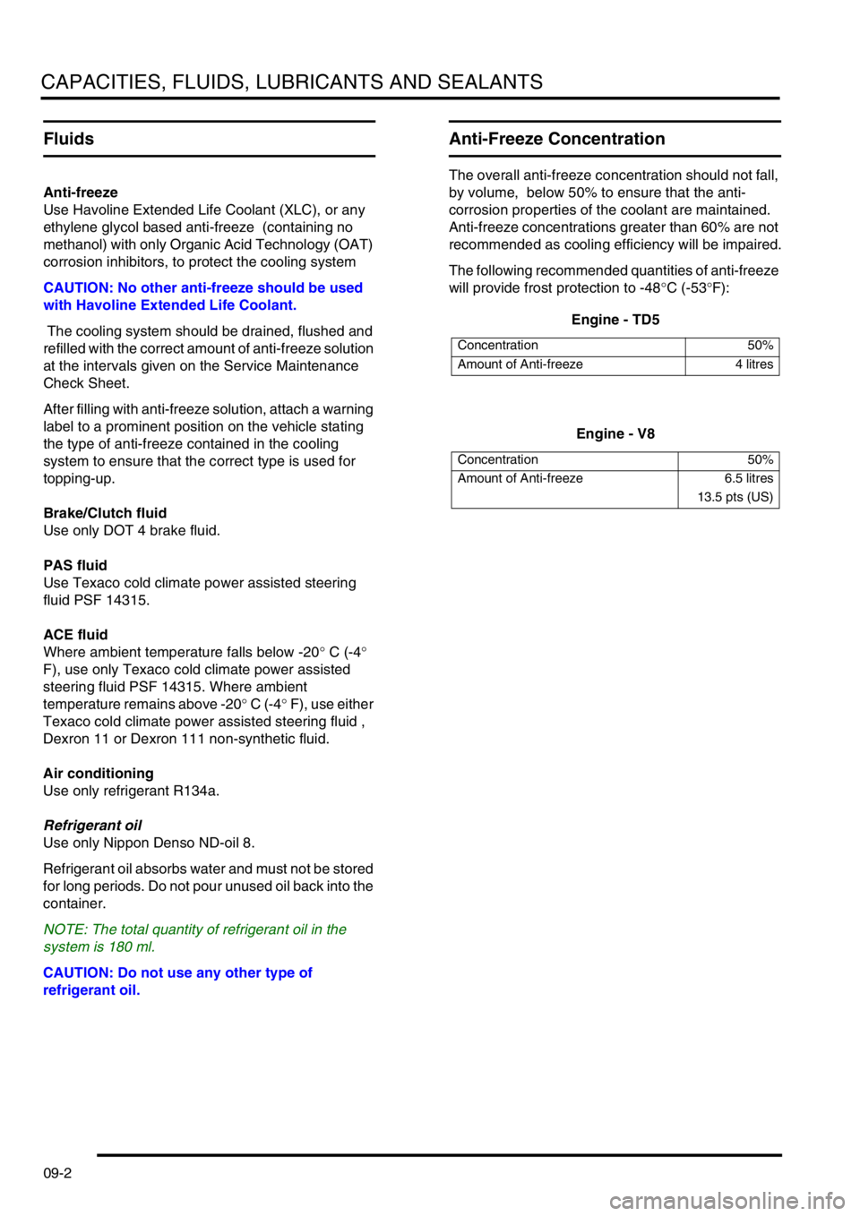
Anti-Freeze Concentration
The overall anti-freeze concentration should not fall,
by volume, below 50% to ensure that the anti-
corrosion properties of the coolant are maintained.
Anti-freeze concentrations greater than 60% are not
recommended as cooling efficiency will be impaired.
The following recommended quantities of anti-freeze
will provide frost protection to -48°C (-53°F):
Engine - TD5
Engine - V8
Concentration 50%
Amount of Anti-freeze 4 litres
Concentration 50%
Amount of Anti-freeze 6.5 litres
13.5 pts (US)
Page 132 of 1529
MAINTENANCE
PROCEDURES 10-9
Air suspension intake filter
Check
1.Check condition of filter and that filter is clean,
replace if necessary.
+ REAR SUSPENSION, REPAIRS,
Filter - intake - SLS.
Anti-freeze
Replace
1.Replace anti-freeze.
+ COOLING SYSTEM - Td5,
ADJUSTMENTS, Drain and refill.
+ COOLING SYSTEM - V8,
ADJUSTMENTS, Drain and refill.
Cooling system
Check
1.Check cooling, intercooler and heating systems
for leaks; hoses and oil pipes for security and
condition.
2.Check accessible hose clips for tightness.
3.Check coolant level, top-up if necessary.
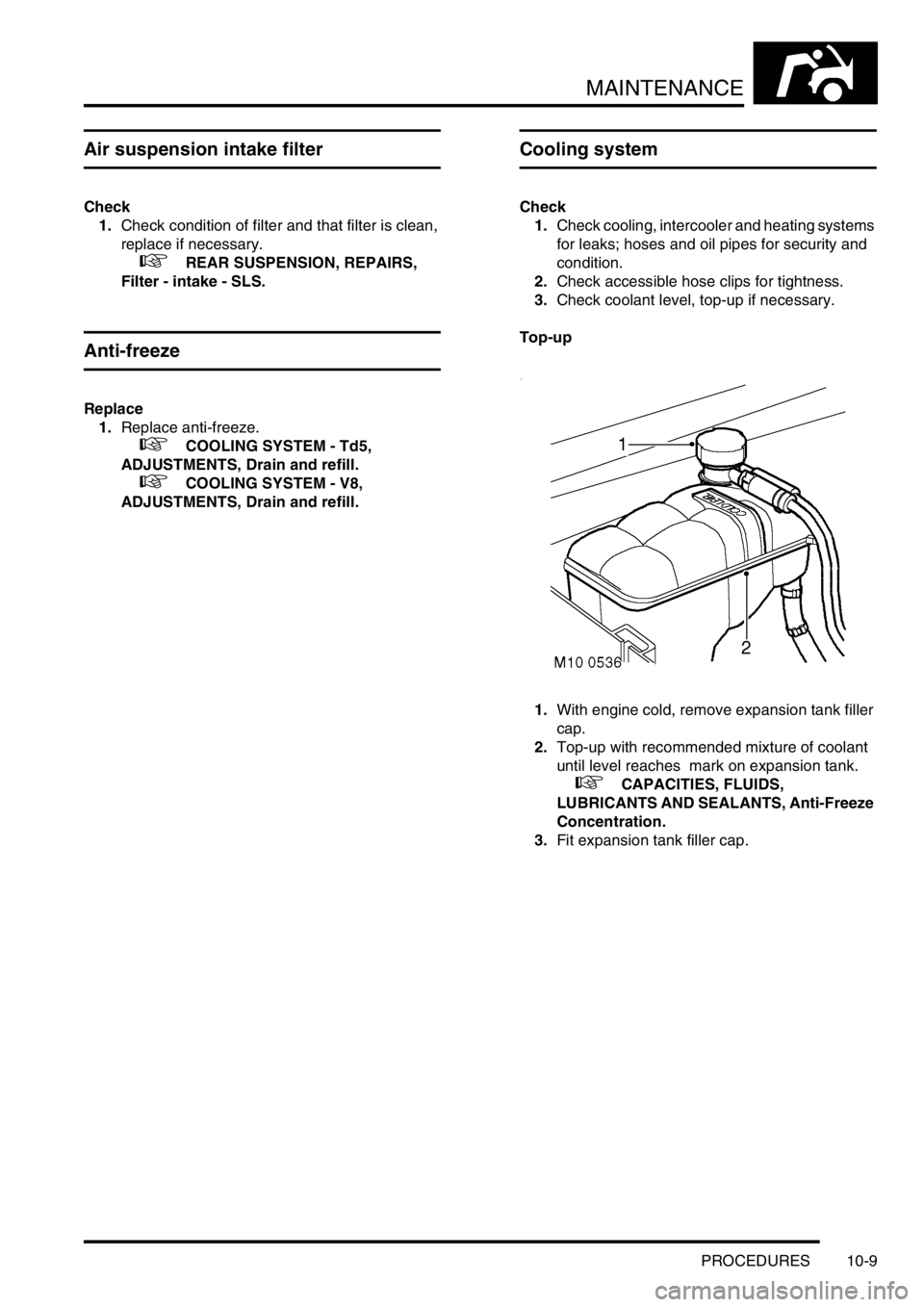
Top-up
1.With engine cold, remove expansion tank filler
cap.
2.Top-up with recommended mixture of coolant
until level reaches mark on expansion tank.
+ CAPACITIES, FLUIDS,
LUBRICANTS AND SEALANTS, Anti-Freeze
Concentration.
3.Fit expansion tank filler cap.
Page 134 of 1529
MAINTENANCE
PROCEDURES 10-11
Auxiliary drive belt
Check
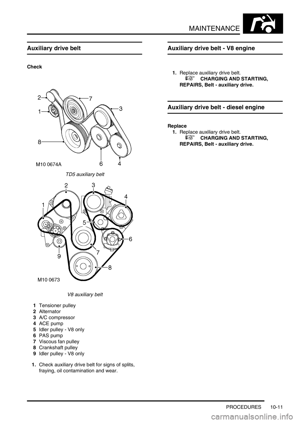
TD5 auxiliary belt
V8 auxiliary belt
1Tensioner pulley
2Alternator
3A/C compressor
4ACE pump
5Idler pulley - V8 only
6PAS pump
7Viscous fan pulley
8Crankshaft pulley
9Idler pulley - V8 only
1.Check auxiliary drive belt for signs of splits,
fraying, oil contamination and wear.
Auxiliary drive belt - V8 engine
1.Replace auxiliary drive belt.
+ CHARGING AND STARTING,
REPAIRS, Belt - auxiliary drive.
Auxiliary drive belt - diesel engine
Replace
1.Replace auxiliary drive belt.
+ CHARGING AND STARTING,
REPAIRS, Belt - auxiliary drive.
Page 139 of 1529
MAINTENANCE
10-16 PROCEDURES
Engine oil filter - diesel engine
Replace
1.Replace oil filter.
+ ENGINE - Td5, REPAIRS, Filter - oil.
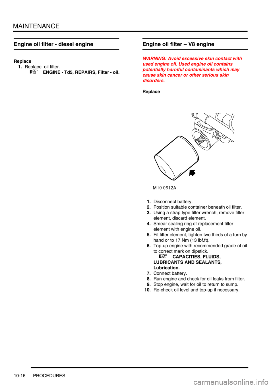
Engine oil filter – V8 engine
WARNING: Avoid excessive skin contact with
used engine oil. Used engine oil contains
potentially harmful contaminants which may
cause skin cancer or other serious skin
disorders.
Replace
1.Disconnect battery.
2.Position suitable container beneath oil filter.
3.Using a strap type filter wrench, remove filter
element, discard element.
4.Smear sealing ring of replacement filter
element with engine oil.
5.Fit filter element, tighten two thirds of a turn by
hand or to 17 Nm (13 lbf.ft).
6.Top-up engine with recommended grade of oil
to correct mark on dipstick.
+ CAPACITIES, FLUIDS,
LUBRICANTS AND SEALANTS,
Lubrication.
7.Connect battery.
8.Run engine and check for oil leaks from filter.
9.Stop engine, wait for oil to return to sump.
10.Re-check oil level and top-up if necessary.
Page 147 of 1529
MAINTENANCE
10-24 PROCEDURES
Brake hose, brake, fuel, ACE, clutch
pipes and unions/electrical harnesses
Check – General
1.Check brake servo hose for cracks, leaks and
chafing.
2.Check brake, clutch pipes and unions for
chafing, leaks and corrosion and that all pipes
and hoses are correctly routed and secure.
3.Check electrical harnesses for chafing and
damage.
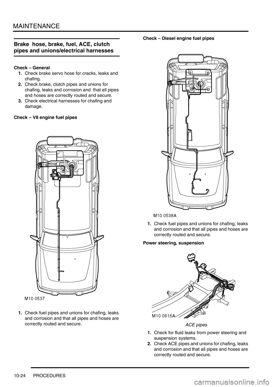
Check – V8 engine fuel pipes
1.Check fuel pipes and unions for chafing, leaks
and corrosion and that all pipes and hoses are
correctly routed and secure. Check – Diesel engine fuel pipes
1.Check fuel pipes and unions for chafing, leaks
and corrosion and that all pipes and hoses are
correctly routed and secure.
Power steering, suspension
ACE pipes
1.Check for fluid leaks from power steering and
suspension systems.
2.Check ACE pipes and unions for chafing, leaks
and corrosion and that all pipes and hoses are
correctly routed and secure.
Page 148 of 1529
MAINTENANCE
PROCEDURES 10-25
Engine, gearbox, transfer box and axles
Check
1.Check for oil leaks from engine, gearbox
(manual and automatic), transfer box and front
and rear axles; pay particular attention to areas
around oil seals.
Exhaust system
Check
1.Check for signs of exhaust system leaks,
damage and security.
Steering box and front suspension
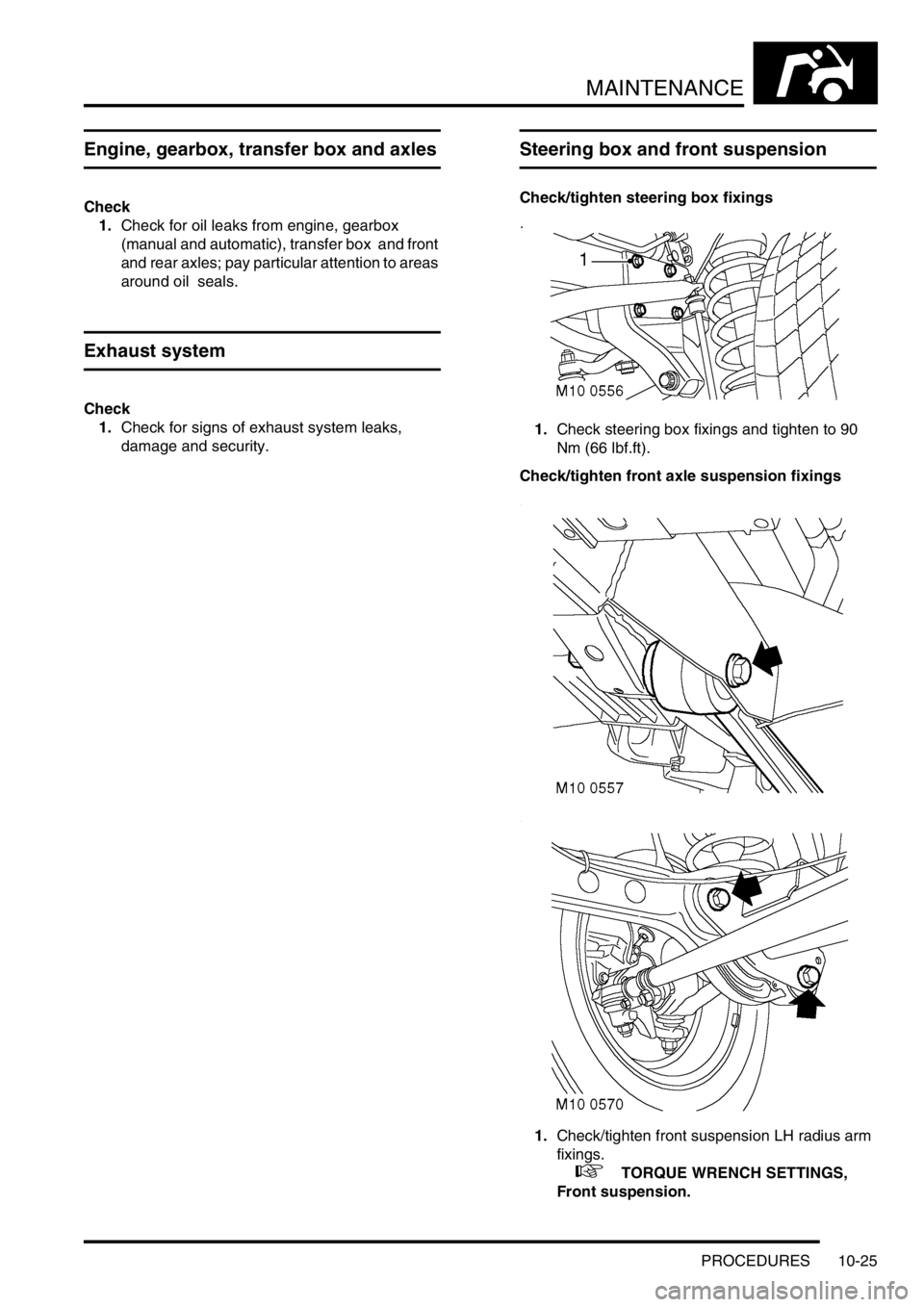
Check/tighten steering box fixings
1.Check steering box fixings and tighten to 90
Nm (66 lbf.ft).
Check/tighten front axle suspension fixings
1.Check/tighten front suspension LH radius arm
fixings.
+ TORQUE WRENCH SETTINGS,
Front suspension.
Page 153 of 1529
MAINTENANCE
10-30 PROCEDURES
Engine mountings - V8 engine
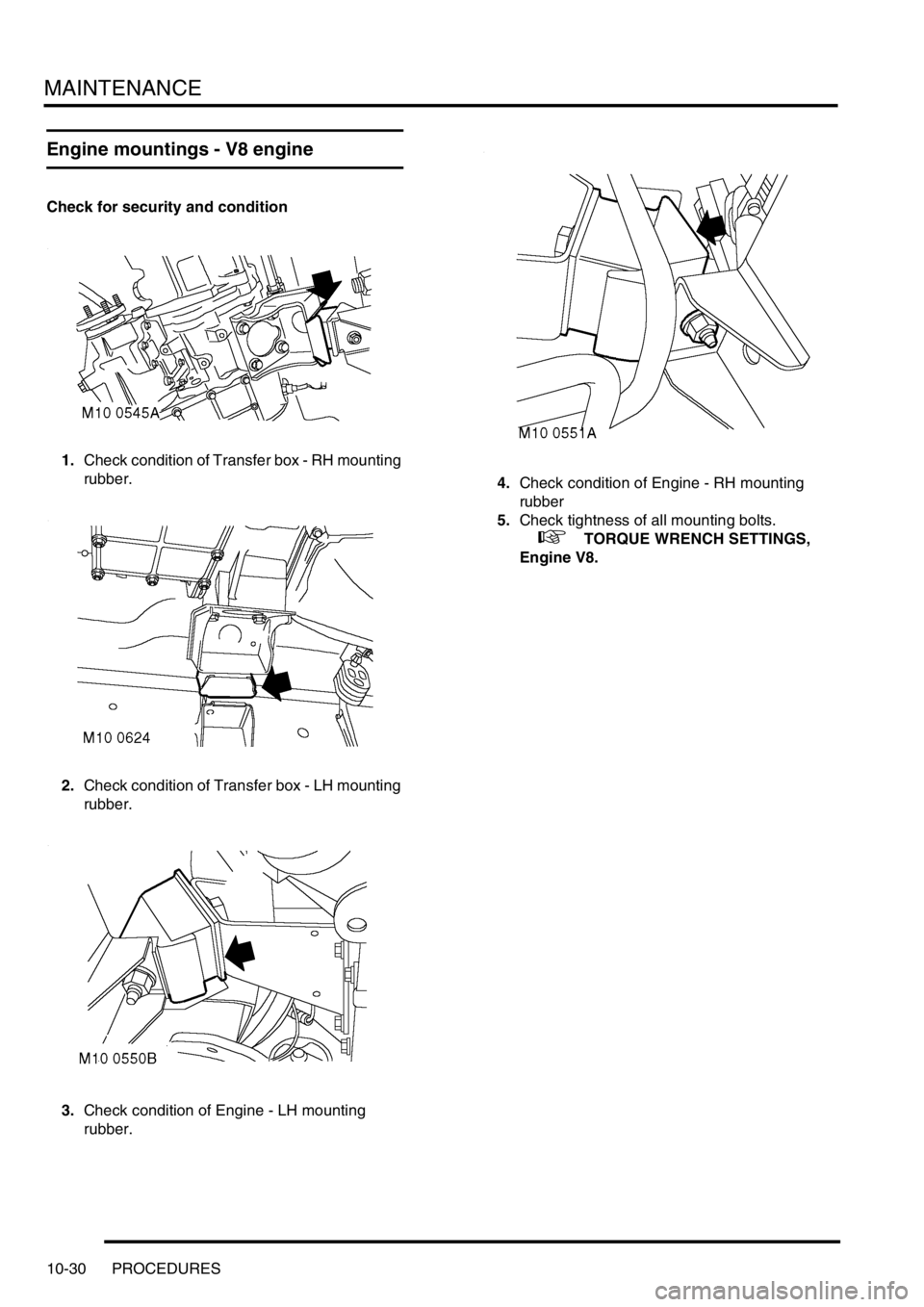
Check for security and condition
1.Check condition of Transfer box - RH mounting
rubber.
2.Check condition of Transfer box - LH mounting
rubber.
3.Check condition of Engine - LH mounting
rubber.4.Check condition of Engine - RH mounting
rubber
5.Check tightness of all mounting bolts.
+ TORQUE WRENCH SETTINGS,
Engine V8.
Page 154 of 1529
MAINTENANCE
PROCEDURES 10-31
Road/roller test
WARNING: Roller test must be restricted to 3
mph (5 km/h). If 2 wheel rolling road is to be used,
disconnect propeller shaft from the transfer box
output shaft driving the axle which is NOT on the
rolling road.
Testing
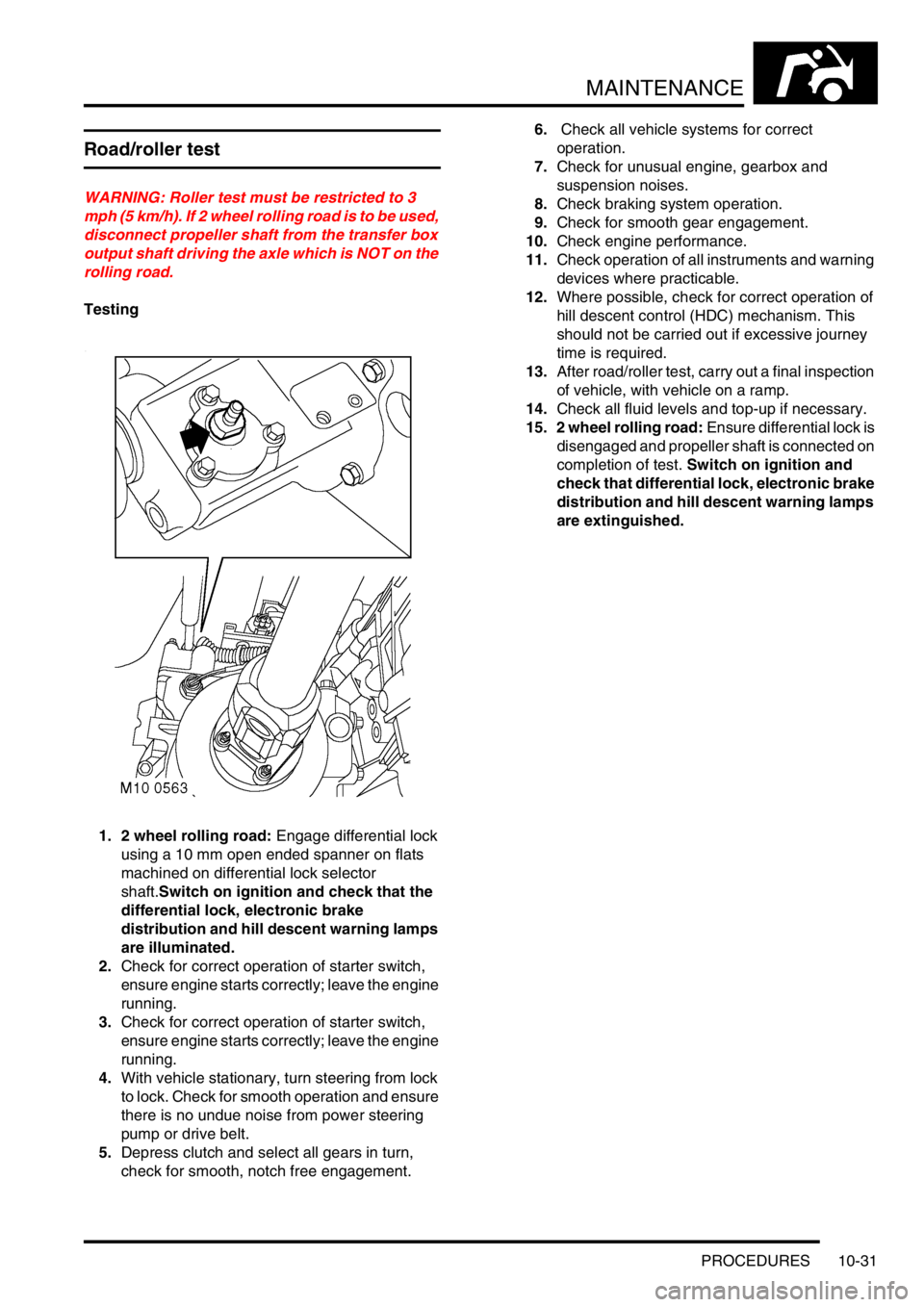
1. 2 wheel rolling road: Engage differential lock
using a 10 mm open ended spanner on flats
machined on differential lock selector
shaft.Switch on ignition and check that the
differential lock, electronic brake
distribution and hill descent warning lamps
are illuminated.
2.Check for correct operation of starter switch,
ensure engine starts correctly; leave the engine
running.
3.Check for correct operation of starter switch,
ensure engine starts correctly; leave the engine
running.
4.With vehicle stationary, turn steering from lock
to lock. Check for smooth operation and ensure
there is no undue noise from power steering
pump or drive belt.
5.Depress clutch and select all gears in turn,
check for smooth, notch free engagement.6. Check all vehicle systems for correct
operation.
7.Check for unusual engine, gearbox and
suspension noises.
8.Check braking system operation.
9.Check for smooth gear engagement.
10.Check engine performance.
11.Check operation of all instruments and warning
devices where practicable.
12.Where possible, check for correct operation of
hill descent control (HDC) mechanism. This
should not be carried out if excessive journey
time is required.
13.After road/roller test, carry out a final inspection
of vehicle, with vehicle on a ramp.
14.Check all fluid levels and top-up if necessary.
15. 2 wheel rolling road: Ensure differential lock is
disengaged and propeller shaft is connected on
completion of test. Switch on ignition and
check that differential lock, electronic brake
distribution and hill descent warning lamps
are extinguished.
Page 166 of 1529
ENGINE - V8
ADJUSTMENTS 12-2-11
ADJUST ME NTS
Engine oil pressure check
$% 12.90.09.01
Check
1.Remove oil pressure switch.
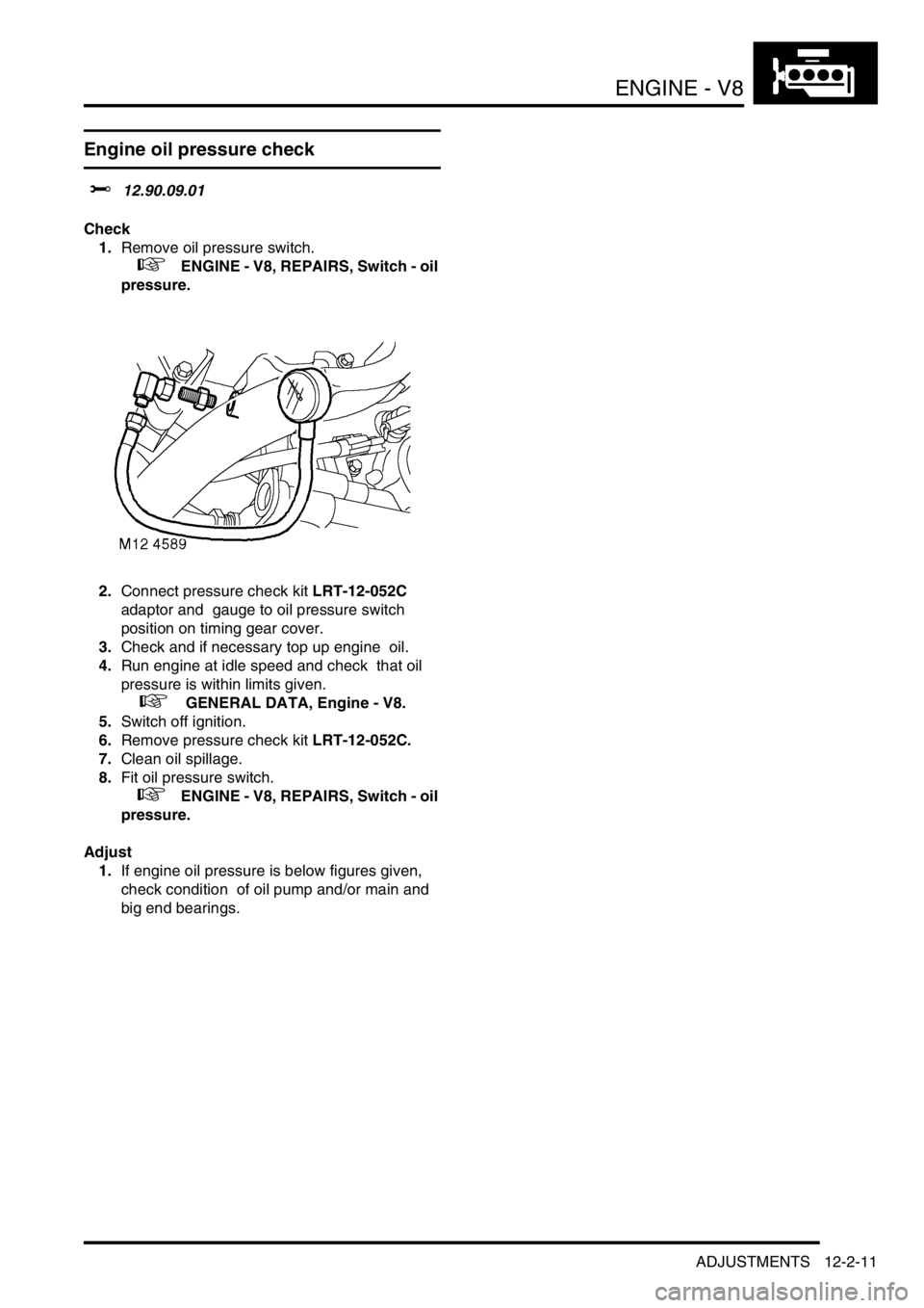
+ ENGINE - V8, REPAIRS, Switch - oil
pressure.
2.Connect pressure check kit LRT-12-052C
adaptor and gauge to oil pressure switch
position on timing gear cover.
3.Check and if necessary top up engine oil.
4.Run engine at idle speed and check that oil
pressure is within limits given.
+ GENERAL DATA, Engine - V8.
5.Switch off ignition.
6.Remove pressure check kit LRT-12-052C.
7.Clean oil spillage.
8.Fit oil pressure switch.
+ ENGINE - V8, REPAIRS, Switch - oil
pressure.
Adjust
1.If engine oil pressure is below figures given,
check condition of oil pump and/or main and
big end bearings.
Page 170 of 1529
ENGINE - V8
REPAIRS 12-2-15
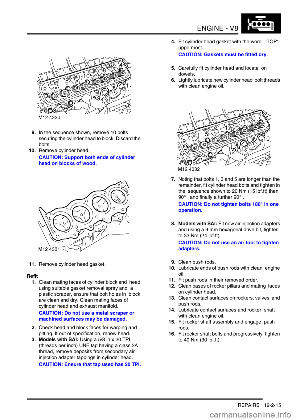
9.In the sequence shown, remove 10 bolts
securing the cylinder head to block. Discard the
bolts.
10.Remove cylinder head.
CAUTION: Support both ends of cylinder
head on blocks of wood.
11.Remove cylinder head gasket.
Refit
1.Clean mating faces of cylinder block and head
using suitable gasket removal spray and a
plastic scraper, ensure that bolt holes in block
are clean and dry. Clean mating faces of
cylinder head and exhaust manifold.
CAUTION: Do not use a metal scraper or
machined surfaces may be damaged.
2.Check head and block faces for warping and
pitting. If out of specification, renew head.
3. Models with SAI: Using a 5/8 in x 20 TPI
(threads per inch) UNF tap having a class 2A
thread, remove deposits from secondary air
injection adapter tappings in cylinder head.
CAUTION: Ensure that tap used has 20 TPI.4.Fit cylinder head gasket with the word 'TOP'
uppermost.
CAUTION: Gaskets must be fitted dry.
5.Carefully fit cylinder head and locate on
dowels.
6.Lightly lubricate new cylinder head bolt threads
with clean engine oil.
7.Noting that bolts 1, 3 and 5 are longer than the
remainder, fit cylinder head bolts and tighten in
the sequence shown to 20 Nm (15 lbf.ft) then
90° , and finally a further 90° .
CAUTION: Do not tighten bolts 180° in one
operation.
8. Models with SAI: Fit new air injection adapters
and using a 9 mm hexagonal drive bit, tighten
to 33 Nm (24 lbf.ft).
CAUTION: Do not use an air tool to tighten
adapters.
9.Clean push rods.
10.Lubricate ends of push rods with clean engine
oil.
11.Fit push rods in their removed order.
12.Clean bases of rocker pillars and mating faces
on cylinder head.
13.Clean contact surfaces on rockers, valves and
push rods.
14.Lubricate contact surfaces and rocker shaft
with clean engine oil.
15.Fit rocker shaft assembly and engage push
rods.
16.Fit rocker shaft bolts and progressively tighten
to 40 Nm (30 lbf.ft).