drain bolt LAND ROVER DISCOVERY 1999 User Guide
[x] Cancel search | Manufacturer: LAND ROVER, Model Year: 1999, Model line: DISCOVERY, Model: LAND ROVER DISCOVERY 1999Pages: 1529, PDF Size: 34.8 MB
Page 412 of 1529

FUEL DELIVERY SYSTEM - V8
REPAIRS 19-2-15
Tank - fuel
$% 19.55.01
Remove
1.Drain fuel tank.
+ FUEL DELIVERY SYSTEM - V8,
ADJUSTMENTS, Fuel tank - drain.
2.Raise rear of vehicle.
WARNING: Do not work on or under a
vehicle supported only by a jack. Always
support the vehicle on safety stands.
3. All except NAS models:Release clips
securing filler and breather hoses. Release
hoses from filler tube.
4. NAS models: Loosen securing clip and
release filler tube from fuel tank.
5.Disconnect fuel tank vent pipe from filler tube.
6.Support weight of fuel tank underneath cradle. 7.Remove 2 nuts and 2 bolts securing cradle to
chassis.
8.With assistance, lower LH side of fuel tank then
remove fuel tank from chassis.
9.Remove cradle from fuel tank.
Non NAS fuel tank
10.Remove 2 scrivets securing heat shield and
remove heat shield.
11. All except NAS models: Release securing clip
and remove breather hose from fuel tank.
Refit
1.Fit breather hose to fuel tank and secure with
clip.
2.Position heat shield and secure with scrivets.
3.With assistance, position fuel tank and cradle.
4.Fit nuts and bolts securing cradle to chassis.
Tighten bolts to 45 Nm (33 lbf.ft) and nuts to 26
Nm (19 lbf.ft).
5.Connect vent hose.
6.Connect breather and filler hoses and secure
with clips.
Page 432 of 1529

COOLING SYSTEM - V8
REPAIRS 26-2-17
16.Remove radiator assembly.
17.Release clip and remove bottom hose from
radiator.
18.Remove 2 bolts and remove extension
brackets from radiator.
19.Remove 2 captive nuts from radiator.
20.Remove 2 screws and remove gearbox oil
cooler from radiator.
21. If fitted: Remove 2 screws and remove engine
oil cooler from radiator.
22.Remove 2 rubber mountings from radiator.
23.Remove sealing strip from bottom of radiator.
24.Remove 2 cowl retaining clips from radiator. Refit
1.Fit cowl retaining clips to radiator.
2.Fit sealing strip to radiator.
3.Fit rubber mountings to radiator.
4.Fit gearbox oil cooler to radiator and secure
with screws.
5. If fitted: Fit engine oil cooler to radiator and
secure with screws.
6.Fit captive nuts to radiator.
7.Fit extension brackets to radiator and secure
with bolts.
8.Fit bottom hose to radiator and secure with clip.
9.Fit radiator and engage lower mountings in
chassis.
10.Ensure connections are clean, then secure
hoses to oil coolers.
11.Fit air conditioning condenser brackets and
secure with screws.
12.Fit radiator upper mounting brackets and
secure with bolts.
13.Fit LH horn and secure with nut.
14.Fit air deflectors and secure with scrivets.
15.Connect multiplug of gearbox oil temperature
sensor.
16.Fit front grille.
+ EXTERIOR FITTINGS, REPAIRS,
Grille - front - up to 03MY.
17.Connect bottom hose to thermostat housing
and secure with clip.
18.Connect top hose to radiator and secure with
clip.
19.Connect bleed hose to radiator and fit clip.
20.Fit lower fan cowl and secure with screws.
21.Fit viscous fan.
+ COOLING SYSTEM - V8, REPAIRS,
Fan - viscous.
22.Top up gearbox oil.
23.Top up engine oil.
24.Refill cooling system.
+ COOLING SYSTEM - V8,
ADJUSTMENTS, Drain and refill.
Page 434 of 1529

COOLING SYSTEM - V8
REPAIRS 26-2-19
Gasket - coolant pump
$% 26.50.02
Remove
1.Remove auxiliary drive belt.
+ CHARGING AND STARTING,
REPAIRS, Belt - auxiliary drive.
2.Drain cooling system.
+ COOLING SYSTEM - V8,
ADJUSTMENTS, Drain and refill.
3.Remove 3 bolts securing pulley to coolant
pump and remove pulley.
4.Release clip and disconnect feed hose from
coolant pump. 5.Remove 9 bolts securing coolant pump,
remove pump and discard gasket.
Refit
1.Clean coolant pump and mating face.
2.Fit new gasket and coolant pump to cylinder
block. Fit bolts and tighten to 24 Nm (18 lbf.ft).
3.Connect feed hose to coolant pump and secure
with clip.
4.Ensure mating faces of coolant pump pulley
and flange are clean. Fit pulley and tighten
bolts to 22 Nm (16 lbf.ft).
5.Fit auxiliary drive belt.
+ CHARGING AND STARTING,
REPAIRS, Belt - auxiliary drive.
6.Refill cooling system.
+ COOLING SYSTEM - V8,
ADJUSTMENTS, Drain and refill.
Page 474 of 1529

MANUAL GEARBOX - R380
DESCRIPTION AND OPERATION 37-3
1Front cover
2Input shaft oil seal
3Oil filler/level plug
4Sealing washer
5Oil drain plug
6Gear case
7Interlock spool retainer, bolt and 'O' ring
8Centre plate
9Locating dowels
10Selector plug, detent balls and spring
11Splash shield and retaining bolt
12Extension housing
13Gate plate and retaining bolt
14Interlock spool retainer, retaining bolt and 'O'
ring – if fitted – extension housing
15Inhibitor cam spring
16Inhibitor cam
17Reverse inhibitor shaft
18Output shaft oil seal
19Oil seal collar
20Oil pump and retaining bolt
21'O' ring
22Reverse lamp switch23Oil by-pass block - UK and European models
24Bolt - oil by-pass block
25'O' ring - oil by-pass block
26Thermostat and housing - non UK and non
European models
27'O' ring - thermostat housing
28Bolt - thermostat housing
29Oil pick-up pipe
30Oil filter
31Oil pick-up ring
32Rubber gaiter
33Cable tie
34Upper gear lever
35Clamp bolt
36Bias springs
37Bolts and washers - bias adjusting plate and
housing
38Bias adjusting plate
39Lower gear lever and ball
40Railko bush
41Oil seal
42Gear change housing
Page 478 of 1529

MANUAL GEARBOX - R380
DESCRIPTION AND OPERATION 37-7
Description
General
The R380 all synchromesh gearbox has five forward speeds and reverse and is mounted in line with the engine. The
clutch bell housing is bolted to the front of the gearbox and the transfer box is mounted at the rear.
Gearbox casings
Gearbox casings consist of a front cover, gearcase, centre plate and extension housing. All casings with the exception
of the front cover are located to each other by dowels and sealed. Gearbox filler/level and drain plugs are located in
the gearcase.
Reverse lamp switch
A reverse lamp switch is inserted into the extension housing. Selection of reverse gear will close the switch allowing
current from fuse 25 to flow through the switch to illuminate the reverse lamps. The switch also provides a feed to the
BCU and the electrochromic automatic interior mirror - if fitted; the mirror moving from the dimmed position if
applicable.
Gearchange assembly
The gearchange assembly is bolted to the top of the gearcase, the upper gear lever being attached to the lower gear
lever by means of a clamp bolt. The lower gear lever ball is housed in a Railko bush inserted in the gear change
housing, the end of the lever locating in the selector yoke which is attached to the end of the selector shaft. Bias
springs provide a positive return of the gear lever to the neutral position with selection of 1st/2nd and 5th/reverse gears
being against bias spring pressure. Spring loaded detent balls fitted in the centre plate locate in grooves in the selector
shaft to provide positive gear and neutral selection.
Lubrication
Lubrication is by an oil pump located in the extension housing and driven by the layshaft with additional lubrication
being provided by splash. The pump directs oil via a filter and internal drillings in the output shaft to lubricate the
components. On non UK and non European models, provision for oil cooling is by means of a thermostat housed in
a cover bolted to the side of the extension housing. The cover incorporates tappings for connections to an oil cooler.
On UK and European models, the thermostat and cover are replaced by an oil by-pass block.
Internal pressures produced within the gearbox are vented to atmosphere via a plastic breather pipe. The pipe is
attached to the extension housing and is routed across the top of the gearcase and secured at the open end by a clip
attached to the engine cylinder block.
Selector shaft and forks
Selector forks for 1st/2nd, 3rd/4th and 5th/reverse gears are located on a single selector shaft; the 1st/2nd and 3rd/
4th selector forks are inside the main gearcase whilst the 5th/reverse selector fork is inside the extension housing.
Each of the selector forks locates inside its corresponding synchromesh hub.
Synchromesh assemblies
Each synchromesh assembly is located on the output shaft adjacent to its corresponding gears and comprises a
synchromesh ring, hub, slippers and sleeve. The hubs and slippers are retained in the sleeves by means of spring
clips. 1st/2nd and 3rd synchromesh assemblies are fitted with double synchromesh rings whilst 4th, 5th and reverse
assemblies are fitted with single rings.
The gear train
The gear train comprises an input shaft, output shaft, layshaft and reverse idler shaft together with their appropriate
gears and synchromesh assemblies.
The gear train input shaft, output shaft and layshaft are supported by taper roller bearings with all gears on the input
and output shafts running on caged needle roller bearings. Layshaft gears are integral with the shaft with the
exception of reverse/5th gears which are splined to the shaft and retained with a nut. 1st, 2nd, 3rd and 4th gears are
shot peened to improve durability. The reverse idler shaft and gear are supported in the centre plate by a caged
needle roller bearing. End-float of the output shaft and layshaft is controlled by selective shims located in the centre
plate whilst reverse idler shaft end-float is controlled by a selective shim located behind reverse gear.
Page 483 of 1529

MANUAL GEARBOX - R380
37-12 REPAIRS
Gearbox - V8
$% 37.20.02.99
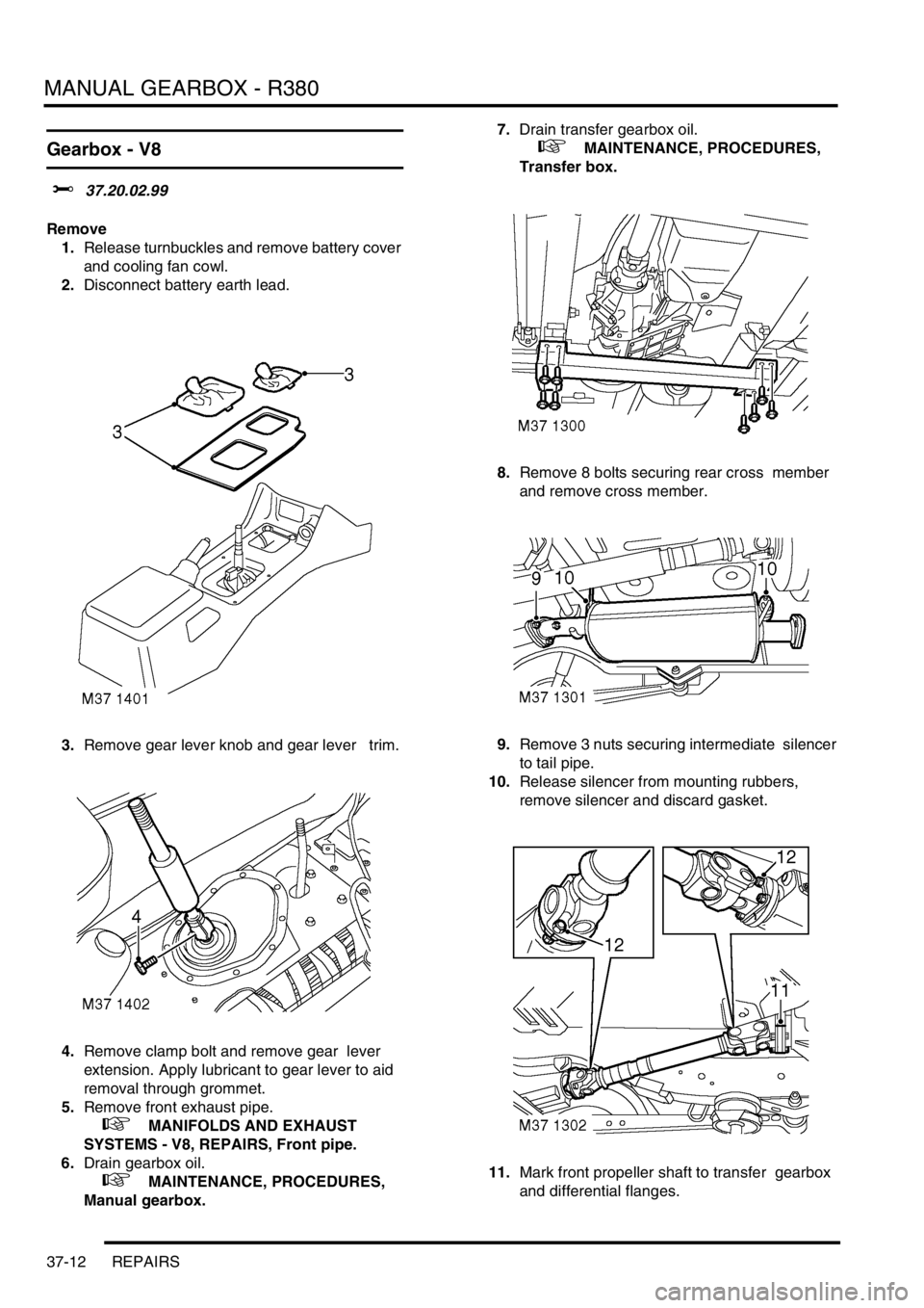
Remove
1.Release turnbuckles and remove battery cover
and cooling fan cowl.
2.Disconnect battery earth lead.
3.Remove gear lever knob and gear lever trim.
4.Remove clamp bolt and remove gear lever
extension. Apply lubricant to gear lever to aid
removal through grommet.
5.Remove front exhaust pipe.
+ MANIFOLDS AND EXHAUST
SYSTEMS - V8, REPAIRS, Front pipe.
6.Drain gearbox oil.
+ MAINTENANCE, PROCEDURES,
Manual gearbox.7.Drain transfer gearbox oil.
+ MAINTENANCE, PROCEDURES,
Transfer box.
8.Remove 8 bolts securing rear cross member
and remove cross member.
9.Remove 3 nuts securing intermediate silencer
to tail pipe.
10.Release silencer from mounting rubbers,
remove silencer and discard gasket.
11.Mark front propeller shaft to transfer gearbox
and differential flanges.
Page 487 of 1529

MANUAL GEARBOX - R380
37-16 REPAIRS
Gearbox - Diesel
$% 37.20.02.99
Remove
1.Release turn buckles and remove battery cover
and cooling fan cowl.
2.Disconnect battery earth lead.
3.Remove gear lever knob and gear lever trim.
4.Remove clamp bolt and remove gear lever
extension.
5.Apply a little lubricant to gear lever to aid
removal through grommet.
6.Remove exhaust front pipe.
+ MANIFOLDS AND EXHAUST
SYSTEMS - Td5, REPAIRS, Pipe - front.7.Remove starter motor.
+ CHARGING AND STARTING,
REPAIRS, Starter motor - diesel.
8.Drain gearbox oil.
+ MAINTENANCE, PROCEDURES,
Manual gearbox.
9.Drain transfer gearbox oil.
+ MAINTENANCE, PROCEDURES,
Transfer box.
10.Remove 3 nuts securing intermediate silencer
to tail pipe.
11.Release silencer from mounting rubbers,
remove silencer and discard gasket.
12.Remove front propeller shaft.
+ PROPELLER SHAFTS, REPAIRS,
Propeller shaft - front.
13.Remove rear propeller shaft.
+ PROPELLER SHAFTS, REPAIRS,
Propeller shaft - rear.
Page 510 of 1529

MANUAL GEARBOX - R380
OVERHAUL 37-39
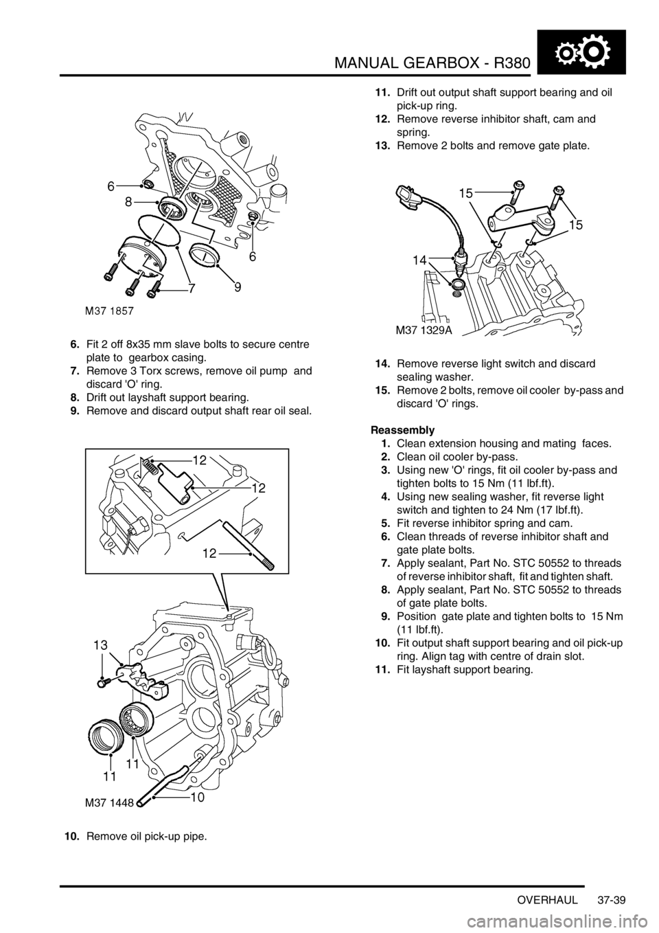
6.Fit 2 off 8x35 mm slave bolts to secure centre
plate to gearbox casing.
7.Remove 3 Torx screws, remove oil pump and
discard 'O' ring.
8.Drift out layshaft support bearing.
9.Remove and discard output shaft rear oil seal.
10.Remove oil pick-up pipe. 11.Drift out output shaft support bearing and oil
pick-up ring.
12.Remove reverse inhibitor shaft, cam and
spring.
13.Remove 2 bolts and remove gate plate.
14.Remove reverse light switch and discard
sealing washer.
15.Remove 2 bolts, remove oil cooler by-pass and
discard 'O' rings.
Reassembly
1.Clean extension housing and mating faces.
2.Clean oil cooler by-pass.
3.Using new 'O' rings, fit oil cooler by-pass and
tighten bolts to 15 Nm (11 lbf.ft).
4.Using new sealing washer, fit reverse light
switch and tighten to 24 Nm (17 lbf.ft).
5.Fit reverse inhibitor spring and cam.
6.Clean threads of reverse inhibitor shaft and
gate plate bolts.
7.Apply sealant, Part No. STC 50552 to threads
of reverse inhibitor shaft, fit and tighten shaft.
8.Apply sealant, Part No. STC 50552 to threads
of gate plate bolts.
9.Position gate plate and tighten bolts to 15 Nm
(11 lbf.ft).
10.Fit output shaft support bearing and oil pick-up
ring. Align tag with centre of drain slot.
11.Fit layshaft support bearing.
Page 529 of 1529

TRANSFER BOX - LT230SE
41-4 DESCRIPTION AND OPERATION
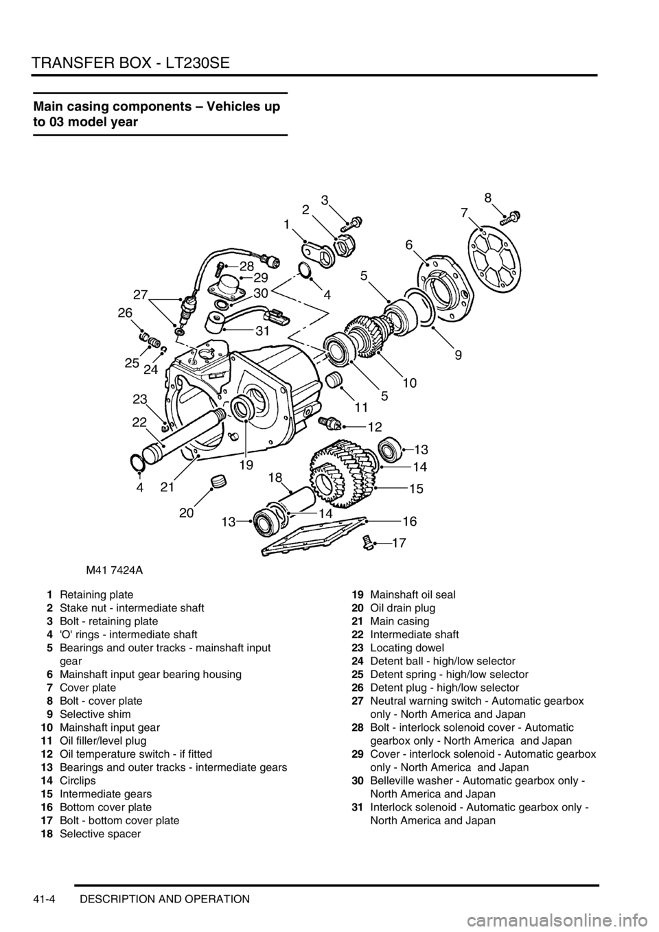
Main casing components – Vehicles up
to 03 model year
1Retaining plate
2Stake nut - intermediate shaft
3Bolt - retaining plate
4'O' rings - intermediate shaft
5Bearings and outer tracks - mainshaft input
gear
6Mainshaft input gear bearing housing
7Cover plate
8Bolt - cover plate
9Selective shim
10Mainshaft input gear
11Oil filler/level plug
12Oil temperature switch - if fitted
13Bearings and outer tracks - intermediate gears
14Circlips
15Intermediate gears
16Bottom cover plate
17Bolt - bottom cover plate
18Selective spacer19Mainshaft oil seal
20Oil drain plug
21Main casing
22Intermediate shaft
23Locating dowel
24Detent ball - high/low selector
25Detent spring - high/low selector
26Detent plug - high/low selector
27Neutral warning switch - Automatic gearbox
only - North America and Japan
28Bolt - interlock solenoid cover - Automatic
gearbox only - North America and Japan
29Cover - interlock solenoid - Automatic gearbox
only - North America and Japan
30Belleville washer - Automatic gearbox only -
North America and Japan
31Interlock solenoid - Automatic gearbox only -
North America and Japan
Page 530 of 1529

TRANSFER BOX - LT230SE
DESCRIPTION AND OPERATION 41-5
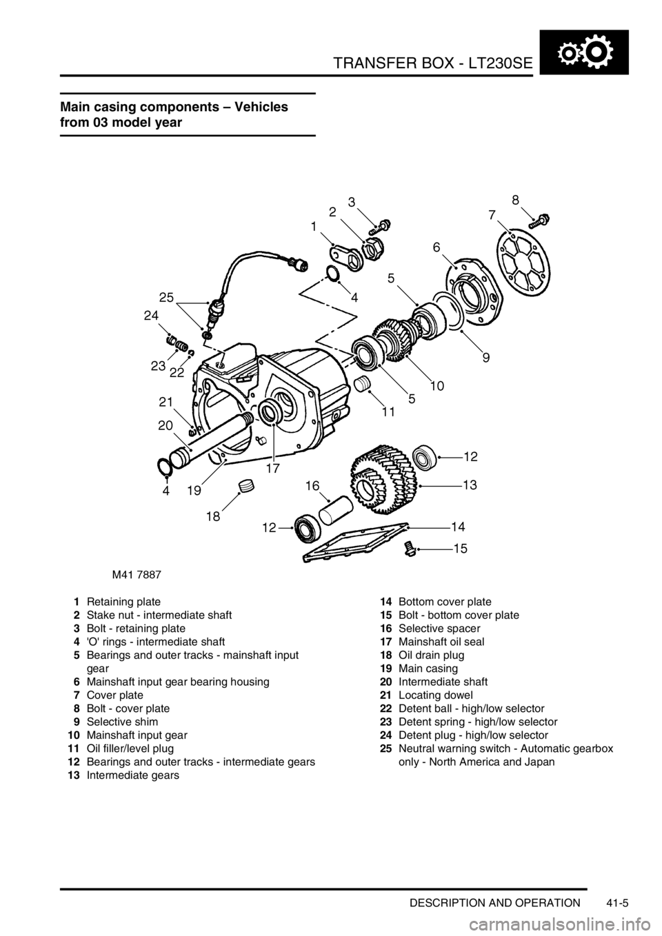
Main casing components – Vehicles
from 03 model year
1Retaining plate
2Stake nut - intermediate shaft
3Bolt - retaining plate
4'O' rings - intermediate shaft
5Bearings and outer tracks - mainshaft input
gear
6Mainshaft input gear bearing housing
7Cover plate
8Bolt - cover plate
9Selective shim
10Mainshaft input gear
11Oil filler/level plug
12Bearings and outer tracks - intermediate gears
13Intermediate gears14Bottom cover plate
15Bolt - bottom cover plate
16Selective spacer
17Mainshaft oil seal
18Oil drain plug
19Main casing
20Intermediate shaft
21Locating dowel
22Detent ball - high/low selector
23Detent spring - high/low selector
24Detent plug - high/low selector
25Neutral warning switch - Automatic gearbox
only - North America and Japan