headlamp LAND ROVER DISCOVERY 1999 Service Manual
[x] Cancel search | Manufacturer: LAND ROVER, Model Year: 1999, Model line: DISCOVERY, Model: LAND ROVER DISCOVERY 1999Pages: 1529, PDF Size: 34.8 MB
Page 1259 of 1529
WIPERS AND WASHERS
84-24 REPAIRS
Pump - washer - screen and headlamp
$% 84.10.21
The following procedure also covers removal of the
rear screen washer pump and the headlamp washer
pump.
Remove
1. Headlamp washer pump: Remove front
bumper.
+ EXTERIOR FITTINGS, REPAIRS,
Bumper assembly - front.
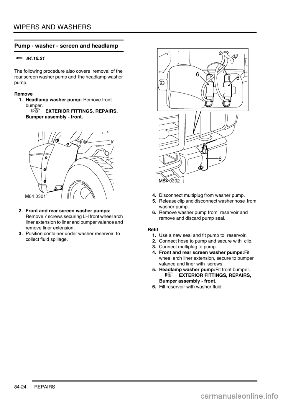
2. Front and rear screen washer pumps:
Remove 7 screws securing LH front wheel arch
liner extension to liner and bumper valance and
remove liner extension.
3.Position container under washer reservoir to
collect fluid spillage. 4.Disconnect multiplug from washer pump.
5.Release clip and disconnect washer hose from
washer pump.
6.Remove washer pump from reservoir and
remove and discard pump seal.
Refit
1.Use a new seal and fit pump to reservoir.
2.Connect hose to pump and secure with clip.
3.Connect multiplug to pump.
4. Front and rear screen washer pumps:Fit
wheel arch liner extension, secure to bumper
valance and liner with screws.
5. Headlamp washer pump:Fit front bumper.
+ EXTERIOR FITTINGS, REPAIRS,
Bumper assembly - front.
6.Fill reservoir with washer fluid.
Page 1262 of 1529
WIPERS AND WASHERS
REPAIRS 84-27
Jet - washer - headlamp
$% 84.20.08
The procedure to remove the headlamp washer jet
on 03MY vehicles is detailed in the front bumper
finisher job.
+ EXTERIOR FITTINGS, REPAIRS, Trim
finisher - bumper - front - from 03MY.
Remove
1.Remove retaining screw cover from jet
housing.
2.Remove screw securing jet to bumper.
3.Release jet and withdraw sufficiently to gain
access to washer tube. Disconnect tube from
jet and remove jet.
Refit
1.Connect jet to washer tube, ensuring it is
pushed fully home.
2.Locate jet in bumper, retain with screw and fit
screw cover.
Jet - washer - rear screen
$% 84.30.09
Remove
1.Remove spare wheel.
2.Remove rear screen wiper blade.
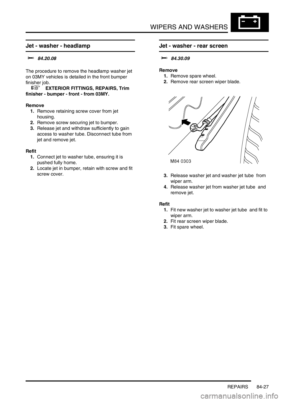
3.Release washer jet and washer jet tube from
wiper arm.
4.Release washer jet from washer jet tube and
remove jet.
Refit
1.Fit new washer jet to washer jet tube and fit to
wiper arm.
2.Fit rear screen wiper blade.
3.Fit spare wheel.
Page 1274 of 1529
LIGHTING
ADJUSTMENTS 86-2-1
LIGHTING ADJUST ME NTS
Headlamps beam alignment - up to 03MY
$% 86.40.17
Check
1.Ensure vehicle is unladen and tyres are at
correct pressures.
2. Models with SLS: Ensure vehicle is at
standard ride height.
3. Models with headlamp levelling: Ensure
headlamp levelling switch is set to '0'.
4.Align suitable beam setting equipment to
headlamp.
5.Switch headlamps on and measure main beam
settings. Beam must be 1.4% below the
horizontal and parallel to the vehicle centre line.
If necessary, adjust headlamp to get correct
beam settings.
6.Align beam setting equipment to 2nd headlamp
and repeat check.
7.Switch off headlamps and remove beam setting
equipment.Adjust
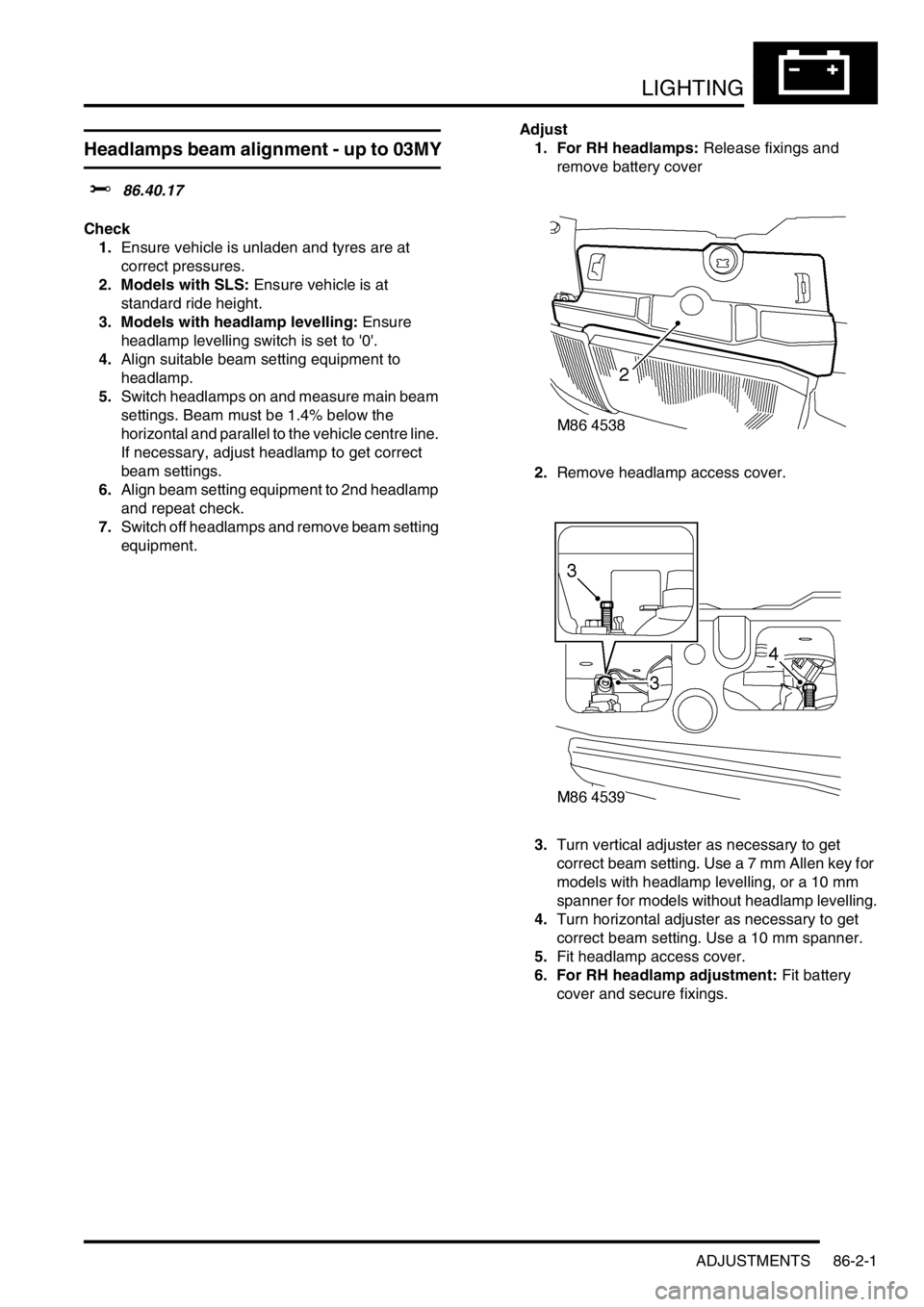
1. For RH headlamps: Release fixings and
remove battery cover
2.Remove headlamp access cover.
3.Turn vertical adjuster as necessary to get
correct beam setting. Use a 7 mm Allen key for
models with headlamp levelling, or a 10 mm
spanner for models without headlamp levelling.
4.Turn horizontal adjuster as necessary to get
correct beam setting. Use a 10 mm spanner.
5.Fit headlamp access cover.
6. For RH headlamp adjustment: Fit battery
cover and secure fixings.
Page 1275 of 1529
LIGHTING
86-2-2 ADJUSTMENTS
Headlamps beam alignment - from 03MY
$% 86.40.17
Check
1.Ensure vehicle is unladen and tyres are set at
the correct pressures.
2. Models with SLS: Ensure vehicle is at the
standard ride height.
3. Models without SLS: Set headlamp leveling
switch to zero.
4.Align beam setting equipment to headlamp.
5.Switch on headlamps. Headlamp setting 1.2%
below horizontal and parallel.
6.Align beam setting equipment to second
headlamp and repeat the check.
Adjust
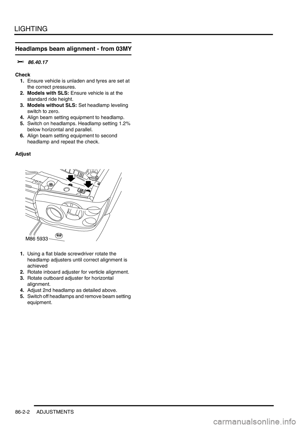
1.Using a flat blade screwdriver rotate the
headlamp adjusters until correct alignment is
achieved
2.Rotate inboard adjuster for verticle alignment.
3.Rotate outboard adjuster for horizontal
alignment.
4.Adjust 2nd headlamp as detailed above.
5.Switch off headlamps and remove beam setting
equipment.
Page 1276 of 1529
LIGHTING
REPAIRS 86-2-3
REPAIRS
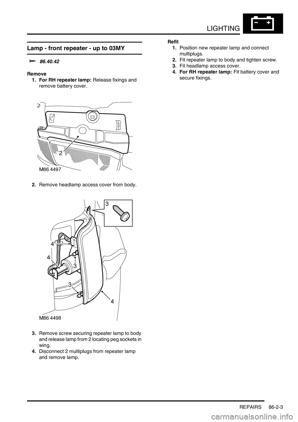
Lamp - front repeater - up to 03MY
$% 86.40.42
Remove
1. For RH repeater lamp: Release fixings and
remove battery cover.
2.Remove headlamp access cover from body.
3.Remove screw securing repeater lamp to body
and release lamp from 2 locating peg sockets in
wing.
4.Disconnect 2 multiplugs from repeater lamp
and remove lamp. Refit
1.Position new repeater lamp and connect
multiplugs.
2.Fit repeater lamp to body and tighten screw.
3.Fit headlamp access cover.
4. For RH repeater lamp: Fit battery cover and
secure fixings.
Page 1277 of 1529
LIGHTING
86-2-4 REPAIRS
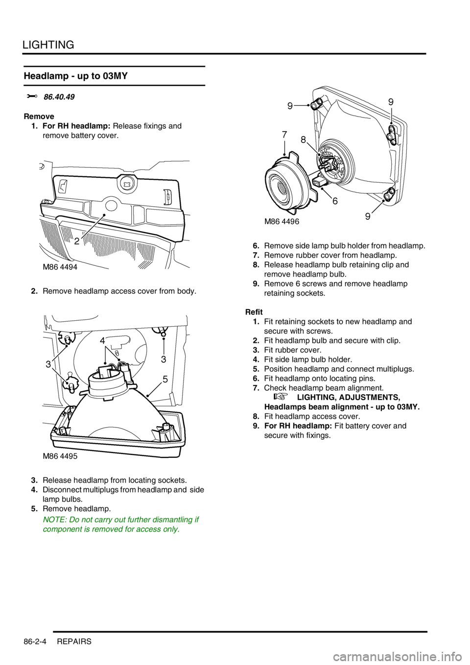
Headlamp - up to 03MY
$% 86.40.49
Remove
1. For RH headlamp: Release fixings and
remove battery cover.
2.Remove headlamp access cover from body.
3.Release headlamp from locating sockets.
4.Disconnect multiplugs from headlamp and side
lamp bulbs.
5.Remove headlamp.
NOTE: Do not carry out further dismantling if
component is removed for access only.6.Remove side lamp bulb holder from headlamp.
7.Remove rubber cover from headlamp.
8.Release headlamp bulb retaining clip and
remove headlamp bulb.
9.Remove 6 screws and remove headlamp
retaining sockets.
Refit
1.Fit retaining sockets to new headlamp and
secure with screws.
2.Fit headlamp bulb and secure with clip.
3.Fit rubber cover.
4.Fit side lamp bulb holder.
5.Position headlamp and connect multiplugs.
6.Fit headlamp onto locating pins.
7.Check headlamp beam alignment.
+ LIGHTING, ADJUSTMENTS,
Headlamps beam alignment - up to 03MY.
8.Fit headlamp access cover.
9. For RH headlamp: Fit battery cover and
secure with fixings.
Page 1278 of 1529
LIGHTING
REPAIRS 86-2-5
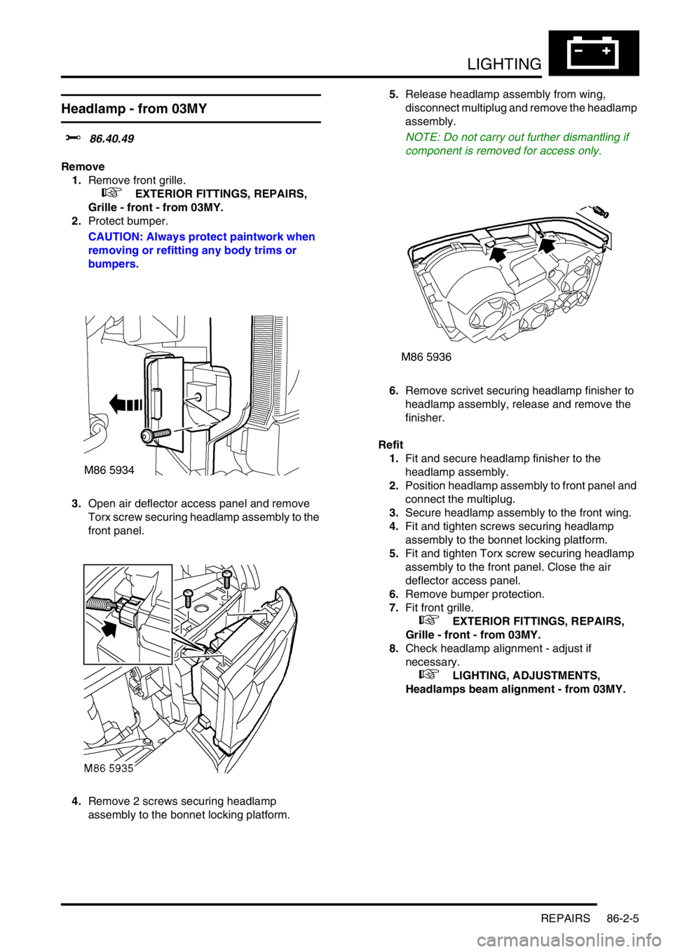
Headlamp - from 03MY
$% 86.40.49
Remove
1.Remove front grille.
+ EXTERIOR FITTINGS, REPAIRS,
Grille - front - from 03MY.
2.Protect bumper.
CAUTION: Always protect paintwork when
removing or refitting any body trims or
bumpers.
3.Open air deflector access panel and remove
Torx screw securing headlamp assembly to the
front panel.
4.Remove 2 screws securing headlamp
assembly to the bonnet locking platform.5.Release headlamp assembly from wing,
disconnect multiplug and remove the headlamp
assembly.
NOTE: Do not carry out further dismantling if
component is removed for access only.
6.Remove scrivet securing headlamp finisher to
headlamp assembly, release and remove the
finisher.
Refit
1.Fit and secure headlamp finisher to the
headlamp assembly.
2.Position headlamp assembly to front panel and
connect the multiplug.
3.Secure headlamp assembly to the front wing.
4.Fit and tighten screws securing headlamp
assembly to the bonnet locking platform.
5.Fit and tighten Torx screw securing headlamp
assembly to the front panel. Close the air
deflector access panel.
6.Remove bumper protection.
7.Fit front grille.
+ EXTERIOR FITTINGS, REPAIRS,
Grille - front - from 03MY.
8.Check headlamp alignment - adjust if
necessary.
+ LIGHTING, ADJUSTMENTS,
Headlamps beam alignment - from 03MY.
Page 1282 of 1529
LIGHTING
REPAIRS 86-2-9
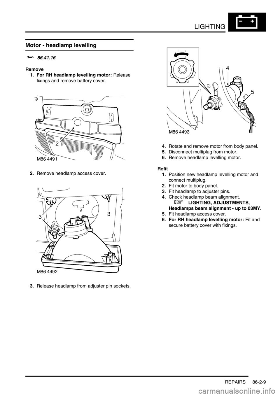
Motor - headlamp levelling
$% 86.41.16
Remove
1. For RH headlamp levelling motor: Release
fixings and remove battery cover.
2.Remove headlamp access cover.
3.Release headlamp from adjuster pin sockets. 4.Rotate and remove motor from body panel.
5.Disconnect multiplug from motor.
6.Remove headlamp levelling motor.
Refit
1.Position new headlamp levelling motor and
connect multiplug.
2.Fit motor to body panel.
3.Fit headlamp to adjuster pins.
4.Check headlamp beam alignment.
+ LIGHTING, ADJUSTMENTS,
Headlamps beam alignment - up to 03MY.
5.Fit headlamp access cover.
6. For RH headlamp levelling motor: Fit and
secure battery cover with fixings.
Page 1290 of 1529
BODY CONTROL UNIT
DESCRIPTION AND OPERATION 86-3-3
BCU outputs
The BCU processes the input signals it receives and uses the information to determine the control outputs that need
to be established for any given set of conditions. The BCU provides controlled outputs for the following systems:
lInterior courtesy lamps.
lFuel flap release actuator.
lAnti-theft status LED.
lEngine Control Module.
lDoor lock actuators.
lDirection indicators and hazard warning lamps.
lHeadlamps.
lAlarm sounder.
lVehicle horns.
lBattery backed sounder.
lStarter relay.
lPassive re-mobilisation exciter coil.
Simultaneous switching of outputs in different units is limited by the bus transfer time, but the skew is no longer than
100 ms for either the BCU or the IDM. When the processor is reset, all outputs are switched off until the inputs have
been read for the first time to check current condition.
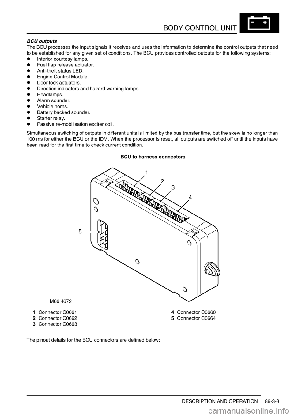
BCU to harness connectors
1Connector C0661
2Connector C0662
3Connector C06634Connector C0660
5Connector C0664
The pinout details for the BCU connectors are defined below:
Page 1293 of 1529
BODY CONTROL UNIT
86-3-6 DESCRIPTION AND OPERATION
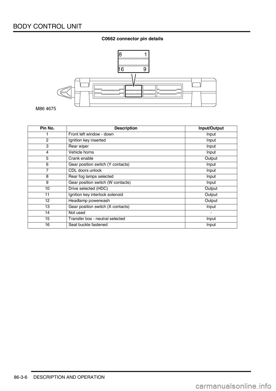
C0662 connector pin details
Pin No. Description Input/Output
1 Front left window - down Input
2 Ignition key inserted Input
3 Rear wiper Input
4 Vehicle horns Input
5 Crank enable Output
6 Gear position switch (Y contacts) Input
7 CDL doors unlock Input
8 Rear fog lamps selected Input
9 Gear position switch (W contacts) Input
10 Drive selected (HDC) Output
11 Ignition key interlock solenoid Output
12 Headlamp powerwash Output
13 Gear position switch (X contacts) Input
14 Not used -
15 Transfer box - neutral selected Input
16 Seat buckle fastened Input