check engine LAND ROVER DISCOVERY 1999 Manual Online
[x] Cancel search | Manufacturer: LAND ROVER, Model Year: 1999, Model line: DISCOVERY, Model: LAND ROVER DISCOVERY 1999Pages: 1529, PDF Size: 34.8 MB
Page 711 of 1529
STEERING
57-18 ADJUSTMENTS
Hydraulic system - bleed
$% 57.15.02
Bleed
1.Clean PAS fluid reservoir around filler cap and
fluid level indicators.
2.Remove filler cap from PAS fluid reservoir. If
necessary, fill PAS fluid reservoir to upper level
indicator with recommended fluid.
+ CAPACITIES, FLUIDS,
LUBRICANTS AND SEALANTS, Fluids.
CAUTION: Ensure no dirt is allowed to enter
the steering reservoir when the cap is
removed.
3.Start engine and run to normal operating
temperature.
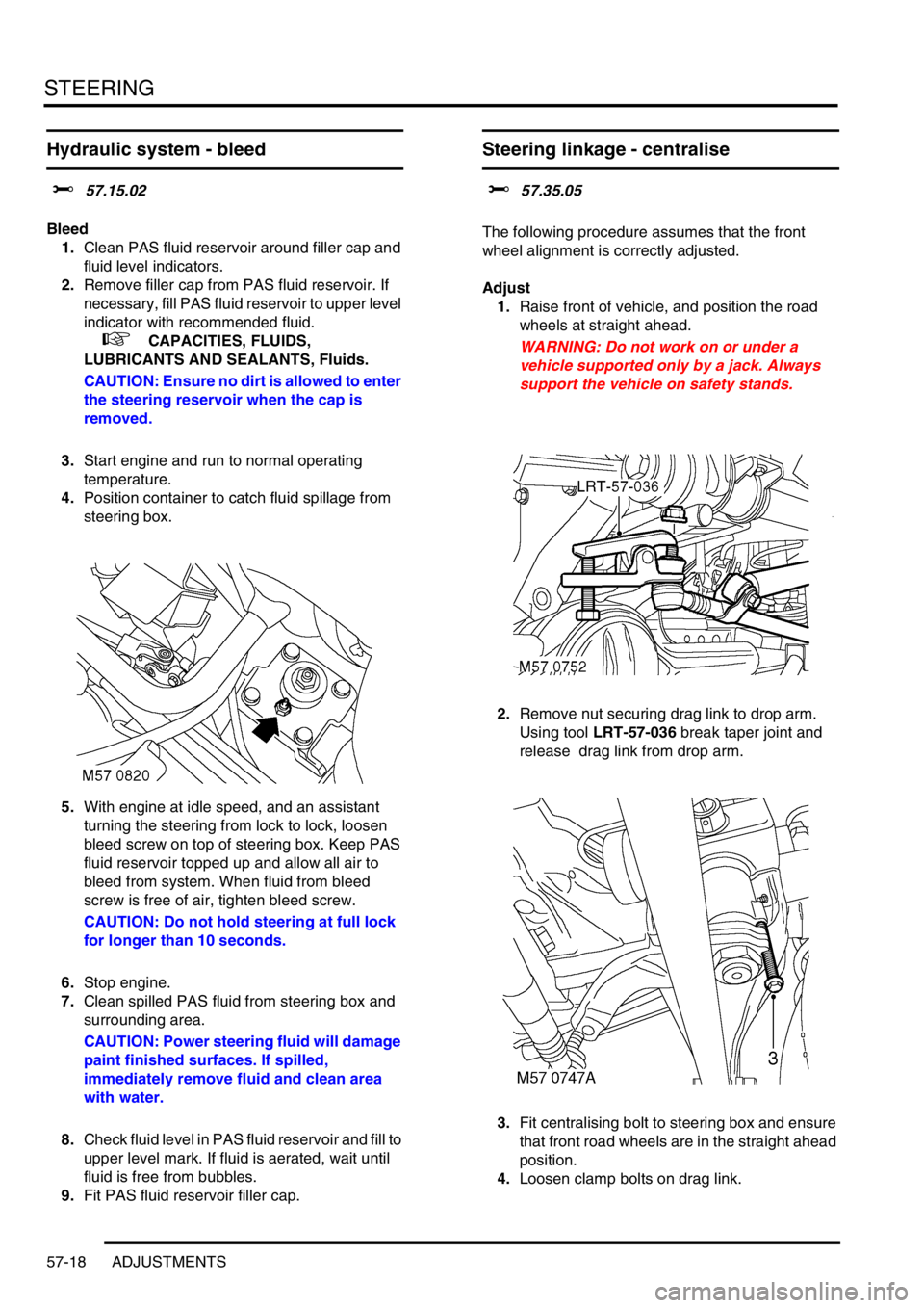
4.Position container to catch fluid spillage from
steering box.
5.With engine at idle speed, and an assistant
turning the steering from lock to lock, loosen
bleed screw on top of steering box. Keep PAS
fluid reservoir topped up and allow all air to
bleed from system. When fluid from bleed
screw is free of air, tighten bleed screw.
CAUTION: Do not hold steering at full lock
for longer than 10 seconds.
6.Stop engine.
7.Clean spilled PAS fluid from steering box and
surrounding area.
CAUTION: Power steering fluid will damage
paint finished surfaces. If spilled,
immediately remove fluid and clean area
with water.
8.Check fluid level in PAS fluid reservoir and fill to
upper level mark. If fluid is aerated, wait until
fluid is free from bubbles.
9.Fit PAS fluid reservoir filler cap.
Steering linkage - centralise
$% 57.35.05
The following procedure assumes that the front
wheel alignment is correctly adjusted.
Adjust
1.Raise front of vehicle, and position the road
wheels at straight ahead.
WARNING: Do not work on or under a
vehicle supported only by a jack. Always
support the vehicle on safety stands.
2.Remove nut securing drag link to drop arm.
Using tool LRT-57-036 break taper joint and
release drag link from drop arm.
3.Fit centralising bolt to steering box and ensure
that front road wheels are in the straight ahead
position.
4.Loosen clamp bolts on drag link.
Page 713 of 1529
STEERING
57-20 ADJUSTMENTS
Power steering pressure check - diesel
models
$% 57.90.10.01
Check
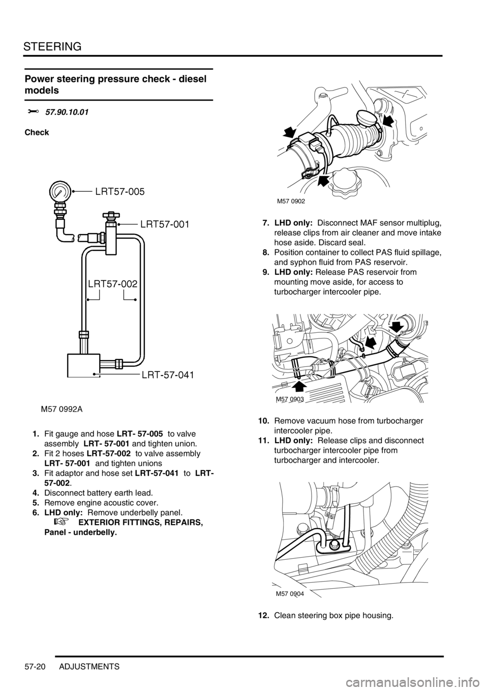
1.Fit gauge and hose LRT- 57-005 to valve
assembly LRT- 57-001 and tighten union.
2.Fit 2 hoses LRT-57-002 to valve assembly
LRT- 57-001 and tighten unions
3.Fit adaptor and hose set LRT-57-041 to LRT-
57-002.
4.Disconnect battery earth lead.
5.Remove engine acoustic cover.
6. LHD only: Remove underbelly panel.
+ EXTERIOR FITTINGS, REPAIRS,
Panel - underbelly.7. LHD only: Disconnect MAF sensor multiplug,
release clips from air cleaner and move intake
hose aside. Discard seal.
8.Position container to collect PAS fluid spillage,
and syphon fluid from PAS reservoir.
9. LHD only: Release PAS reservoir from
mounting move aside, for access to
turbocharger intercooler pipe.
10.Remove vacuum hose from turbocharger
intercooler pipe.
11. LHD only: Release clips and disconnect
turbocharger intercooler pipe from
turbocharger and intercooler.
12.Clean steering box pipe housing.
M57 0902
M57 0903
M57 0904
Page 714 of 1529
STEERING
ADJUSTMENTS 57-21
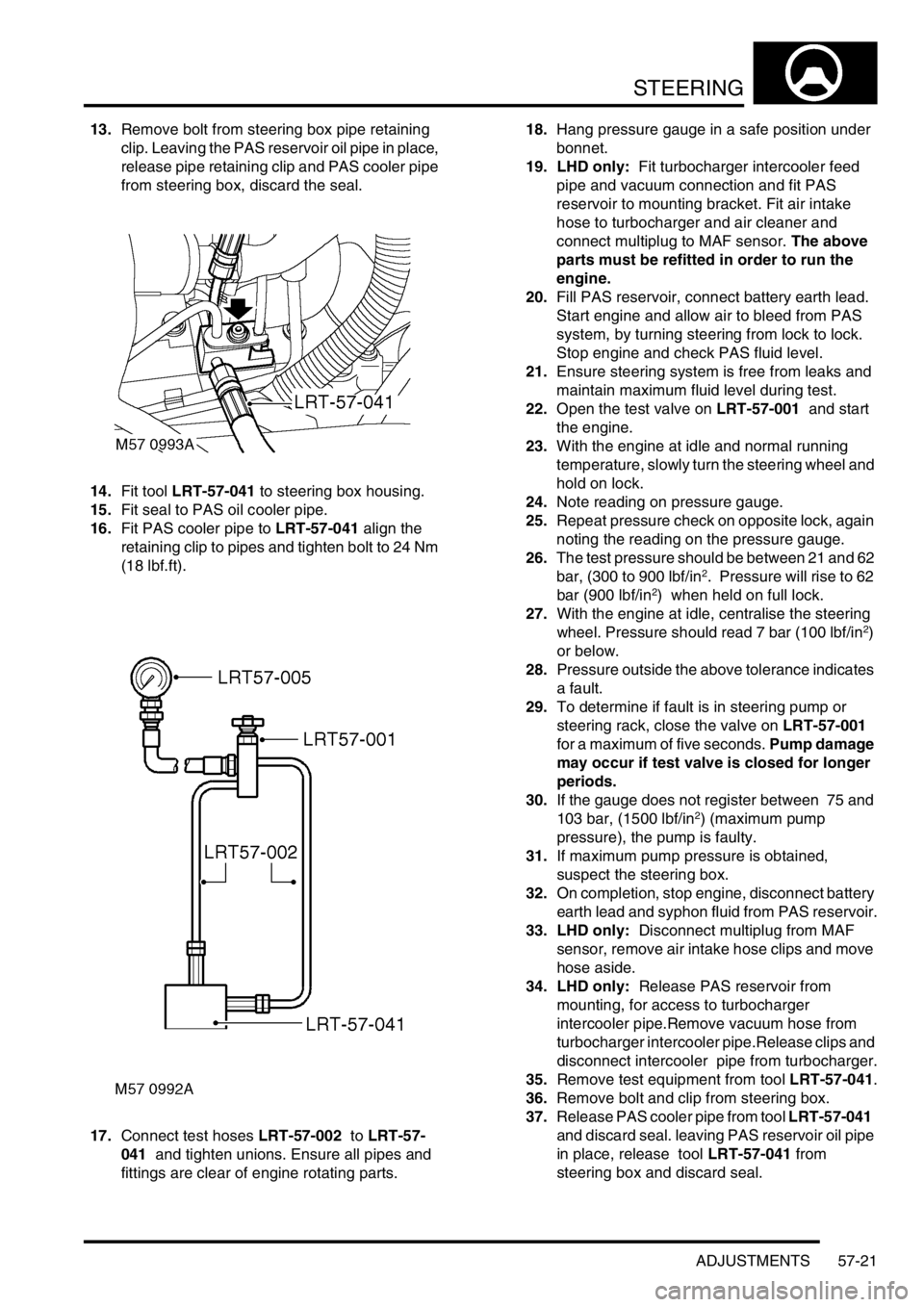
13.Remove bolt from steering box pipe retaining
clip. Leaving the PAS reservoir oil pipe in place,
release pipe retaining clip and PAS cooler pipe
from steering box, discard the seal.
14.Fit tool LRT-57-041 to steering box housing.
15.Fit seal to PAS oil cooler pipe.
16.Fit PAS cooler pipe to LRT-57-041 align the
retaining clip to pipes and tighten bolt to 24 Nm
(18 lbf.ft).
17.Connect test hoses LRT-57-002 to LRT-57-
041 and tighten unions. Ensure all pipes and
fittings are clear of engine rotating parts.18.Hang pressure gauge in a safe position under
bonnet.
19. LHD only: Fit turbocharger intercooler feed
pipe and vacuum connection and fit PAS
reservoir to mounting bracket. Fit air intake
hose to turbocharger and air cleaner and
connect multiplug to MAF sensor. The above
parts must be refitted in order to run the
engine.
20.Fill PAS reservoir, connect battery earth lead.
Start engine and allow air to bleed from PAS
system, by turning steering from lock to lock.
Stop engine and check PAS fluid level.
21.Ensure steering system is free from leaks and
maintain maximum fluid level during test.
22.Open the test valve on LRT-57-001 and start
the engine.
23.With the engine at idle and normal running
temperature, slowly turn the steering wheel and
hold on lock.
24.Note reading on pressure gauge.
25.Repeat pressure check on opposite lock, again
noting the reading on the pressure gauge.
26.The test pressure should be between 21 and 62
bar, (300 to 900 lbf/in
2. Pressure will rise to 62
bar (900 lbf/in2) when held on full lock.
27.With the engine at idle, centralise the steering
wheel. Pressure should read 7 bar (100 lbf/in
2)
or below.
28.Pressure outside the above tolerance indicates
a fault.
29.To determine if fault is in steering pump or
steering rack, close the valve on LRT-57-001
for a maximum of five seconds. Pump damage
may occur if test valve is closed for longer
periods.
30.If the gauge does not register between 75 and
103 bar, (1500 lbf/in
2) (maximum pump
pressure), the pump is faulty.
31.If maximum pump pressure is obtained,
suspect the steering box.
32.On completion, stop engine, disconnect battery
earth lead and syphon fluid from PAS reservoir.
33. LHD only: Disconnect multiplug from MAF
sensor, remove air intake hose clips and move
hose aside.
34. LHD only: Release PAS reservoir from
mounting, for access to turbocharger
intercooler pipe.Remove vacuum hose from
turbocharger intercooler pipe.Release clips and
disconnect intercooler pipe from turbocharger.
35.Remove test equipment from tool LRT-57-041.
36.Remove bolt and clip from steering box.
37.Release PAS cooler pipe from tool LRT-57-041
and discard seal. leaving PAS reservoir oil pipe
in place, release tool LRT-57-041 from
steering box and discard seal.
Page 716 of 1529

STEERING
ADJUSTMENTS 57-23
9.Release clips and remove air intake hose from
air cleaner housing.
Note: Pre 03 MY air intake hose illustrated.
10.Discard intake 'O' ring and move intake aside
for access.
11.Loosen union securing high pressure pipe to
PAS pump and release pipe.12.Fit adaptor LRT-57-034A to high pressure port
of PAS pump.
13.Fit adaptor LRT-57-035 to existing high
pressure hose.
14.Fit hose LRT-57-002/3 to each adaptor.
15.Fit pressure gauge LRT-57-005 to test valve
LRT-57-001
16.Connect hoses LRT-57-002/3 to LRT-57-001
and tighten unions.
17.Hang pressure gauge in a safe position under
bonnet.
18.Remove PAS reservoir filler cap, fill to level
indicator and refit cap.
19.Connect battery earth lead.
20.Start engine and allow air to bleed from PAS
system by turning steering from lock to lock.
Stop engine and check PAS fluid level.
21.Ensure steering system and test equipment are
free from leaks.
22.Maintain maximum fluid level during test.
23.Open the test valve on LRT-57-001 and start
the engine.
24.With the engine at idle, slowly turn the steering
wheel and hold on full lock.
25.Note the pressure reading on LRT-57-005.
26.Repeat the pressure check for the opposite full
lock.
27.Test pressure should be between 21 and 62
bar, (300 to 900) psi. Dependant on road
surface.
28.With the engine at idle, centralise the steering
wheel. Pressure should read 7 bar (100 psi) or
below.
29.Pressures outside the above tolerance
indicates a fault.
30.To determine if fault is in steering pump or
steering box, close the valve on LRT-57-001 for
a maximum of 5 seconds. Pump damage may
occur if test valve is closed for longer periods.
31.If gauge does not register between 75 and 103
bar, (1500 psi), (maximum pump pressure), the
pump is faulty.
32.If maximum pump pressure is correct suspect
the steering box.
Page 717 of 1529
STEERING
57-24 ADJUSTMENTS
33.On completion stop engine, disconnect battery
earth lead and syphon fluid from PAS reservoir.
34.Remove test equipment from LRT-57-002.
35.Clean PAS pump and pipe union.
36.Fit new 'O' ring to high pressure pipe, align to
PAS pump and tighten union to 25 Nm (18
lbf.ft).
37.Secure PAS pipes in clip.
38.Using new 'O' ring fit intake hose to air cleaner
and secure clips.
39.Remove PAS reservoir filler cap, fill to level
indicator and refit cap.
40.Connect battery earth lead.
41.Start engine and allow air to bleed from PAS
system, by turning steering from lock to lock.
42.Visually check PAS system for leaks.
43.Clean chassis member.
44.Check power steering fluid, if aerated, wait until
fluid is free from bubbles then top-up reservoir
to 'UPPER' level mark.
45.Lower vehicle.
46.Dismantle test equipment.
Power steering pressure check - V8 RHD
models
$% 57.90.10.01
Check
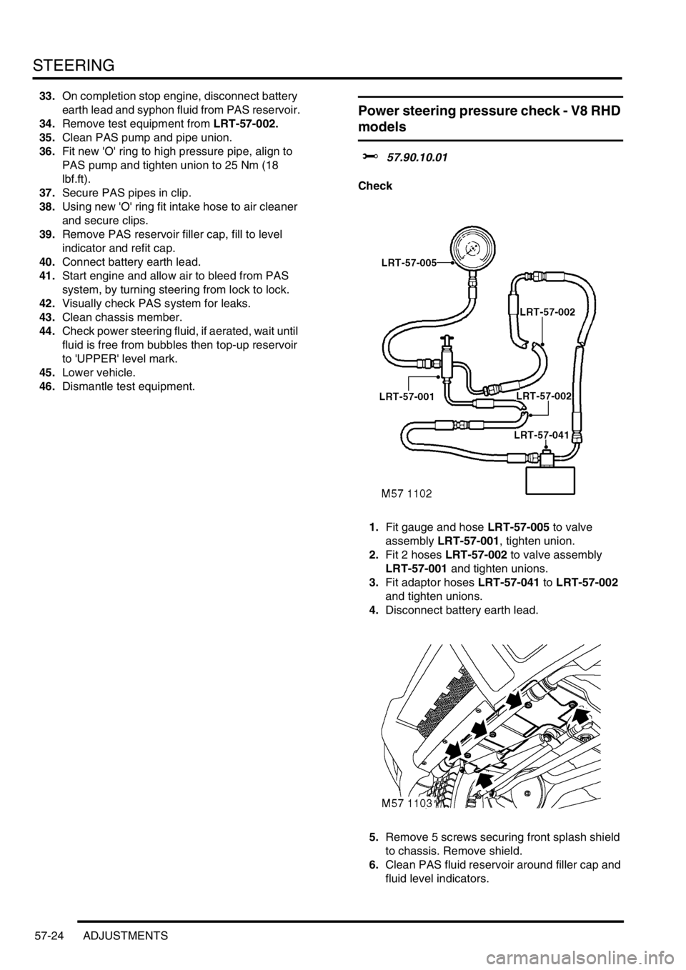
1.Fit gauge and hose LRT-57-005 to valve
assembly LRT-57-001, tighten union.
2.Fit 2 hoses LRT-57-002 to valve assembly
LRT-57-001 and tighten unions.
3.Fit adaptor hoses LRT-57-041 to LRT-57-002
and tighten unions.
4.Disconnect battery earth lead.
5.Remove 5 screws securing front splash shield
to chassis. Remove shield.
6.Clean PAS fluid reservoir around filler cap and
fluid level indicators.
Page 718 of 1529
STEERING
ADJUSTMENTS 57-25
7.Syphon PAS fluid from reservoir.
8.Position container to collect PAS fluid spillage.
9.Clean steering box pipe pipe housing.
10.Remove bolt securing pipe clip to steering box.
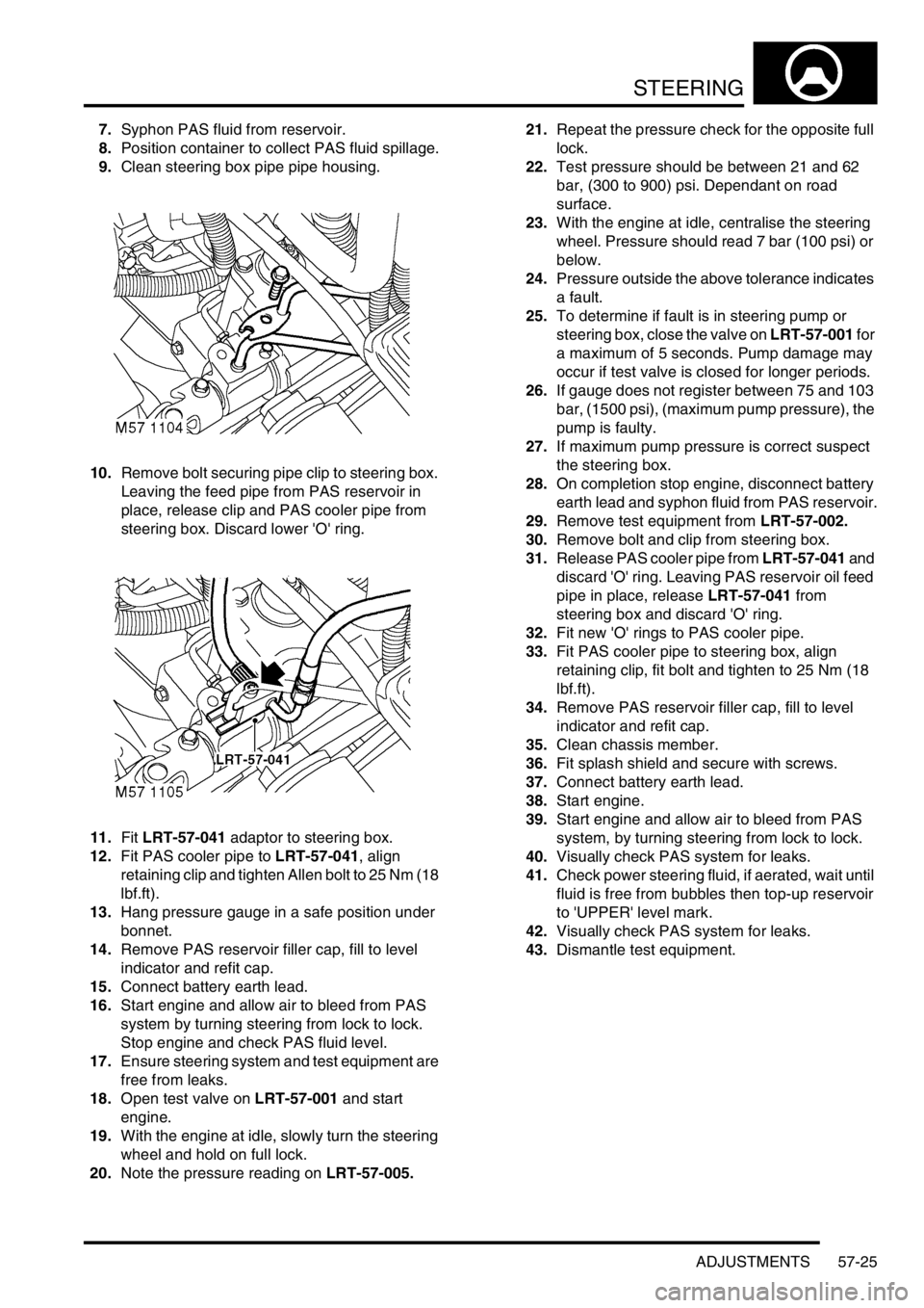
Leaving the feed pipe from PAS reservoir in
place, release clip and PAS cooler pipe from
steering box. Discard lower 'O' ring.
11.Fit LRT-57-041 adaptor to steering box.
12.Fit PAS cooler pipe to LRT-57-041, align
retaining clip and tighten Allen bolt to 25 Nm (18
lbf.ft).
13.Hang pressure gauge in a safe position under
bonnet.
14.Remove PAS reservoir filler cap, fill to level
indicator and refit cap.
15.Connect battery earth lead.
16.Start engine and allow air to bleed from PAS
system by turning steering from lock to lock.
Stop engine and check PAS fluid level.
17.Ensure steering system and test equipment are
free from leaks.
18.Open test valve on LRT-57-001 and start
engine.
19.With the engine at idle, slowly turn the steering
wheel and hold on full lock.
20.Note the pressure reading on LRT-57-005.21.Repeat the pressure check for the opposite full
lock.
22.Test pressure should be between 21 and 62
bar, (300 to 900) psi. Dependant on road
surface.
23.With the engine at idle, centralise the steering
wheel. Pressure should read 7 bar (100 psi) or
below.
24.Pressure outside the above tolerance indicates
a fault.
25.To determine if fault is in steering pump or
steering box, close the valve on LRT-57-001 for
a maximum of 5 seconds. Pump damage may
occur if test valve is closed for longer periods.
26.If gauge does not register between 75 and 103
bar, (1500 psi), (maximum pump pressure), the
pump is faulty.
27.If maximum pump pressure is correct suspect
the steering box.
28.On completion stop engine, disconnect battery
earth lead and syphon fluid from PAS reservoir.
29.Remove test equipment from LRT-57-002.
30.Remove bolt and clip from steering box.
31.Release PAS cooler pipe from LRT-57-041 and
discard 'O' ring. Leaving PAS reservoir oil feed
pipe in place, release LRT-57-041 from
steering box and discard 'O' ring.
32.Fit new 'O' rings to PAS cooler pipe.
33.Fit PAS cooler pipe to steering box, align
retaining clip, fit bolt and tighten to 25 Nm (18
lbf.ft).
34.Remove PAS reservoir filler cap, fill to level
indicator and refit cap.
35.Clean chassis member.
36.Fit splash shield and secure with screws.
37.Connect battery earth lead.
38.Start engine.
39.Start engine and allow air to bleed from PAS
system, by turning steering from lock to lock.
40.Visually check PAS system for leaks.
41.Check power steering fluid, if aerated, wait until
fluid is free from bubbles then top-up reservoir
to 'UPPER' level mark.
42.Visually check PAS system for leaks.
43.Dismantle test equipment.
Page 722 of 1529

STEERING
REPAIRS 57-29
12. RH drive models with ACE: Position ACE
control arms to access steering box bolts.
13.With assistance remove 4 securing bolts and
remove steering box.
14.Remove centralising bolt from steering box. Refit
1.Fit centralising bolt to steering box.
2. With assistance, position steering box, fit bolts
and tighten to 90 Nm (66 lbf.ft).
3. RH drive models with ACE: Ensure washer is
in place on lower ball joint of anti-roll bar link,
then connect lower ball joint to axle. Tighten nut
to 100 Nm (74 lbf.ft).
4.Position drag link, fit nut and tighten to 80 Nm
(59 lbf.ft).
5.Position Panhard rod, fit bolt and nut and
tighten to 230 Nm (170 lbf.ft).
6.Clean PAS pipe ends and 'O' ring recess.
7.Lubricate new 'O' rings for PAS pipes with clean
PAS fluid.
8.Fit 'O' rings to PAS pipes and position pipes in
steering box. Fit PAS pipe bracket and tighten
bolt to 22 Nm (16 lbf.ft).
9. RHD models: Fit oil filter and housing:
lClean oil filter housing and engine mating
faces.
lLubricate new 'O' ring with clean engine oil
and fit to housing.
lPosition oil filter housing and tighten bolts to
9 Nm (7 lbf.ft).
10.Ensure steering wheel is centralised. Fit
universal joint between steering box and
intermediate shaft and tighten bolts to 25 Nm
(18 lbf.ft).
11.Remove centralising bolt from steering box.
12.Fit road wheel(s) and tighten nuts to 140 Nm
(103 lbf.ft)..
13.Remove stand(s) and lower vehicle.
14.Check and top up engine oil.
15.Bleed PAS system.
+ STEERING, ADJUSTMENTS,
Hydraulic system - bleed.
16.Centralise steering linkage
+ STEERING, ADJUSTMENTS,
Steering linkage - centralise.
Page 756 of 1529

FRONT SUSPENSION
DESCRIPTION AND OPERATION 60-11
The ACE system uses a semi-synthetic hydraulic fluid which is the same as the fluid used for the PAS system. The
total capacity of the ACE system is 1.62 litres (0.42 US Gallons).
CAUTION: The ACE hydraulic system is extremely sensitive to the ingress of dirt or debris. The smallest
amount could render the system unserviceable. It is imperative that the following precautions are taken.
lACE components are thoroughly cleaned externally before work commences;
lall opened pipe and module ports are capped immediately;
lall fluid is stored in and administered through clean containers.
In the event of an ECU or hydraulic failure the system will fail safe to a 'locked bars' condition. The 'locked bars'
condition will allow the torsion bars to operate in a similar manner as conventional 'passive' anti-roll bars. Prolonged
cornering forces will allow a progressive increase in roll angle due to hydraulic leakage through the actuators and
valve block. Failures will be relayed to the driver by the illumination of the ACE warning lamp in the instrument pack.
Faults are recorded by the ECU and can be retrieved using TestBook.
When the ignition switch is moved to position II, the warning lamp will illuminate for two seconds to check functionality.
The warning lamp functionality can also be checked using TestBook.
TestBook must also be used to perform a bleeding procedure after maintenance operations have been performed to
ensure that complete system bleeding is performed. Trapped air in the system can seriously reduce the system
performance.
Fluid reservoir
The moulded plastic fluid reservoir is mounted on the left hand side of the engine compartment on a bracket which is
attached to the inner wing. The reservoir is dual purpose, being divided into two separate chambers; one for the ACE
system and one for the PAS system. Each chamber has its own filler neck and cap and is identified by moulded
lettering on the reservoir adjacent to each filler.
A non-serviceable filter assembly is fitted in the base of each chamber. The filter is made from fine stainless steel
mesh which is moulded into the body of the reservoir. The filter removes particulate matter from the fluid before it is
drawn into the hydraulic pump.
Upper and lower fluid level marks are moulded onto the reservoir body. The capacity of the ACE reservoir chamber
to the upper level mark is 0.5 litre (0.13 US Gallon).
Page 770 of 1529
FRONT SUSPENSION
ADJUSTMENTS 60-25
ADJUST ME NTS
ACE hydraulic system bleeding
$% 60.60.13
Introduction
CAUTION: The ACE hydraulic system is
extremely sensitive to the ingress of dirt or
debris. The smallest amount could render the
system unserviceable. It is imperative that the
following precautions are taken.
lACE components are thoroughly cleaned
externally before work commences;
lall opened pipe and module ports are
capped immediately;
lall fluid is stored in and administered
through clean containers.
Check
1.Check the ACE system fluid level.
+ FRONT SUSPENSION,
ADJUSTMENTS, Fluid level check - ACE
system.
Bleed
1.With vehicle on ramp, connect TestBook and
follow bleed procedure as described.
Fluid level check - ACE system
$% 60.60.14
Introduction
CAUTION: The ACE hydraulic system is
extremely sensitive to the ingress of dirt or
debris. The smallest amount could render the
system unserviceable. It is imperative that the
following precautions are taken.
lACE components are thoroughly cleaned
externally before work commences;
lall opened pipe and module ports are
capped immediately;
lall fluid is stored in and administered
through clean containers.
Check
1.Clean reservoir around fluid level marks.
2.Visually check fluid level through side of
reservoir. Fluid level must be between upper
and lower fluid level marks.
Top-up
1.Clean reservoir around filler cap.
2.Remove filler cap from reservoir and fill to
upper fluid level mark with recommended fluid.
+ CAPACITIES, FLUIDS,
LUBRICANTS AND SEALANTS, Fluids.
3.Fit filler cap to reservoir
4.Start and run engine for 2 minutes to circulate
fluid.
5.If necessary, top-up reservoir to upper fluid
level mark.
Page 792 of 1529
FRONT SUSPENSION
REPAIRS 60-47
Filter - high pressure - ACE
$% 60.60.21
CAUTION: The ACE hydraulic system is
extremely sensitive to the ingress of dirt or
debris. The smallest amount could render the
system unserviceable. It is imperative that the
following precautions are taken.
lACE components are thoroughly cleaned
externally before work commences;
lall opened pipe and module ports are
capped immediately;
lall fluid is stored in and administered
through clean containers.
Remove
1.Raise vehicle on a ramp.
2.Position container to collect fluid spillage.
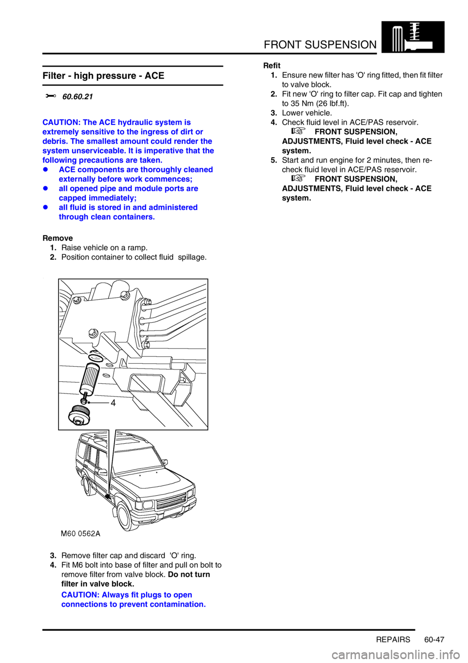
3.Remove filter cap and discard 'O' ring.
4.Fit M6 bolt into base of filter and pull on bolt to
remove filter from valve block. Do not turn
filter in valve block.
CAUTION: Always fit plugs to open
connections to prevent contamination.Refit
1.Ensure new filter has 'O' ring fitted, then fit filter
to valve block.
2.Fit new 'O' ring to filter cap. Fit cap and tighten
to 35 Nm (26 lbf.ft).
3.Lower vehicle.
4.Check fluid level in ACE/PAS reservoir.
+ FRONT SUSPENSION,
ADJUSTMENTS, Fluid level check - ACE
system.
5.Start and run engine for 2 minutes, then re-
check fluid level in ACE/PAS reservoir.
+ FRONT SUSPENSION,
ADJUSTMENTS, Fluid level check - ACE
system.