ecm LAND ROVER DISCOVERY 2002 Workshop Manual
[x] Cancel search | Manufacturer: LAND ROVER, Model Year: 2002, Model line: DISCOVERY, Model: LAND ROVER DISCOVERY 2002Pages: 1672, PDF Size: 46.1 MB
Page 1016 of 1672

REAR SUSPENSION
DESCRIPTION AND OPERATION 64-11
1Battery supply (via SLABS relay)
2Ignition supply
3RH height sensor
4LH height sensor
5Off-road mode warning lamp
6Audible warning speaker
7Instrument pack
8SLS warning lamp
9Fusible link 9
10SLS relay
11Air supply unit12RH air valve
13LH air valve
14Exhaust valve
15Diagnostic socket
16Off-road mode switch
17SLS remote handset
18Body Control Unit (BCU)
19Door switches
20SLABS ECU
21Engine Control Module (ECM)
Page 1063 of 1672

BRAKES
70-18 DESCRIPTION AND OPERATION
The SLABS ECU continually calculates vehicle speed using the wheel speed inputs from all four ABS sensors. The
calculated vehicle speed is then used as a reference against which individual wheel speeds are monitored for
unacceptable acceleration or deceleration. The ABS sensor inputs are also used by the SLABS ECU to detect vehicle
deceleration rate, vehicle cornering rate and rough terrain.
The engaged forward gear and (on manual gearbox models) the clutch status are computed from the engine data
input, the engine speed input and vehicle speed. Reverse gear status is provided by an input from the reverse lamp
switch (manual gearbox models) or the BCU (automatic gearbox models). On automatic models, the BCU also
provides the neutral selected input.
In addition to controlling the brake related functions, the SLABS ECU:
lControls the operation of the self levelling suspension (SLS) system (where fitted).
+ REAR SUSPENSION, DESCRIPTION AND OPERATION, Description.
lOn V8 models, outputs a rough road signal to the ECM when traversing rough terrain.
lOutputs a vehicle speed signal.
The vehicle speed signal is output to the following systems (where fitted):
lActive Cornering Enhancement.
+ FRONT SUSPENSION, DESCRIPTION AND OPERATION, Description - ACE.
lAir conditioning.
+ AIR CONDITIONING, DESCRIPTION AND OPERATION, Description.
lCruise control.
+ ENGINE MANAGEMENT SYSTEM - Td5, DESCRIPTION AND OPERATION, Description.
+ ENGINE MANAGEMENT SYSTEM - V8, DESCRIPTION AND OPERATION, Description - engine
management.
lEngine management.
+ ENGINE MANAGEMENT SYSTEM - Td5, DESCRIPTION AND OPERATION, Description.
+ ENGINE MANAGEMENT SYSTEM - V8, DESCRIPTION AND OPERATION, Description - engine
management.
lIn-car entertainment.
+ IN CAR ENTERTAINMENT, DESCRIPTION AND OPERATION, Description.
lInstrument pack.
+ INSTRUMENTS, DESCRIPTION AND OPERATION, Description.
ABS sensors
The ABS sensors supply the SLABS ECU with a sinusoidal speed signal from each wheel. An inductive sensor,
installed in the hub bearing of each wheel, senses off a 60 tooth exciter ring integrated into the inner race of the hub
bearing. Each ABS sensor has a fly-lead connecting it to the vehicle wiring.
6 Shuttle valve switches Input
7 Rear left outlet solenoid valve Output
8 Rear left inlet solenoid valve Output
9 Centre differential lock switch Input
10 Rear right outlet solenoid valve Output
11 Rear right inlet solenoid valve Output
12 Brake lamp relay Output
15 Return pump relay Output
C0655
7 Audible warning Output
10 Engine speed Input
Connector and pins not listed are either not used or used by the self levelling suspension system.
+ REAR SUSPENSION, DESCRIPTION AND OPERATION, Description.
Connector/Pin No. Description Input/Output
Page 1283 of 1672

PANEL REPAIRS
77-2-34 REPAIRS
Refit
1.Fit windscreen side finisher.
+ EXTERIOR FITTINGS, REPAIRS,
Side finisher - windscreen.
2.Fit insulation pad to engine bulkhead.
3.Fit front mud flap.
4.Fit road wheel and tighten nuts to 140 Nm (103
lbf.ft).
5.Fit wiring harness to valance assembly.
6. Models with A/C: Fit A/C pipes to valance
assembly.
7.Fit PAS/ACE reservoir.
8.Fit brake pipes to valance assembly.
9. LHD models: Fit brake servo.
+ BRAKES, REPAIRS, Servo - brake.
10.Fit ABS modulator unit.
+ BRAKES, REPAIRS, Modulator unit
- ABS.
11.Fit front bulkhead assembly.
+ PANEL REPAIRS, REPAIRS, Front
bulkhead assembly.
12.Connect leads/multiplug to alternator.
13.Connect battery leads, negative lead last.
'A' post assembly
In this procedure, the front wing and the valance
outer reinforcement (rear section) are replaced in
conjunction with the 'A' post assembly. The dash side
assembly can also be replaced in this procedure if
required.
Remove
1.Disconnect both battery leads, negative lead
first.
2.Disconnect leads/multiplug from alternator.
3.Remove bonnet.
4.Remove front wing.
+ EXTERIOR FITTINGS, REPAIRS,
Wing - front - up to 03MY.
5.Remove RH or LH front door.
+ DOORS, REPAIRS, Door - front.
6.Remove RH or LH sill finisher.
7.Remove windscreen.
+ SCREENS, REPAIRS, Windscreen.
8. Diesel models: Remove ECM.
+ ENGINE MANAGEMENT SYSTEM -
Td5, REPAIRS, Engine control module
(ECM).
9.Remove RH or LH 'A' post inner finishers and
disconnect speaker multiplug (if fitted).
10.Release sunroof drain tube and position aside.
11.Remove RH or LH front seat.
+ SEATS, REPAIRS, Seat - front.
12. RH side: Remove CD autochanger.
+ IN CAR ENTERTAINMENT,
REPAIRS, CD autochanger.
13.Remove fascia.
+ INTERIOR TRIM COMPONENTS,
REPAIRS, Fascia.
14. Driver's side: Remove steering column
support bracket.
15.Remove relevant wiring from 'A' post.
16.Remove tread plate from front door aperture.
17.Release front carpet and position aside.
18.Remove front door aperture seal.
19.Remove engine bulkhead insulation.
Page 1284 of 1672
PANEL REPAIRS
REPAIRS 77-2-35
Repair
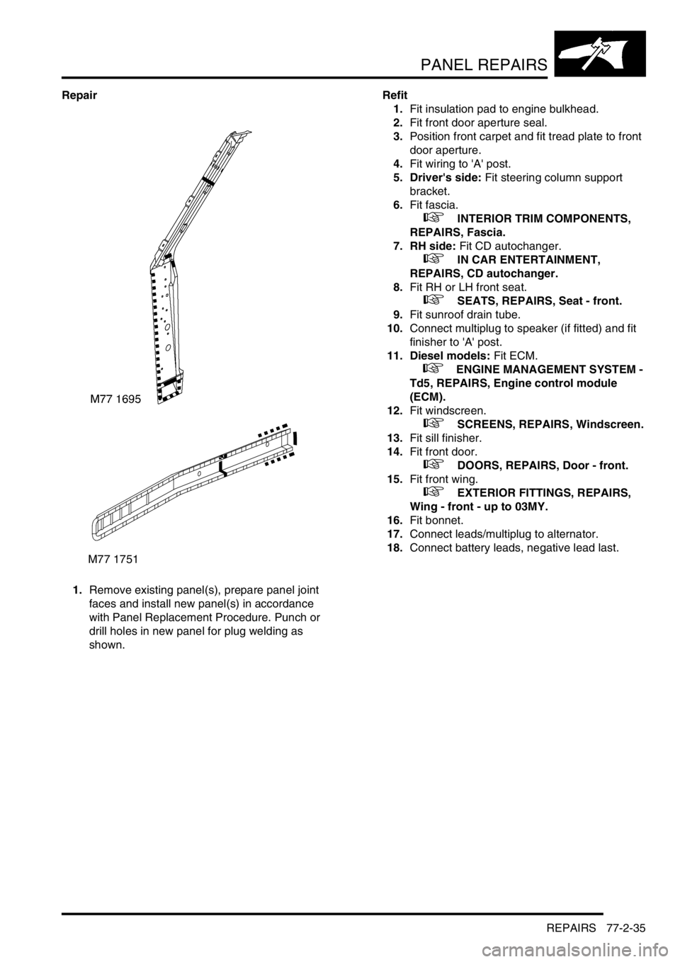
1.Remove existing panel(s), prepare panel joint
faces and install new panel(s) in accordance
with Panel Replacement Procedure. Punch or
drill holes in new panel for plug welding as
shown.Refit
1.Fit insulation pad to engine bulkhead.
2.Fit front door aperture seal.
3.Position front carpet and fit tread plate to front
door aperture.
4.Fit wiring to 'A' post.
5. Driver's side: Fit steering column support
bracket.
6.Fit fascia.
+ INTERIOR TRIM COMPONENTS,
REPAIRS, Fascia.
7. RH side: Fit CD autochanger.
+ IN CAR ENTERTAINMENT,
REPAIRS, CD autochanger.
8.Fit RH or LH front seat.
+ SEATS, REPAIRS, Seat - front.
9.Fit sunroof drain tube.
10.Connect multiplug to speaker (if fitted) and fit
finisher to 'A' post.
11. Diesel models: Fit ECM.
+ ENGINE MANAGEMENT SYSTEM -
Td5, REPAIRS, Engine control module
(ECM).
12.Fit windscreen.
+ SCREENS, REPAIRS, Windscreen.
13.Fit sill finisher.
14.Fit front door.
+ DOORS, REPAIRS, Door - front.
15.Fit front wing.
+ EXTERIOR FITTINGS, REPAIRS,
Wing - front - up to 03MY.
16.Fit bonnet.
17.Connect leads/multiplug to alternator.
18.Connect battery leads, negative lead last.
M77 1751
Page 1378 of 1672

AIR CONDITIONING
DESCRIPTION AND OPERATION 82-5
To accomplish the transfer of heat, the refrigerant is circulated around the system, where it passes through two
pressure/temperature regimes. In each of the pressure/temperature regimes, the refrigerant changes state, during
which process maximum heat absorption or release occurs. The low pressure/temperature regime is from the
thermostatic expansion valve, through the evaporator to the compressor; the refrigerant decreases in pressure and
temperature at the thermostatic expansion valve, then changes state from liquid to vapour in the evaporator, to absorb
heat. The high pressure/temperature regime is from the compressor, through the condenser and receiver drier to the
thermostatic expansion valve; the refrigerant increases in pressure and temperature as it passes through the
compressor, then releases heat and changes state from vapour to liquid in the condenser.
Compressor
1Pulley
2Inlet connection
3Outlet connection
4Pressure relief valve
5Clutch connector
The compressor circulates the refrigerant around the system by compressing low pressure, low temperature vapour
from the evaporator and discharging the resultant high pressure, high temperature vapour to the condenser.
The compressor is attached to a mounting bracket on the engine, and is a ten cylinder swash plate unit with a fixed
displacement of 177 ml/rev (0.19 US qt/rev). The auxiliary drive belt drives the compressor via a pulley and an
electrically actuated clutch. Operation of the clutch is controlled by the Engine Control Module (ECM).
To protect the refrigerant system from unacceptably high pressure, a pressure relief valve is installed in the outlet side
of the compressor. The pressure relief valve is set to operate at 34.3 to 41.4 bars (497 to 600 lbf.in
2) and vents excess
pressure into the engine compartment.
Page 1393 of 1672

AIR CONDITIONING
82-20DESCRIPTION AND OPERATION
Air distribution control
To control the air distribution within the cabin the ATC ECU signals the servo motor controlling the distribution flaps
in the heater assembly to move to the flaps to the appropriate position.
In the automatic and economy modes, if the LH or RH temperature selections are set to LO or HI, air distribution is
fixed as follows:
lIf one is set to LO and one is set to a specific temperature, to face level only.
lIf one is set to HI and one is set to a specific temperature, to footwells only.
lIf one is set to LO and one is set to HI, to face level and footwells.
When specific LH and RH temperature selections are set, air distribution is determined from the target air outlet
temperatures. For higher target air outlet temperatures, air distribution is set to footwells only. For lower target air
outlet temperatures, air distribution is set to face level only. For intermediate target air outlet temperatures, air
distribution is set to face level and footwells. When the air distribution is set to face level and footwells, the ATC ECU
varies the bias between the footwells and the face level outlets, in three stages, to provide a gradual transition of air
distribution from footwells only to face level only. The three stages of bias are also employed when the air distribution
is manually selected to face level and footwells.
During warm-up, the air distribution changes to face level and footwells for a period, then reverts to footwells only.
The period of air distribution at face level and footwells can be cancelled by pressing and holding the on/off and defrost
mode switches, then turning the ignition switch from off to on. Pressing and holding the AUTO and defrost switches,
then turning the ignition switch from off to on, restores the period of air distribution at face level and footwells.
Compressor control
To engage the compressor clutch, the ATC ECU outputs a compressor clutch request to the ECM, which then
energises the A/C compressor clutch relay. Compressor operation is governed by the evaporator outlet air
temperature, at one of two settings, dependent on the amount of cooling required. When more cooling is required, the
compressor clutch request is output if evaporator outlet air temperature increases to 4
°C (39 °F) and cancelled when
it decreases to 3
°C (37 °F). When less cooling is required, the compressor clutch request is output if evaporator outlet
air temperature increases to 11
°C (52 °F) and cancelled when it decreases to 10 °C (50 °F).
Engine cooling fan control
While the A/C system is on, operation of the electric engine cooling fan, to assist refrigerant condenser operation, is
determined by a combination of vehicle speed and external air temperature. When cooling fan operation is required,
the ATC ECU outputs a cooling fan request to the ECM, which then energises the cooling fan relay. The cooling fan
request is output if vehicle speed is 80 km/h or less while the external air temperature is 28
°C (82 °F) or more. The
request is cancelled, and the cooling fan switched off, if either the vehicle speed increases to 100 km/h, or the external
air temperature decreases to 25
°C (77 °F).
Default settings
If the battery power supply to the ATC ECU is disrupted for any reason, e.g. battery disconnected, the system reverts
to default settings when the battery power supply is restored. Default settings are:
lTemperature indications in
°C (in some markets a conversion connector is fitted to the ATC ECU to change the
default temperature scale to
°F).
lLH and RH outlet temperatures of 22
°C (72 °F).
laudible warning switched on.
lWarm-up air distribution (to face level and footwells) function switched on.
lIf the system is first switched on using the A/C on/off switch, the automatic mode is engaged, regardless of the
settings in use when the battery was disconnected.
Page 1453 of 1672
CHARGING AND STARTING
86-1-4 REPAIRS
Battery
$% 86.15.01
Remove
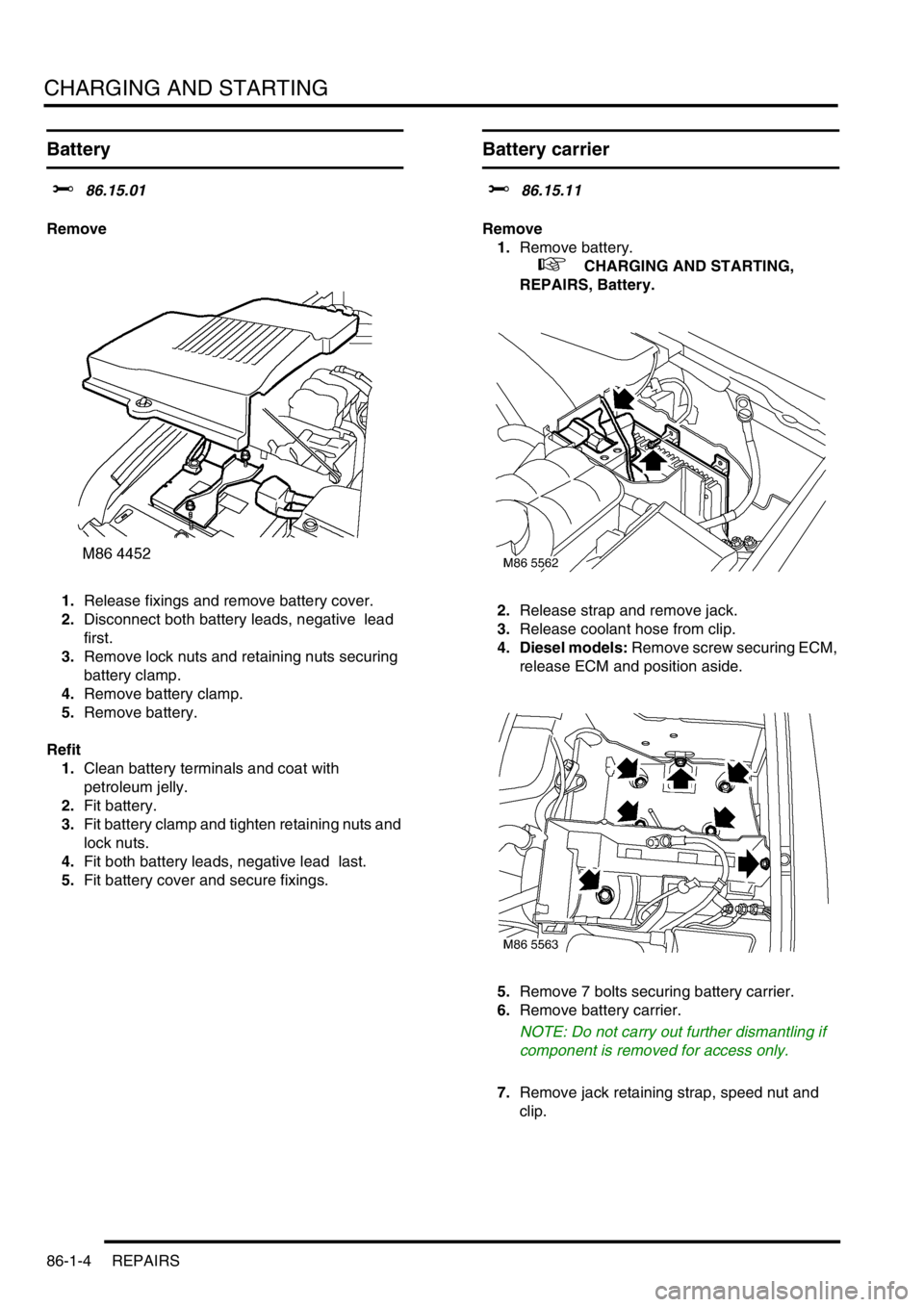
1.Release fixings and remove battery cover.
2.Disconnect both battery leads, negative lead
first.
3.Remove lock nuts and retaining nuts securing
battery clamp.
4.Remove battery clamp.
5.Remove battery.
Refit
1.Clean battery terminals and coat with
petroleum jelly.
2.Fit battery.
3.Fit battery clamp and tighten retaining nuts and
lock nuts.
4.Fit both battery leads, negative lead last.
5.Fit battery cover and secure fixings.
Battery carrier
$% 86.15.11
Remove
1.Remove battery.
+ CHARGING AND STARTING,
REPAIRS, Battery.
2.Release strap and remove jack.
3.Release coolant hose from clip.
4. Diesel models: Remove screw securing ECM,
release ECM and position aside.
5.Remove 7 bolts securing battery carrier.
6.Remove battery carrier.
NOTE: Do not carry out further dismantling if
component is removed for access only.
7.Remove jack retaining strap, speed nut and
clip.
Page 1454 of 1672

CHARGING AND STARTING
REPAIRS 86-1-5
Refit
1.Fit jack retaining strap, speed nut and clip.
2.Fit battery carrier, fit bolts and tighten to 28 Nm
(21 lbf.ft).
3. Diesel models: Fit ECM and secure with
screw.
4.Secure coolant hose.
5.Fit and secure jack.
6.Fit battery.
+ CHARGING AND STARTING,
REPAIRS, Battery.
Starter motor - diesel
$% 86.60.01
Remove
1.Release fixings and remove battery cover.
2.Disconnect battery earth lead.
3.Raise front of vehicle.
WARNING: Do not work on or under a
vehicle supported only by a jack. Always
support the vehicle on safety stands.
4.Remove underbelly panel.
+ EXTERIOR FITTINGS, REPAIRS,
Panel - underbelly.
5.Disconnect Lucar connector from starter
solenoid.
6.Remove nut and disconnect battery lead from
starter solenoid.
7.Remove nut and 2 bolts securing starter motor
and remove starter motor from engine.
Refit
1.Clean starter motor and mating face on engine.
2.Fit starter motor and tighten nut and 2 bolts to
27 Nm (20 lbf.ft).
3.Connect lead to starter solenoid and tighten nut
to 10 Nm (7 lbf.ft).
4.Connect Lucar connector to starter solenoid.
5.Fit underbelly panel.
+ EXTERIOR FITTINGS, REPAIRS,
Panel - underbelly.
6.Remove stand(s) and lower vehicle.
7.Connect battery earth lead.
8.Fit battery cover and secure the fixings.
Page 1482 of 1672

BODY CONTROL UNIT
DESCRIPTION AND OPERATION 86-3-13
Anti-theft system
The BCU controls the logical switching operations for enabling and activating the anti-theft system. Features include:
lPerimetric protection – monitors the condition of doors and hinged panels.
lVolumetric protection – monitors the vehicle's interior space.
lRemote locking, superlocking and unlocking functions.
lEngine immobilisation and remobilisation.
lAdvanced mislock detection and automatic compensation.
lEKA code functions.
lCustomer configuration options.
lMarket configuration options.
Immobilisation
The immobilisation system comprises the following components:
lRF receiver.
lRF transmitter/ transponder.
lTransponder coil.
lBCU.
lDoor switches, door lock switches and bonnet switch.
lIDM.
lECM.
lStarter solenoid relay.
lStatus LED.
Alarm sounder Alarm Audible warnings are given by the security system sounder only.
Both Audible warnings are given by both the security system sounder
and the vehicle horn.
Vehicle Audible warnings are given by the vehicle horn only.
BBUS Audible warnings are given by the security system sounder,
vehicle horn and BBUS.
Disabled Audible warnings are not given.
Acclimatisation locking Disabled The vehicle cannot be locked if the ignition is on.
Enabled The vehicle can be locked if the ignition is on and the engine is
running.
Alarm tamper Disabled The security system LED does not flash when the security system
has been tampered with.
Enabled The security system LED flashes when the security system has
been tampered with.
Engine immobilised LED off The security system LED does not flash when the engine is
immobilised.
LED flash The security system LED flashes when the engine is immobilised.
Low battery warning Disabled The security system LED does not flash when the remote
transmitter battery is low.
Enabled The security system LED flashes when the remote transmitter
battery is low.
Emergency Key Access
(EKA)Disabled EKA is disabled.
Enabled EKA is enabled and the door locks operate electrically.
No unlock EKA is enabled, but the door locks do not operate electrically. Function Option Details
Page 1488 of 1672

BODY CONTROL UNIT
DESCRIPTION AND OPERATION 86-3-19
Operation
For IDM inputs which are also inputs for BCU functions, the delay before the BCU recognises the change in input
status is less than 250 ms. The BCU uses a debounce algorithm to ignore changes in input having a duration less
than 100 ms with the exception of automatic gearbox W, X, Y, Z inputs, which have a debounce period of 33 ms.
Transit mode
To prevent excessive battery drain during transit to overseas markets, the vehicle is placed in a transit mode.
To exit the transit mode, simultaneously hold down the heated rear window switch and the rear fog lamp switch, turn
the ignition switch from 0 to II and, after a minimum of 2 seconds, release the switches.
Transit mode can be entered using TestBook. When TestBook communicates with the BCU for diagnostics related to
BCU operation, it first checks that the vehicle is not in transit mode.
Anti-theft system
The BCU uses the driver's door key lock and unlock switches to activate and deactivate the security system. The
driver's door lock is also used for entering the EKA.
+ ALARM SYSTEM AND HORN, DESCRIPTION AND OPERATION, Description.
Immobilisation
For immobilisation, the BCU disables the starter motor relay. When the engine is cranking, the ECM looks for a coded
signal from the BCU. If the signal is not received within one second of cranking, the fuel supply to the engine is
stopped and the injectors are disabled. This also prevents unburnt fuel from entering the catalyst.
If the BCU is disconnected, the engine starter motor will remain isolated by the starter motor relay and the ECM will
remain immobilised. The main wiring for the system is contained within the main harness which is relatively
inaccessible, so preventing intruders from disabling the system by cutting the wires for the immobilisation system.
Once the immobiliser has been activated, destruction of the trigger device or the wiring to it will not disarm the system.
The RF transmitter communicates to the BCU via the RF receiver using a 70 bit code. Pressing the unlock button on
the transmitter will re-mobilise the vehicle. The RF transponder is integrated into the metal key assembly, inserting
the key into the ignition switch will induce a signal in the exciter coil to re-mobilise the vehicle.
Anti-theft alarm
The alarm system provides a warning of unauthorised access to the vehicle and includes perimetric and volumetric
monitoring under the control of the BCU.
The perimetric protection system detects opening of all doors, tail door and bonnet and will also detect the operation
of the ignition key switch. The following conditions must be satisfied before the BCU will operate all of the functions
of perimetric protection:
lAll doors and hinged panels are in the closed position.
lIgnition key out of the ignition switch.
lInertia switch is not tripped.
If all conditions are not satisfied the BCU will enter a mislock condition.
The volumetric sensor uses two ultrasonic sensors mounted in the headlining to detect movement within the vehicle.
The alarm will trigger when the sensor signals the BCU for 200 ms or greater. Within a single setting period the alarm
system will allow a maximum of 10 triggers as a result of any combination of sensor inputs. It is possible to lock the
vehicle without enabling the volumetric alarm by using the key. The same conditions needed to satisfy enabling of the
perimetric protection system is also needed to enable volumetric protection.