ecm LAND ROVER DISCOVERY 2002 Workshop Manual
[x] Cancel search | Manufacturer: LAND ROVER, Model Year: 2002, Model line: DISCOVERY, Model: LAND ROVER DISCOVERY 2002Pages: 1672, PDF Size: 46.1 MB
Page 1629 of 1672

INSTRUMENTS
88-2 DESCRIPTION AND OPERATION
Instrument component location - Engine
compartment / underneath vehicle
1ECM (diesel models)
2Alternator
3Glow plugs
4Transmission temperature sensor
5Water in fuel filter sensor
6Fuel tank sender unit
7Differential lock switch – vehicles up to 03
model year8Differential lock switches – vehicles from 03
model year (where fitted)
9Parking brake switch
10Brake fluid level switch
11Oil pressure switch
Page 1630 of 1672
INSTRUMENTS
DESCRIPTION AND OPERATION 88-3
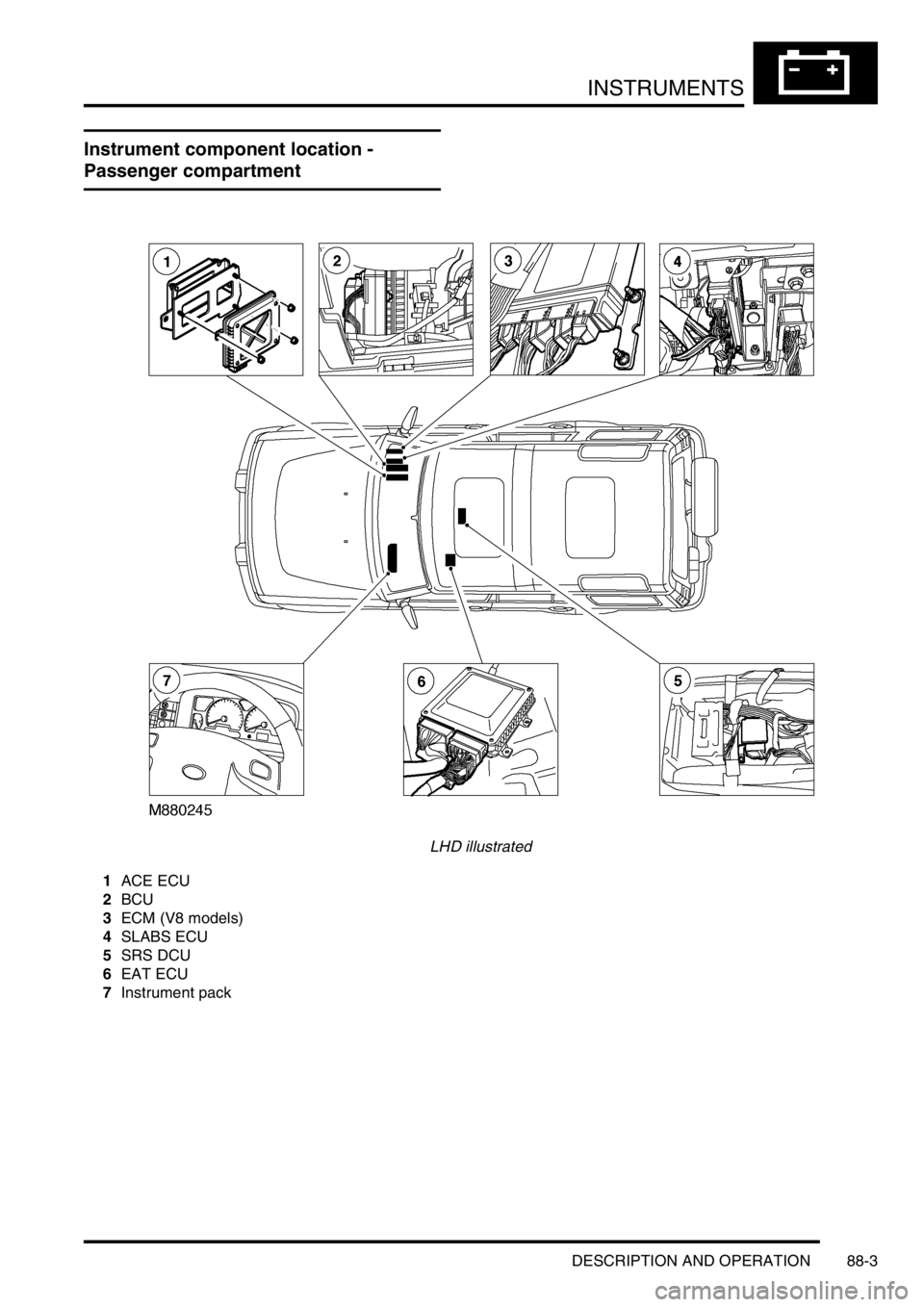
Instrument component location -
Passenger compartment
LHD illustrated
1ACE ECU
2BCU
3ECM (V8 models)
4SLABS ECU
5SRS DCU
6EAT ECU
7Instrument pack
Page 1631 of 1672

INSTRUMENTS
88-4 DESCRIPTION AND OPERATION
Instrument block diagram
1Instrument pack
2ECM
3Brake fluid level switch
4Parking brake switch
5Oil pressure switch
6Alternator
7Fuel tank sender unit
8Water in fuel filter sensor
9Transmission temperature sensor
10Differential lock switch - vehicles up to 03
model year or Differential lock switches -
vehicles from 03 model year11Audible warning speaker
12SRS DCU
13SLABS ECU
14BCU
15ACE ECU
16EAT ECU
17Diagnostic connector
18Serial communications link
Page 1635 of 1672
INSTRUMENTS
88-8 DESCRIPTION AND OPERATION
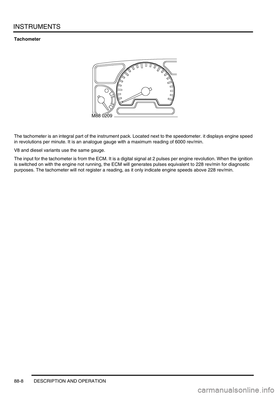
Tachometer
The tachometer is an integral part of the instrument pack. Located next to the speedometer. it displays engine speed
in revolutions per minute. It is an analogue gauge with a maximum reading of 6000 rev/min.
V8 and diesel variants use the same gauge.
The input for the tachometer is from the ECM. It is a digital signal at 2 pulses per engine revolution. When the ignition
is switched on with the engine not running, the ECM will generates pulses equivalent to 228 rev/min for diagnostic
purposes. The tachometer will not register a reading, as it only indicate engine speeds above 228 rev/min.
Page 1636 of 1672
INSTRUMENTS
DESCRIPTION AND OPERATION 88-9
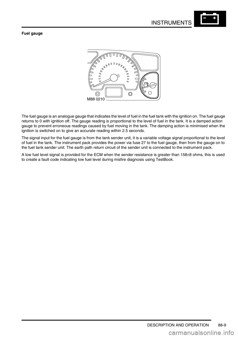
Fuel gauge
The fuel gauge is an analogue gauge that indicates the level of fuel in the fuel tank with the ignition on. The fuel gauge
returns to 0 with ignition off. The gauge reading is proportional to the level of fuel in the tank. It is a damped action
gauge to prevent erroneous readings caused by fuel moving in the tank. The damping action is minimised when the
ignition is switched on to give an accurate reading within 2.5 seconds.
The signal input for the fuel gauge is from the tank sender unit, it is a variable voltage signal proportional to the level
of fuel in the tank. The instrument pack provides the power via fuse 27 to the fuel gauge, then from the gauge on to
the fuel tank sender unit. The earth path return circuit of the sender unit is connected to the instrument pack.
A low fuel level signal is provided for the ECM when the sender resistance is greater than 158
±8 ohms, this is used
to create a fault code indicating low fuel level during misfire diagnosis using TestBook.
Page 1638 of 1672

INSTRUMENTS
DESCRIPTION AND OPERATION 88-11
Engine coolant temperature gauge
The engine coolant temperature gauge is an analogue gauge with three sections: cold temperature; normal operating
temperature; high temperature. Under normal engine operating temperatures the engine coolant temperature gauge
will display in the centre of the gauge. When the engine is cold e.g. from first start-up, the coolant temperature gauge
will display in the cold band. When the engine is over heating the temperature gauge will display in the high
temperature band. If the engine coolant temperature gauge receives no input or the input is out of range the
temperature gauge will read cold and the high coolant temperature warning lamp will be illuminated.
The input signal is a PWM signal from the engine coolant temperature sensor via the ECM. The power input for the
high coolant temperature warning lamp is supplied by the instrument pack via fuse 27. The ECM controls the earth
path to illuminate the high coolant temperature warning lamp.
Page 1639 of 1672

INSTRUMENTS
88-12 DESCRIPTION AND OPERATION
Malfunction Indicator Lamp (MIL)/ SERVICE ENGINE SOON warning lamp
The MIL/service engine soon warning lamp within the instrument pack utilises an amber LED and a clear legend. If
an emission related fault is detected by the engine management system or, on automatic gearbox models, the EAT
ECU, the ECM will illuminate the LED providing the driver with a visible warning.
The warning lamp will illuminate whenever the vehicle is driven until the fault is repaired, and the ECM fault code
memory is cleared using TestBook.
When the ignition is switch on the ECM carries out a self-test function of the lamp. The lamp will illuminate for 3
seconds then extinguish if no faults exist. If a fault is present the lamp will be extinguished for 1 second before
illuminating again to indicate a fault exists.
There are two configurations of the legend for the warning lamp:
lNAS and Canada = SERVICE ENGINE SOON text.
lAll other markets = MIL SAE J1930 symbol.
The power input for the LED is supplied by the instrument pack via fuse 27. The ECM provides a voltage to the
instrument pack Central Processing Unit (CPU) to control the warning lamp:
l< 1.8 volts = warning lamp on.
l> 7.7 volts = warning lamp off.
Page 1641 of 1672
INSTRUMENTS
88-14 DESCRIPTION AND OPERATION
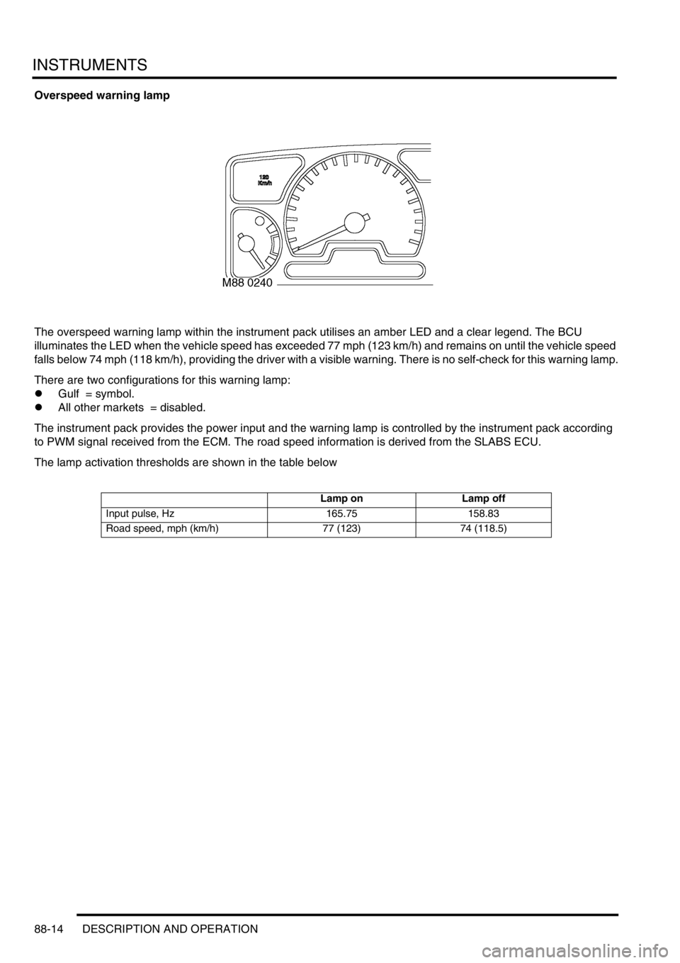
Overspeed warning lamp
The overspeed warning lamp within the instrument pack utilises an amber LED and a clear legend. The BCU
illuminates the LED when the vehicle speed has exceeded 77 mph (123 km/h) and remains on until the vehicle speed
falls below 74 mph (118 km/h), providing the driver with a visible warning. There is no self-check for this warning lamp.
There are two configurations for this warning lamp:
lGulf = symbol.
lAll other markets = disabled.
The instrument pack provides the power input and the warning lamp is controlled by the instrument pack according
to PWM signal received from the ECM. The road speed information is derived from the SLABS ECU.
The lamp activation thresholds are shown in the table below
Lamp on Lamp off
Input pulse, Hz 165.75 158.83
Road speed, mph (km/h) 77 (123) 74 (118.5)
Page 1646 of 1672

INSTRUMENTS
DESCRIPTION AND OPERATION 88-19
High engine coolant temperature warning lamp
The high engine coolant temperature warning lamp within the instrument pack utilises a red LED and a clear legend.
The ECM illuminates the LED when it detects the engine coolant has exceeded a temperature of 121
°C (250 °F) and
switches it off when the coolant temperature drops below 118
°C (244 °F). The ECM also illuminates the high engine
coolant temperature warning lamp when it detects the PWM duty cycle to the temperature gauge is out of range. If it
is greater than 94% duty cycle when the engine is hot, or less than 8% duty cycle when the engine is cold, the engine
coolant temperature gauge pointer will indicate cold, thus alerting the driver with an additional visible warning.
When the ignition is switched on, the ECM illuminates the LED to provide a self-check, providing there is no fault it
will remain illuminated for 3 seconds or until the ignition is switched off.
The response of the engine high temperature warning lamp varies according to engine type and market, there are
three conditions:
lV8 - Gulf.
lV8 - all markets except Gulf.
lDiesel - all markets.
The vehicle configuration determines which condition is set.
The PWM duty cycle thresholds for illuminating and extinguishing the warning lamp are given in the table below.
The power input for the LED is supplied by the instrument pack via fuse 27. The ECM controls the earth path to
illuminate the warning lamp.
Market Lamp on Lamp off
V8 - Gulf 79.8 ± 2% 77.8 ± 2%
V8 - all markets except Gulf 77.8 ± 2% 75.7 ± 2%
Diesel - all markets 78.8 ± 2% 76.8 ± 2%
Page 1647 of 1672
INSTRUMENTS
88-20 DESCRIPTION AND OPERATION
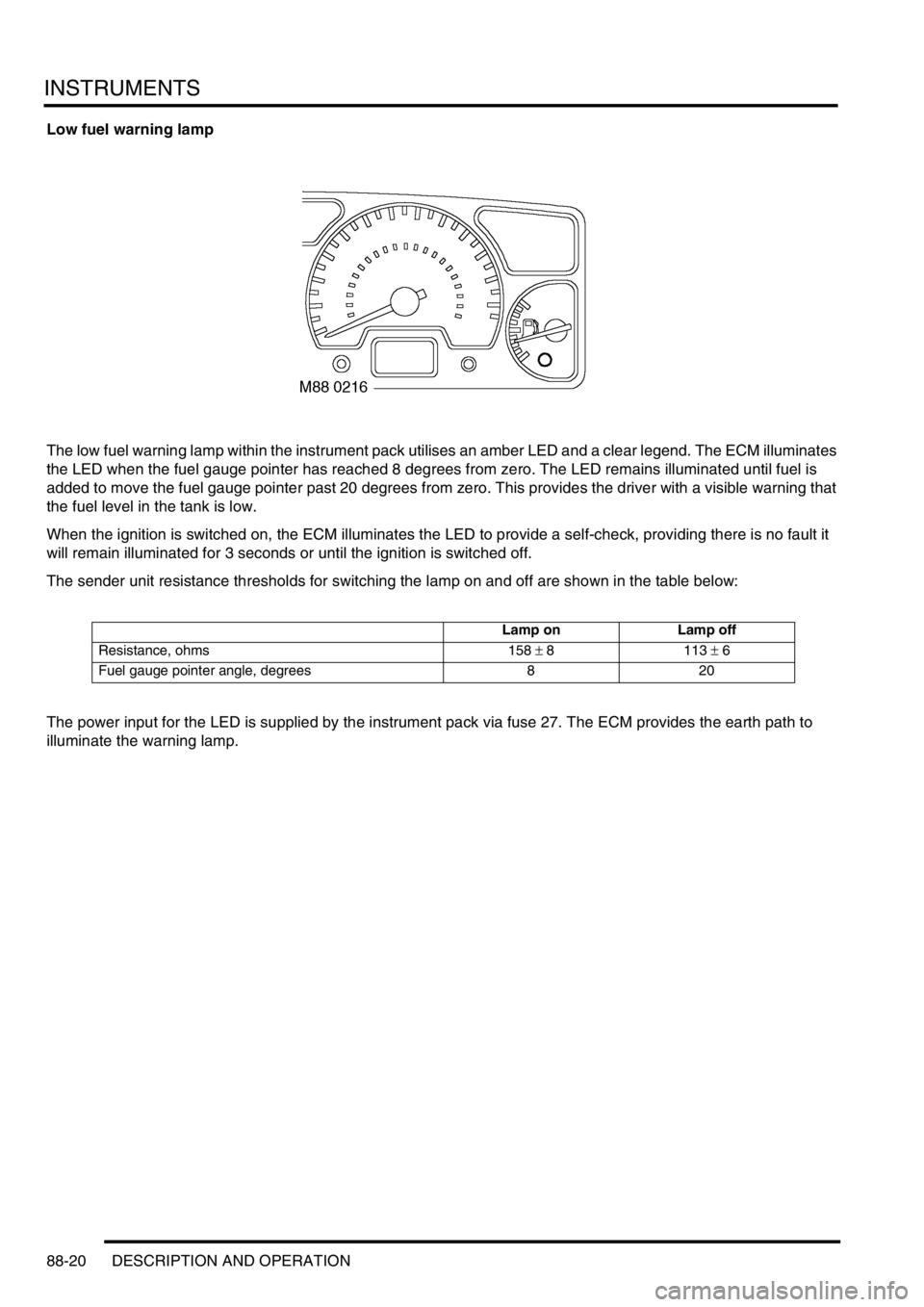
Low fuel warning lamp
The low fuel warning lamp within the instrument pack utilises an amber LED and a clear legend. The ECM illuminates
the LED when the fuel gauge pointer has reached 8 degrees from zero. The LED remains illuminated until fuel is
added to move the fuel gauge pointer past 20 degrees from zero. This provides the driver with a visible warning that
the fuel level in the tank is low.
When the ignition is switched on, the ECM illuminates the LED to provide a self-check, providing there is no fault it
will remain illuminated for 3 seconds or until the ignition is switched off.
The sender unit resistance thresholds for switching the lamp on and off are shown in the table below:
The power input for the LED is supplied by the instrument pack via fuse 27. The ECM provides the earth path to
illuminate the warning lamp.
Lamp on Lamp off
Resistance, ohms 158 ± 8 113 ± 6
Fuel gauge pointer angle, degrees 8 20