gearbox LAND ROVER DISCOVERY 2002 Workshop Manual
[x] Cancel search | Manufacturer: LAND ROVER, Model Year: 2002, Model line: DISCOVERY, Model: LAND ROVER DISCOVERY 2002Pages: 1672, PDF Size: 46.1 MB
Page 800 of 1672

AUTOMATIC GEARBOX - ZF4HP22 - 24
DESCRIPTION AND OPERATION 44-3
1Transmission high/low switch
2Mode switch
3Gear position switch connector
4Solenoid valve/speed sensor connector
5Electronic automatic transmission ECU
6Engine control module
7Diagnostic socket
8Instrument pack
9Transmission fluid temperature sensor
10Body control unit
11Battery power supply
12Ignition power supply
Page 801 of 1672

AUTOMATIC GEARBOX - ZF4HP22 - 24
44-4 DESCRIPTION AND OPERATION
Description
General
The automatic gearbox is a four speed unit with electronic control of gear selection, shift quality and torque converter
lock-up. Selections on the selector lever assembly are transmitted to the gearbox by a selector cable. A gear position
switch on the gearbox transmits the gear selection to an Electronic Automatic Transmission (EAT) ECU, which
outputs the appropriate control signals to an electro-hydraulic valve block in the gearbox. A mode switch enables the
driver to change the control mode of the EAT ECU. The EAT ECU operates warning lamps in the instrument pack to
indicate the control mode and system status.
The gearbox features a pressure lubrication system and is cooled by pumping the lubricant through an oil cooler.
On NAS market vehicles from 03 model year, the ZF 4HP24 transmission unit is introduced for use with the 4.6 litre
V8 engine. This transmission is required to accomodate the increased power output of the larger engine. The ZF
4HP22 transmission remains in use on vehicles with Td5 and 4.0 litre V8 engines.
Both transmission units are of similar construction, with the ZF 4HP24 unit being 15 mm longer than the 4HP22 unit
to accomodate a larger fluid pump. The operation of both transmission units is the same.
Selector lever assembly
Page 802 of 1672

AUTOMATIC GEARBOX - ZF4HP22 - 24
DESCRIPTION AND OPERATION 44-5
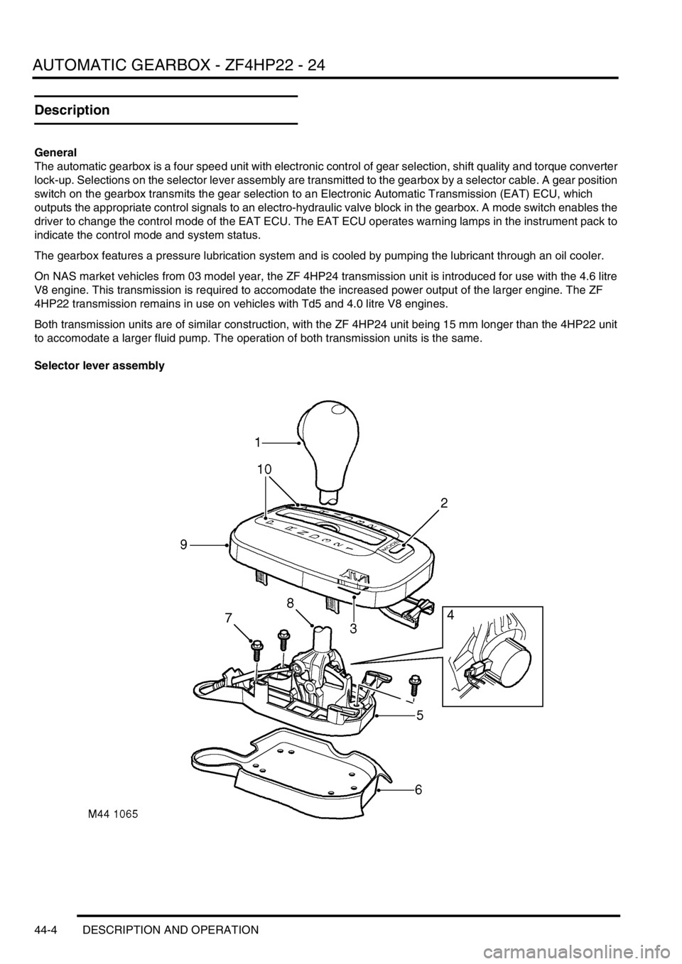
1Release button
2Mode switch
3Electrical connector
4Interlock solenoid (where fitted)
5Base6Gasket
7Securing bolt
8Lever
9Cover
10Position indicators
The selector lever assembly consists of a lever and a cover attached to a base. The base is located on a gasket and
secured to the transmission tunnel. The lever is hinged to the base. A latch in the lever engages with detents in the
base to provide the lever positions P, R, N, D, 3, 2, 1. The latch is disengaged by pressing a release button on the
lever knob. Except for lever movement between positions D and 3, the button must be pressed before the lever can
be moved. In some markets, vehicles incorporate an interlock solenoid at the bottom of the lever, which prevents the
lever being moved from P unless the ignition switch is in position II and the foot brake is applied. If the battery
becomes flat, the interlock system will prevent selector lever movement and removal of the ignition key.
The cover incorporates lever position indicators and the mode switch. The lever position indicators illuminate to show
the position of the selector lever. Illumination is controlled by the Body Control Unit (BCU). The mode switch is a non-
latching hinged switch that, when pressed, connects an earth to the EAT ECU to request a change of mode.
An electrical connector at the rear of the cover connects the selector lever assembly to the vehicle wiring.
Selector cable
The selector cable is a Bowden type cable that connects the selector lever assembly to a selector lever on the
gearbox. 'C' clips secure the ends of the outer cable to brackets on the selector lever assembly and the selector lever.
The inner cable is adjustable at the connection of the inner cable with the gearbox selector lever.
Page 803 of 1672

AUTOMATIC GEARBOX - ZF4HP22 - 24
44-6 DESCRIPTION AND OPERATION
Gearbox
Diesel gearbox shown, V8 gearbox similar
1Torque converter
2Torque converter housing
3Fluid pump
4Breather tube
5Intermediate plate
6Gearbox housing
7Rear extension housing
8Electrical connector
9Gear position switch
10Selector lever
11Mounting bracket12Heat shield
13Rubber mounting
14Gasket
15Sump
16'O' ring seal
17Drain plug
18'O' ring seal
19Filler/level plug
20Bolt
21Clamp
Page 804 of 1672

AUTOMATIC GEARBOX - ZF4HP22 - 24
DESCRIPTION AND OPERATION 44-7
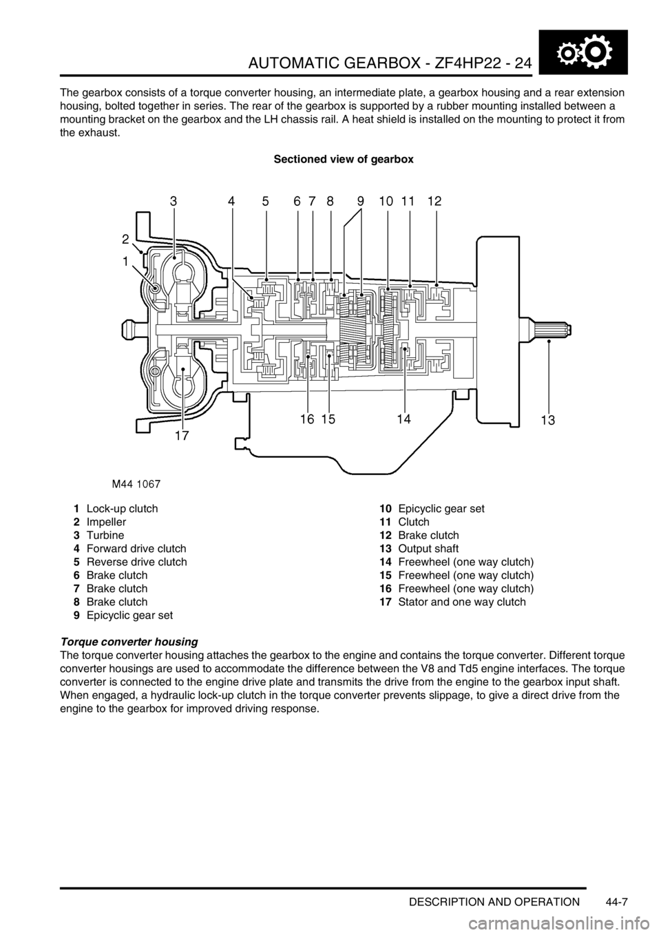
The gearbox consists of a torque converter housing, an intermediate plate, a gearbox housing and a rear extension
housing, bolted together in series. The rear of the gearbox is supported by a rubber mounting installed between a
mounting bracket on the gearbox and the LH chassis rail. A heat shield is installed on the mounting to protect it from
the exhaust.
Sectioned view of gearbox
1Lock-up clutch
2Impeller
3Turbine
4Forward drive clutch
5Reverse drive clutch
6Brake clutch
7Brake clutch
8Brake clutch
9Epicyclic gear set10Epicyclic gear set
11Clutch
12Brake clutch
13Output shaft
14Freewheel (one way clutch)
15Freewheel (one way clutch)
16Freewheel (one way clutch)
17Stator and one way clutch
Torque converter housing
The torque converter housing attaches the gearbox to the engine and contains the torque converter. Different torque
converter housings are used to accommodate the difference between the V8 and Td5 engine interfaces. The torque
converter is connected to the engine drive plate and transmits the drive from the engine to the gearbox input shaft.
When engaged, a hydraulic lock-up clutch in the torque converter prevents slippage, to give a direct drive from the
engine to the gearbox for improved driving response.
Page 805 of 1672

AUTOMATIC GEARBOX - ZF4HP22 - 24
44-8 DESCRIPTION AND OPERATION
Intermediate plate
The intermediate plate supports the gearbox input shaft and provides the interface between the transmission fluid
pump and the lubrication circuit. The pump attaches to the front of the intermediate plate and is driven by the impeller
in the torque converter. The pump pressurises transmission fluid drawn from the sump on the gearbox housing. The
pressurised fluid then circulates through the torque converter and gearbox housing components for cooling,
lubrication and gear shift purposes. Ports around the outer periphery of the intermediate plate provide the inlet and
outlet connections to the fluid cooler and a pressure take-off point for servicing.
Gearbox housing
The gearbox housing contains two epicyclic gear sets on input and output shafts. Hydraulic brake clutches on the
shafts, control which elements of the gear sets are engaged, and their direction of rotation, to produce the P and N
selections, four forward gear ratios and one reverse gear ratio.
Gear ratios
Gear Ratio
1st 2.480 : 1
2nd 1.480 : 1
3rd 1.000 : 1
4th 0.728 : 1
Reverse 2.086 : 1
Page 806 of 1672

AUTOMATIC GEARBOX - ZF4HP22 - 24
DESCRIPTION AND OPERATION 44-9
Valve block
1Valve block
2Pressure regulating solenoid valve (MV 4)
3Shift control solenoid valve (MV 2)
4Shift control solenoid valve (MV 1)
5Lock-up solenoid valve (MV 3)
6Output shaft speed sensor
7Bolt
8Sensor retaining clip9Manual valve
10'O' ring
11Filter
12'O' ring
13Suction pipe
14Bolt
15Bolt
16Washer
Page 807 of 1672

AUTOMATIC GEARBOX - ZF4HP22 - 24
44-10 DESCRIPTION AND OPERATION
The lock-up and brake clutches are operated by pressurised transmission fluid from the valve block in the sump. A
manual valve and four solenoid valves, also known as Motorised Valves (MV), control the supply of pressurised
transmission fluid from the valve block:
lThe manual valve controls the supply in P, R, N and D.
lSolenoid valves MV 1 and MV 2 control the supplies that operate the brake clutches for shift control.
lSolenoid valve MV 3 controls the supply that operates the lock-up clutch.
lSolenoid valve MV 4 modulates the pressure of the supplies to the brake clutches, to control shift quality.
Operation of the manual valve is controlled by the selector lever assembly. In the gearbox, a selector shaft engages
with the manual valve. The selector shaft is connected to the selector lever assembly via the selector cable and a
selector lever on the left side of the gearbox. The selector shaft also operates a mechanism that locks the output shaft
when P is selected.
Operation of the solenoid valves is controlled by the EAT ECU.
An output shaft speed sensor in the gearbox housing outputs a signal to the EAT ECU. The EAT ECU compares
output shaft speed with engine speed to determine the engaged gear, and output shaft speed with vehicle speed to
confirm the range selected on the transfer box.
A bayonet lock electrical connector in the gearbox casing, to the rear of the selector lever, connects the solenoid
valves and the output shaft speed sensor to the vehicle wiring.
A pressed steel sump encloses the valve block and collects transmission fluid draining from the gearbox housing. A
suction pipe and filter on the underside of the valve block connect to the inlet side of the fluid pump. A magnet is
installed in the sump to collect any magnetic particles that may be present. A level plug and a drain plug are installed
in the sump for servicing.
Rear extension housing
The rear extension housing provides the interface between the gearbox housing and the transfer box. A splined
extension shaft, secured to the gearbox output shaft by a bolt, transmits the drive from the gearbox to the transfer
box. A seal in the rear of the housing prevents leakage past the extension shaft. A breather pipe, attached to the left
side of the rear extension housing, ventilates the interior of the gearbox and rear extension housings to atmosphere.
The open end of the breather pipe is located in the engine compartment at the right front corner of the engine sump
on gearboxes fitted to early vehicles and is clipped to the top of the gearbox on later vehicles.
Gearbox power flows
The following Figures show the power flow through the gearbox for each forward gear when D is selected, and for
reverse. The key to the Item numbers on the Figures, and in parenthesis in the accompanying text, can be found on
the 'Sectioned view of gearbox' Figure, above.
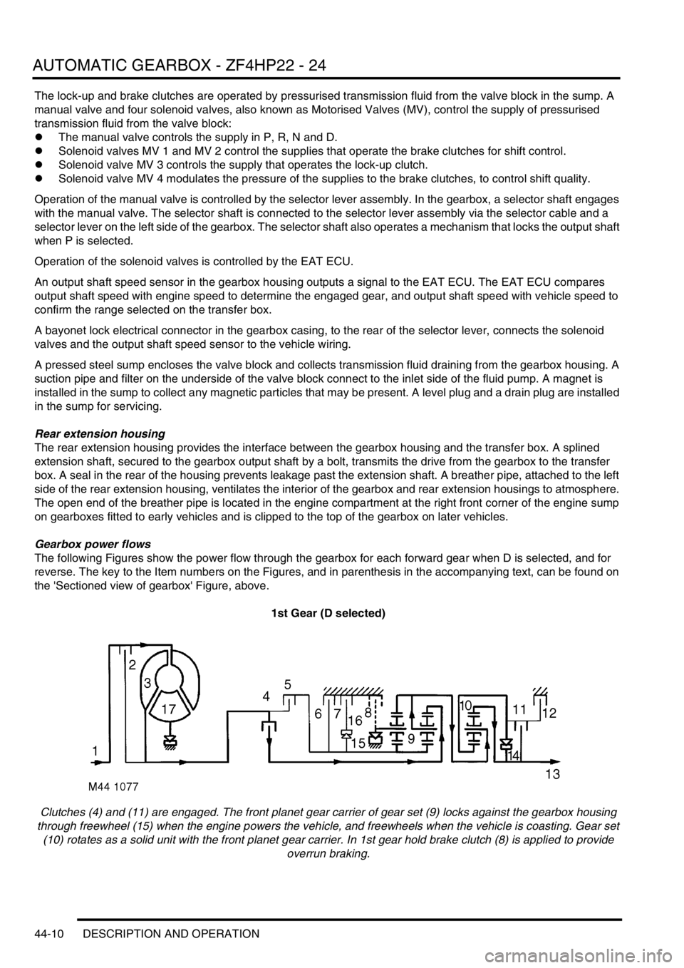
1st Gear (D selected)
Clutches (4) and (11) are engaged. The front planet gear carrier of gear set (9) locks against the gearbox housing
through freewheel (15) when the engine powers the vehicle, and freewheels when the vehicle is coasting. Gear set
(10) rotates as a solid unit with the front planet gear carrier. In 1st gear hold brake clutch (8) is applied to provide
overrun braking.
Page 808 of 1672

AUTOMATIC GEARBOX - ZF4HP22 - 24
DESCRIPTION AND OPERATION 44-11
2nd Gear (D selected)
Clutches (4), (6), (7) and (11) are engaged. Freewheel (15) overruns. The hollow shaft with the sun wheel of gear set
(9) is locked. Gear set (10) also rotates as a solid unit.
3rd Gear (D selected)
Clutches (4), (5), (7) and (11) are engaged. Freewheels (15) and (16) are overrun. Gear sets (9) and (10) rotate as a
solid unit.
4th Gear (D selected)
Clutches (4), (5), (7) and (12) are engaged. Freewheels (14), (15) and (16) are overrun. Gear set (9) rotates as a solid
unit. The hollow shaft with the sun wheel of gear set (10) is locked.
Page 809 of 1672

AUTOMATIC GEARBOX - ZF4HP22 - 24
44-12 DESCRIPTION AND OPERATION
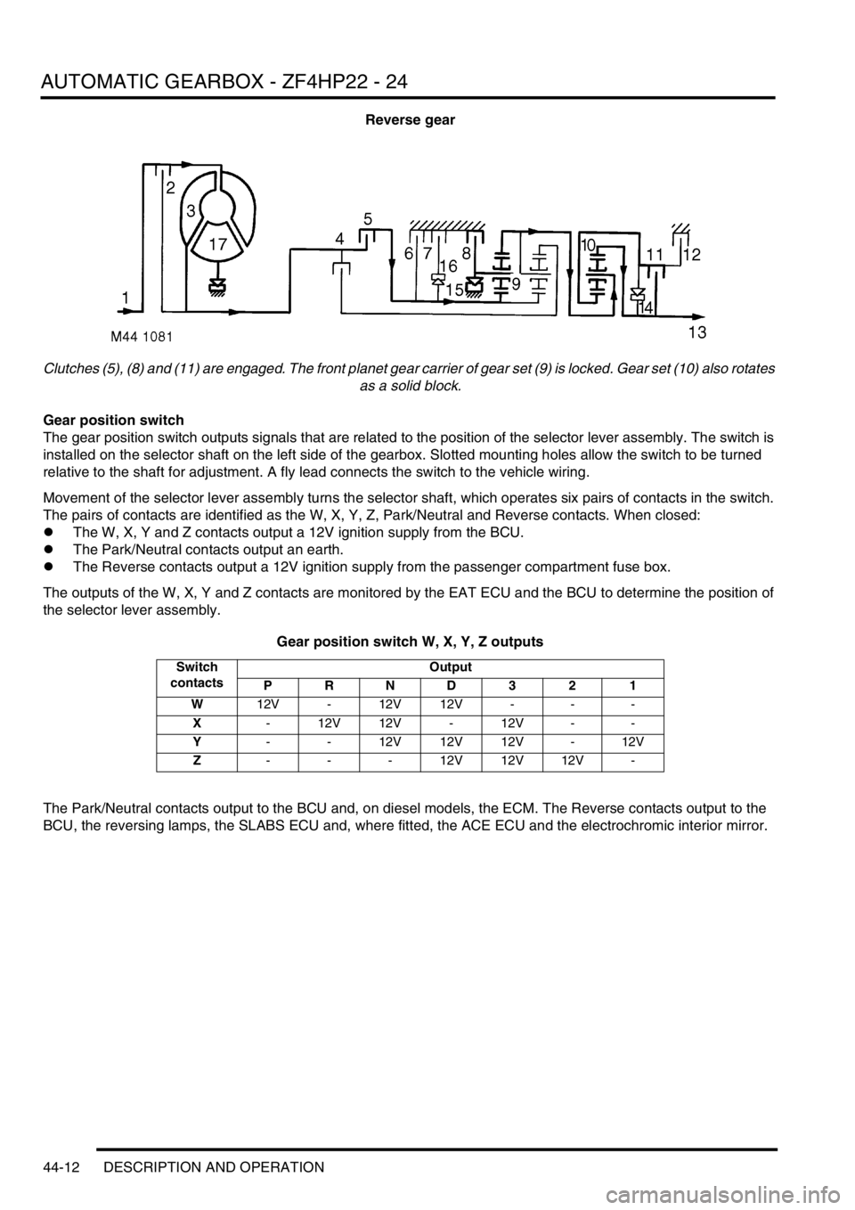
Reverse gear
Clutches (5), (8) and (11) are engaged. The front planet gear carrier of gear set (9) is locked. Gear set (10) also rotates
as a solid block.
Gear position switch
The gear position switch outputs signals that are related to the position of the selector lever assembly. The switch is
installed on the selector shaft on the left side of the gearbox. Slotted mounting holes allow the switch to be turned
relative to the shaft for adjustment. A fly lead connects the switch to the vehicle wiring.
Movement of the selector lever assembly turns the selector shaft, which operates six pairs of contacts in the switch.
The pairs of contacts are identified as the W, X, Y, Z, Park/Neutral and Reverse contacts. When closed:
lThe W, X, Y and Z contacts output a 12V ignition supply from the BCU.
lThe Park/Neutral contacts output an earth.
lThe Reverse contacts output a 12V ignition supply from the passenger compartment fuse box.
The outputs of the W, X, Y and Z contacts are monitored by the EAT ECU and the BCU to determine the position of
the selector lever assembly.
Gear position switch W, X, Y, Z outputs
The Park/Neutral contacts output to the BCU and, on diesel models, the ECM. The Reverse contacts output to the
BCU, the reversing lamps, the SLABS ECU and, where fitted, the ACE ECU and the electrochromic interior mirror.
Switch
contactsOutput
PRND 3 2 1
W12V - 12V 12V - - -
X- 12V 12V - 12V - -
Y- - 12V 12V 12V - 12V
Z- - - 12V 12V 12V -