cooling system - td5 LAND ROVER DISCOVERY 2002 Owner's Guide
[x] Cancel search | Manufacturer: LAND ROVER, Model Year: 2002, Model line: DISCOVERY, Model: LAND ROVER DISCOVERY 2002Pages: 1672, PDF Size: 46.1 MB
Page 436 of 1672

ENGINE MANAGEMENT SYSTEM - TD5
DESCRIPTION AND OPERATION 18-1-43
Air Conditioning (A/C)
The ECM controls operation of the A/C compressor and the engine's electric cooling fan in response to requests from
the Automatic Temperature Control (ATC) ECU.
A/C request
When the ATC ECU supplies the ECM with an A/C request, the ECM energises the compressor clutch relay. The
compressor clutch relay is located in the engine compartment fuse box. It is a four pin normally open relay. This means
that the relay must be energised to drive the compressor clutch. During periods of high driver demand such as hard
acceleration or maximum rev/min the ECM will disable the compressor clutch for a short time. This is to reduce the
load on the engine.
The operation of the A/C request is via a switch being connected to earth. Voltage is supplied via pin 9 of connector
C0658 of the ECM, at the point at which the switch is pressed the connection to the earth path is made and the
compressor clutch is engaged.
The ECM provides the earth for the relay windings to allow the compressor clutch relay contacts to close and the
compressor clutch drive to receive battery voltage. The ECM uses a transistor as a switch to generate an open circuit
in the earth path of the relay windings. When the ECM closes down the earth path, the return spring in the relay will
pull the contacts apart to shut down the compressor clutch drive. Fuse 6, located in the engine compartment fuse box,
provides voltage to the compressor clutch relay switching contacts. The relay windings are supplied with battery
voltage from the main relay, also located in the engine compartment fuse box. The earth path for the relay windings
is via pin 29 of the ECM connector C0658. When the relay is energised the output from the switching contacts is
directly to the compressor clutch.
Cooling fan request
The A/C fan request is an input to the ECM from the ATC ECU to request that the engine's electric cooling fan is
activated to provide additional cooling for the A/C condenser.
The cooling fan relay is located in the engine compartment fuse box and is also controlled by the ECM. It is a four pin
normally open relay. This means that the relay must be energised to drive the cooling fan. The cooling fan is used
especially when the engine is operating at excessively high temperatures. It is also used as a part of the ECM backup
strategy if the ECT sensor fails.
The operation of the cooling fan request is via a switch being connected to earth. Voltage is supplied via pin 23 of
connector C0658 of the ECM, at the point at when the switch is pressed the connection to the earth path is made and
the cooling fan is engaged.
The ECM provides the earth for the cooling fan relay windings to allow the relay contacts to close and the cooling fan
motor to receive battery voltage. The ECM uses a transistor as a switch to generate an open circuit in the earth path
of the relay windings. When the ECM closes down the earth path, the return spring in the relay will pull the contacts
apart to shut down the cooling fan motor drive. Input to the A/C cooling fan relay switching contacts is via fuse 4
located in the engine compartment fuse box. The relay windings are supplied with battery voltage from the main relay,
also located in the engine compartment fuse box. The earth path for the relay windings is via pin 4 of the ECM
connector C0658. When the relay is energised the output from the switching contacts is directly to the cooling fan
motor.
Page 440 of 1672

ENGINE MANAGEMENT SYSTEM - TD5
REPAIRS 18-1-47
REPAIRS
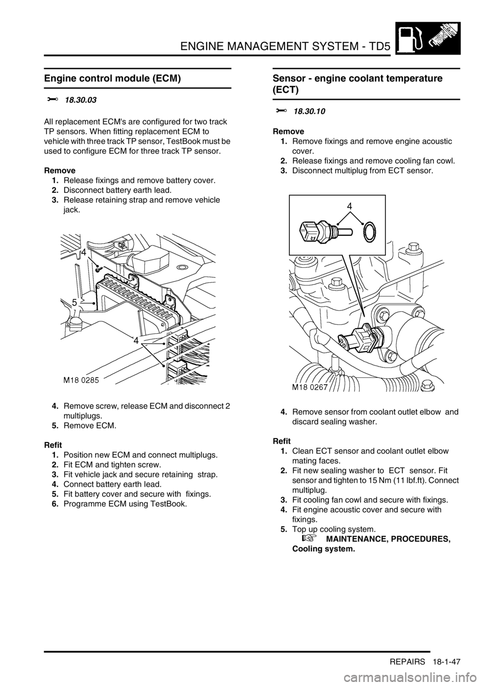
Engine control module (ECM)
$% 18.30.03
All replacement ECM's are configured for two track
TP sensors. When fitting replacement ECM to
vehicle with three track TP sensor, TestBook must be
used to configure ECM for three track TP sensor.
Remove
1.Release fixings and remove battery cover.
2.Disconnect battery earth lead.
3.Release retaining strap and remove vehicle
jack.
4.Remove screw, release ECM and disconnect 2
multiplugs.
5.Remove ECM.
Refit
1.Position new ECM and connect multiplugs.
2.Fit ECM and tighten screw.
3.Fit vehicle jack and secure retaining strap.
4.Connect battery earth lead.
5.Fit battery cover and secure with fixings.
6.Programme ECM using TestBook.
Sensor - engine coolant temperature
(ECT)
$% 18.30.10
Remove
1.Remove fixings and remove engine acoustic
cover.
2.Release fixings and remove cooling fan cowl.
3.Disconnect multiplug from ECT sensor.
4.Remove sensor from coolant outlet elbow and
discard sealing washer.
Refit
1.Clean ECT sensor and coolant outlet elbow
mating faces.
2.Fit new sealing washer to ECT sensor. Fit
sensor and tighten to 15 Nm (11 lbf.ft). Connect
multiplug.
3.Fit cooling fan cowl and secure with fixings.
4.Fit engine acoustic cover and secure with
fixings.
5.Top up cooling system.
+ MAINTENANCE, PROCEDURES,
Cooling system.
Page 446 of 1672

ENGINE MANAGEMENT SYSTEM - TD5
REPAIRS 18-1-53
Element - fuel filter
$% 19.25.07
Remove
1.Release turnbuckles and remove battery cover.
2.Disconnect battery earth lead.
3.Raise rear of vehicle.
WARNING: Do not work on or under a
vehicle supported only by a jack. Always
support the vehicle on safety stands.
4.Clean area around fuel filter.
5.Disconnect multiplug from filter element.
6.Remove fuel filter element.
Refit
1.Clean fuel filter and mating face.
2.Fit new fuel filter element and connect
multiplug.
3.Remove stand(s) and lower vehicle.
4.Connect battery earth lead.
5.Fit battery cover and secure the fixings.
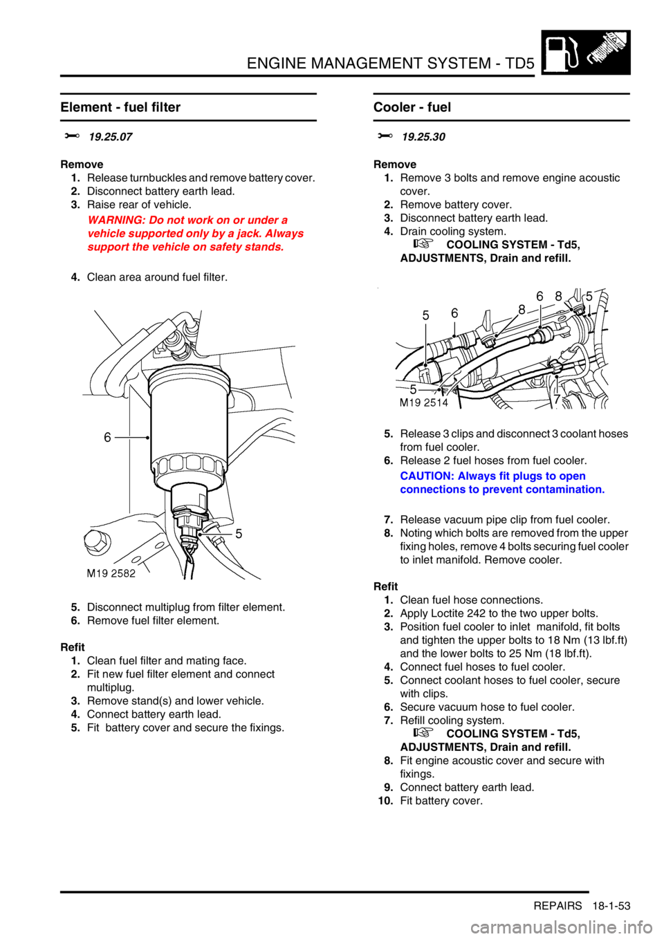
Cooler - fuel
$% 19.25.30
Remove
1.Remove 3 bolts and remove engine acoustic
cover.
2.Remove battery cover.
3.Disconnect battery earth lead.
4.Drain cooling system.
+ COOLING SYSTEM - Td5,
ADJUSTMENTS, Drain and refill.
5.Release 3 clips and disconnect 3 coolant hoses
from fuel cooler.
6.Release 2 fuel hoses from fuel cooler.
CAUTION: Always fit plugs to open
connections to prevent contamination.
7.Release vacuum pipe clip from fuel cooler.
8.Noting which bolts are removed from the upper
fixing holes, remove 4 bolts securing fuel cooler
to inlet manifold. Remove cooler.
Refit
1.Clean fuel hose connections.
2.Apply Loctite 242 to the two upper bolts.
3.Position fuel cooler to inlet manifold, fit bolts
and tighten the upper bolts to 18 Nm (13 lbf.ft)
and the lower bolts to 25 Nm (18 lbf.ft).
4.Connect fuel hoses to fuel cooler.
5.Connect coolant hoses to fuel cooler, secure
with clips.
6.Secure vacuum hose to fuel cooler.
7.Refill cooling system.
+ COOLING SYSTEM - Td5,
ADJUSTMENTS, Drain and refill.
8.Fit engine acoustic cover and secure with
fixings.
9.Connect battery earth lead.
10.Fit battery cover.
Page 448 of 1672

ENGINE MANAGEMENT SYSTEM - TD5
REPAIRS 18-1-55
Turbocharger
$% 19.42.01
Remove
1.Remove 3 bolts and remove engine acoustic
cover.
2.Release fixings and remove battery cover.
3.Disconnect battery earth lead.
4.Remove cooling fan cover.
5.Remove 3 bolts and remove exhaust manifold
heat shield.
6.Release clip and disconnect breather hose
from camshaft cover.
7.Release clip and disconnect vacuum hose from
turbocharger wastegate.
8.Loosen clips and release air intake and outlet
hoses from turbocharger. 9.Remove turbocharger oil feed banjo bolt and
discard sealing washers.
10.Remove 2 bolts and release turbocharger oil
drain pipe and discard gasket.
11.Remove 3 nuts and release exhaust front pipe
from turbocharger and discard gasket.
12.Remove 3 nuts securing turbocharger to
exhaust manifold.
13. Remove turbocharger and discard gasket.
Refit
1.Clean turbocharger and exhaust manifold
mating faces.
2.Using a new gasket, fit turbocharger to exhaust
manifold and tighten nuts to 30 Nm (22 lbf.ft).
3.Using new gasket, align exhaust front pipe and
tighten nuts to 30 Nm (22 lbf.ft).
4.Using new gasket, align turbocharger drain
pipe and tighten bolts to 9 Nm (7 lbf.ft).
5.Fit banjo bolt to oil feed pipe using new sealing
washers and tighten to 25 Nm (18 lbf.ft)..
6.Position air hoses to turbocharger and tighten
clips.
7.Position and secure breather hose to camshaft
cover.
8.Position and secure vacuum hose to
turbocharger wastegate.
9.Position exhaust manifold heat shield and
tighten M6 bolts to 9 Nm (7 lbf.ft) and M8 bolt to
25 Nm (18 lbf.ft).
10.Fit fan cowl and secure fixings.
11.Fit acoustic cover and secure the fixings.
12.Connect battery earth lead.
13.Fit battery cover and secure fixings.
Page 449 of 1672

ENGINE MANAGEMENT SYSTEM - TD5
18-1-56 REPAIRS
Intercooler
$% 19.42.15
Remove
1.Remove cooling fan and coupling.
+ COOLING SYSTEM - Td5, REPAIRS,
Fan - viscous.
2.Remove battery.
3.Remove vehicle jack from battery carrier.
4.Remove screw and release engine control
module (ECM) from battery carrier.
5.Remove 7 bolts and remove battery carrier. 6.Remove 2 screws and remove lower half of fan
cowl.
7.Remove front grille.
+ EXTERIOR FITTINGS, REPAIRS,
Grille - front - up to 03MY.
8.Remove 6 scrivets and remove LH and RH air
deflectors from front panel.
Page 451 of 1672

ENGINE MANAGEMENT SYSTEM - TD5
18-1-58 REPAIRS
3.Fit brackets with rubber mountings to
intercooler and fit and tighten screws securing
brackets to condenser.
4.Fit radiator upper mounting brackets and
tighten bolts.
5.Fit LH horn and secure with nut.
6.Connect inlet and outlet hoses to intercooler
and tighten clips.
7.Fit lower half of fan cowl and secure with
screws.
8.Fit LH and RH air deflectors to front panel and
secure with scrivets.
9.Fit front grille.
10.Fit battery carrier and secure with bolts.
11.Fit ECM and secure with screw.
12.Fit jack to battery carrier.
13.Fit battery.
14.Fit cooling fan and coupling.
+ COOLING SYSTEM - Td5, REPAIRS,
Fan - viscous.
Valve - solenoid boost control
$% 19.42.30
Remove
1.Loosen clip and release air intake hose from
MAF sensor.
2.Release clips and disconnect vacuum hoses
from solenoid valve.
3.Disconnect multiplug from solenoid valve.
4.Remove 2 bolts and remove solenoid valve.
Refit
1.Position solenoid valve and tighten bolts.
2.Connect multiplug to solenoid valve.
3.Connect vacuum hoses and secure with clips.
4.Position air intake hose to MAF sensor and
secure clip.
Page 454 of 1672

ENGINE MANAGEMENT SYSTEM - TD5
REPAIRS 18-1-61
Injectors
$% 19.60.12
Remove
1.Remove cooling fan.
+ COOLING SYSTEM - Td5, REPAIRS,
Fan - viscous.
2.Remove rocker shaft.
+ ENGINE - Td5, REPAIRS, Rocker
shaft assembly.
3.Position container to catch fuel spillage.
4.Disconnect quick release fuel hose connectors
from fuel connector block on cylinder head and
fuel cooler to drain fuel from cylinder head. 5.Disconnect 5 multiplugs from injectors.
6.Remove 5 Torx bolts securing injectors to
cylinder head.
7.Using LRT-12-154/1, remove injectors from
cylinder head. Collect retainers.
8.Using LRT-12-154/4, remove sealing washers
from injectors. Discard sealing washers.
9.Remove and discard 'O' rings from injectors.
10.Rotate engine manually until each cylinder
being worked on is at TDC, and remove excess
fuel from piston bowl using a syringe.
Page 455 of 1672

ENGINE MANAGEMENT SYSTEM - TD5
18-1-62 REPAIRS
Refit
1.Clean injector units and mating faces in
cylinder head.
2.Using LRT-12-154/2, fit a new 'O' ring to each
injector.
3.Using LRT-12-154/3, fit a new sealing washer
to each injector.
4.Fit retainer to injector. Carefully fit injector,
ensuring retainer is located on its dowel, and
tighten Torx bolt to 32 Nm (24 lbf.ft)
5.Connect multiplug to injector.
6.Repeat above operations for remaining
injectors.
7.Connect fuel hoses to connector block and fuel
cooler.
8.Programme new injectors using TestBook.
9.Fit rocker shaft.
+ ENGINE - Td5, REPAIRS, Rocker
shaft assembly.
10.Fit cooling fan.
+ COOLING SYSTEM - Td5, REPAIRS,
Fan - viscous.
Switch - cruise control (on/off)
$% 19.75.30
Remove
1.Carefully remove switch from instrument cowl.
2.Disconnect multiplug and remove switch.
Refit
1.Position new switch and connect multiplug.
2.Carefully push switch into instrument cowl.
Page 584 of 1672

COOLING SYSTEM - TD5
DESCRIPTION AND OPERATION 26-1-1
Deze pagina werd opzettelijk niet gebruikt
Cette page est intentionnellement vierge
Questa pagina è stata lasciata in bianco di proposito Diese Seite ist leer
Esta página foi deixada intencionalmente em branco
Esta página fue dejada en blanco intencionalmente This page is intentionally left blank
COOLING SYSTEM - Td5 DESCRIPTION AND OPERAT ION
Page 585 of 1672

COOLING SYSTEM - TD5
26-1-2 DESCRIPTION AND OPERATION
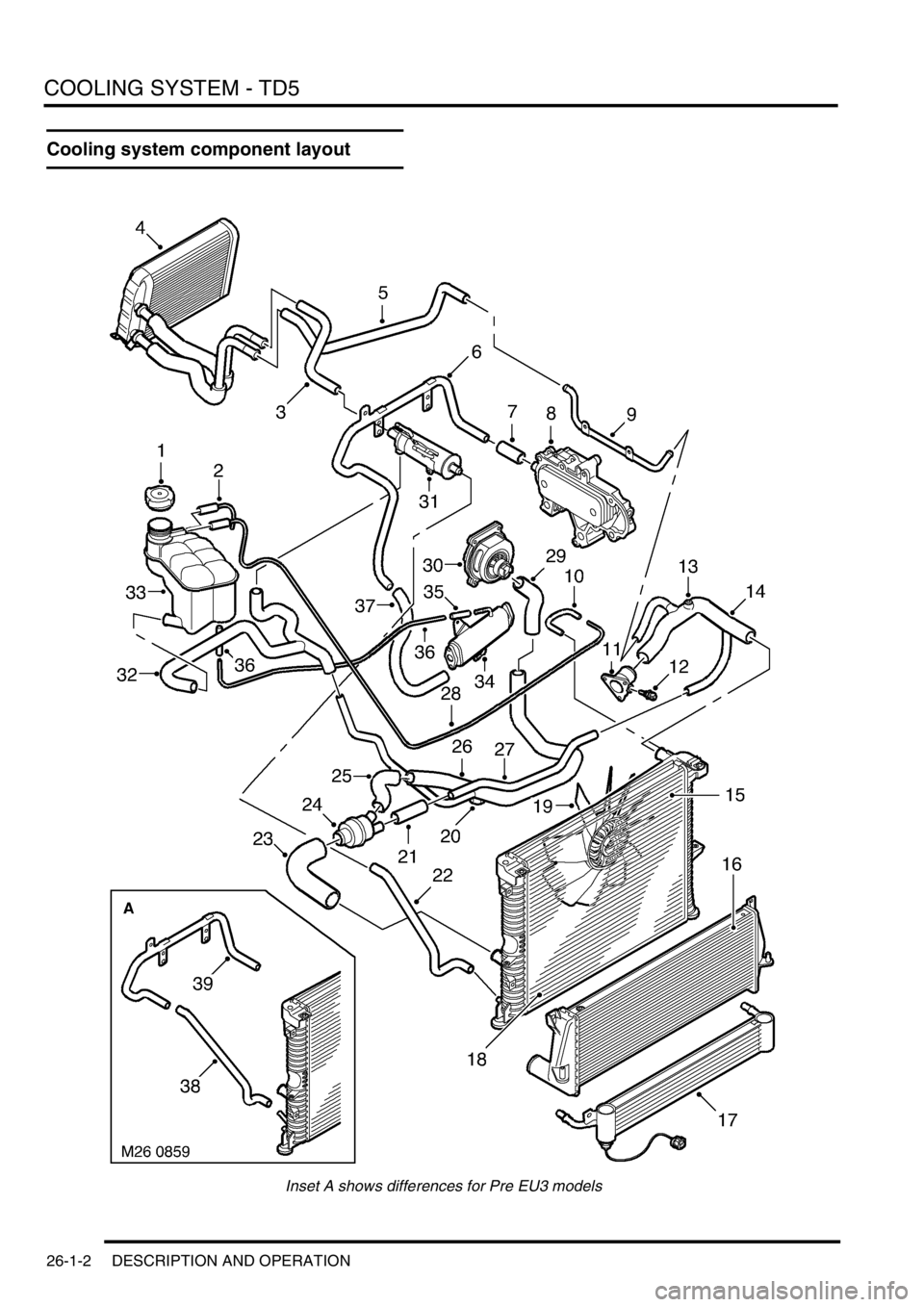
Cooling system component layout
Inset A shows differences for Pre EU3 models