sensor LAND ROVER DISCOVERY 2002 Service Manual
[x] Cancel search | Manufacturer: LAND ROVER, Model Year: 2002, Model line: DISCOVERY, Model: LAND ROVER DISCOVERY 2002Pages: 1672, PDF Size: 46.1 MB
Page 284 of 1672
ENGINE - V8
REPAIRS 12-2-41
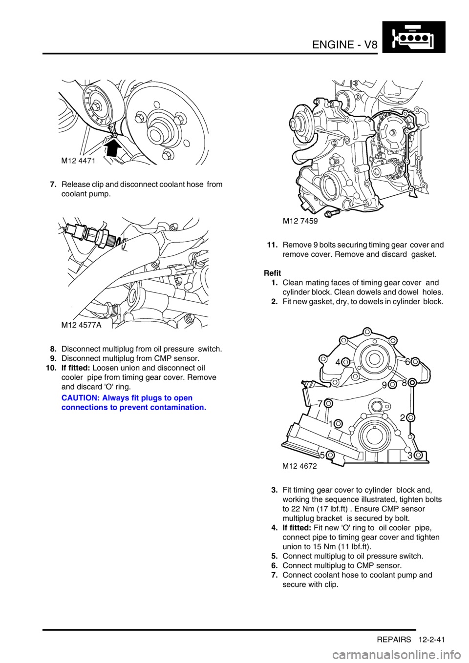
7.Release clip and disconnect coolant hose from
coolant pump.
8.Disconnect multiplug from oil pressure switch.
9.Disconnect multiplug from CMP sensor.
10. If fitted: Loosen union and disconnect oil
cooler pipe from timing gear cover. Remove
and discard 'O' ring.
CAUTION: Always fit plugs to open
connections to prevent contamination.11.Remove 9 bolts securing timing gear cover and
remove cover. Remove and discard gasket.
Refit
1.Clean mating faces of timing gear cover and
cylinder block. Clean dowels and dowel holes.
2.Fit new gasket, dry, to dowels in cylinder block.
3.Fit timing gear cover to cylinder block and,
working the sequence illustrated, tighten bolts
to 22 Nm (17 lbf.ft) . Ensure CMP sensor
multiplug bracket is secured by bolt.
4. If fitted: Fit new 'O' ring to oil cooler pipe,
connect pipe to timing gear cover and tighten
union to 15 Nm (11 lbf.ft).
5.Connect multiplug to oil pressure switch.
6.Connect multiplug to CMP sensor.
7.Connect coolant hose to coolant pump and
secure with clip.
Page 292 of 1672
ENGINE - V8
OVERHAUL 12-2-49
Seal - crankshaft - rear - automatic
models
$% 12.21.20.01
Disassembly
1.Remove CKP sensor.
+ ENGINE MANAGEMENT SYSTEM -
V8, REPAIRS, Sensor - crankshaft position
(CKP).
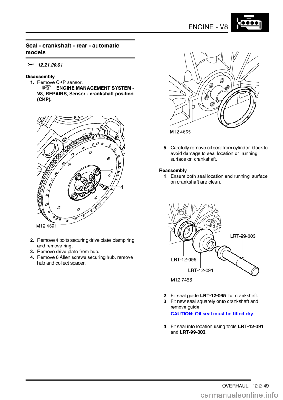
2.Remove 4 bolts securing drive plate clamp ring
and remove ring.
3.Remove drive plate from hub.
4.Remove 6 Allen screws securing hub, remove
hub and collect spacer. 5.Carefully remove oil seal from cylinder block to
avoid damage to seal location or running
surface on crankshaft.
Reassembly
1.Ensure both seal location and running surface
on crankshaft are clean.
2.Fit seal guide LRT-12-095 to crankshaft.
3.Fit new seal squarely onto crankshaft and
remove guide.
CAUTION: Oil seal must be fitted dry.
4.Fit seal into location using tools LRT-12-091
and LRT-99-003.
Page 293 of 1672
ENGINE - V8
12-2-50 OVERHAUL
5.Clean hub and mating face, spacer and clamp
ring.
6.Clean drive plate and ensure free from cracks
and distortion.
7.Fit spacer and hub to crankshaft, tighten Allen
screws to 78 Nm (58 lbf.ft).
8.Fit drive plate and clamp ring, tighten bolts to
45 Nm (35 lbf.ft).
9.Fit CKP sensor.
+ ENGINE MANAGEMENT SYSTEM -
V8, REPAIRS, Sensor - crankshaft position
(CKP).
Seal - crankshaft - rear - manual models
$% 12.21.20.01
Disassembly
1.Restrain flywheel.
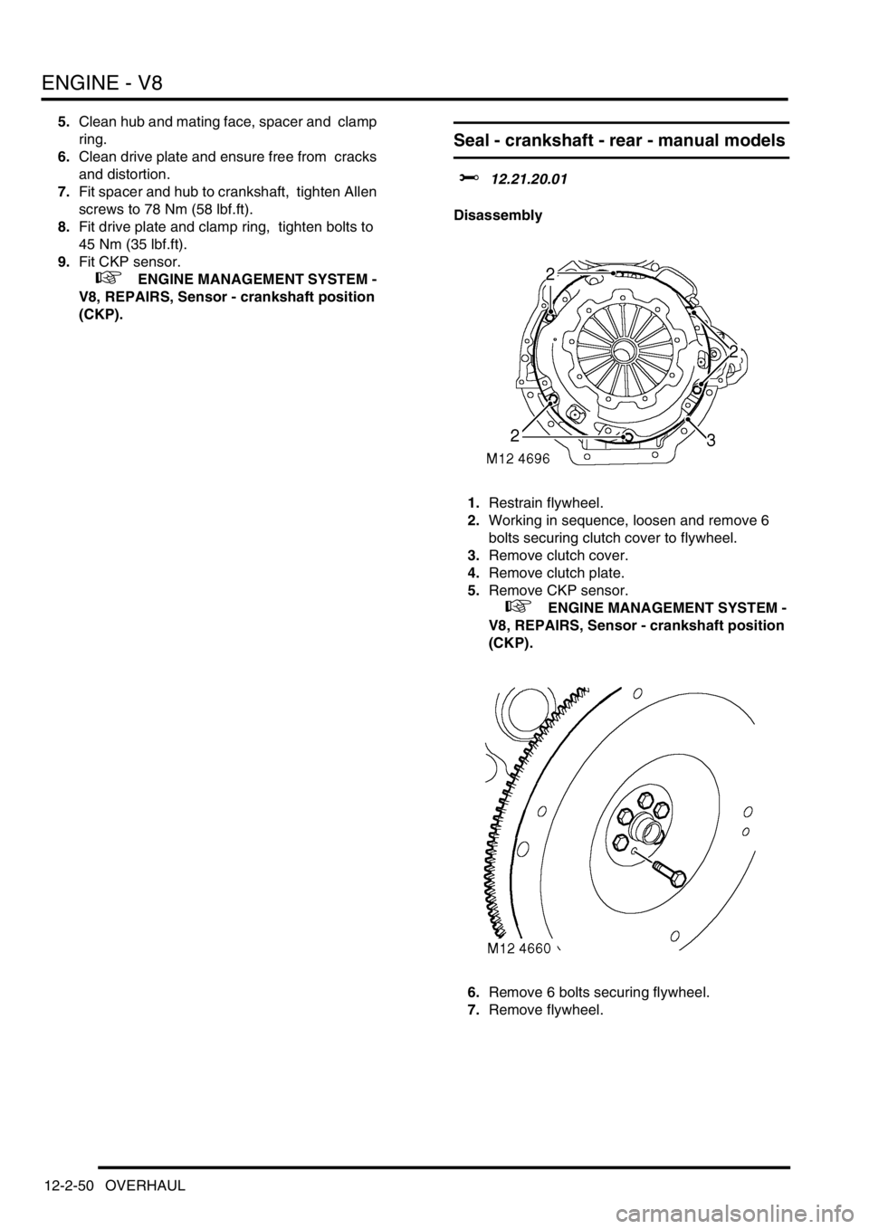
2.Working in sequence, loosen and remove 6
bolts securing clutch cover to flywheel.
3.Remove clutch cover.
4.Remove clutch plate.
5.Remove CKP sensor.
+ ENGINE MANAGEMENT SYSTEM -
V8, REPAIRS, Sensor - crankshaft position
(CKP).
6.Remove 6 bolts securing flywheel.
7.Remove flywheel.
Page 294 of 1672
ENGINE - V8
OVERHAUL 12-2-51
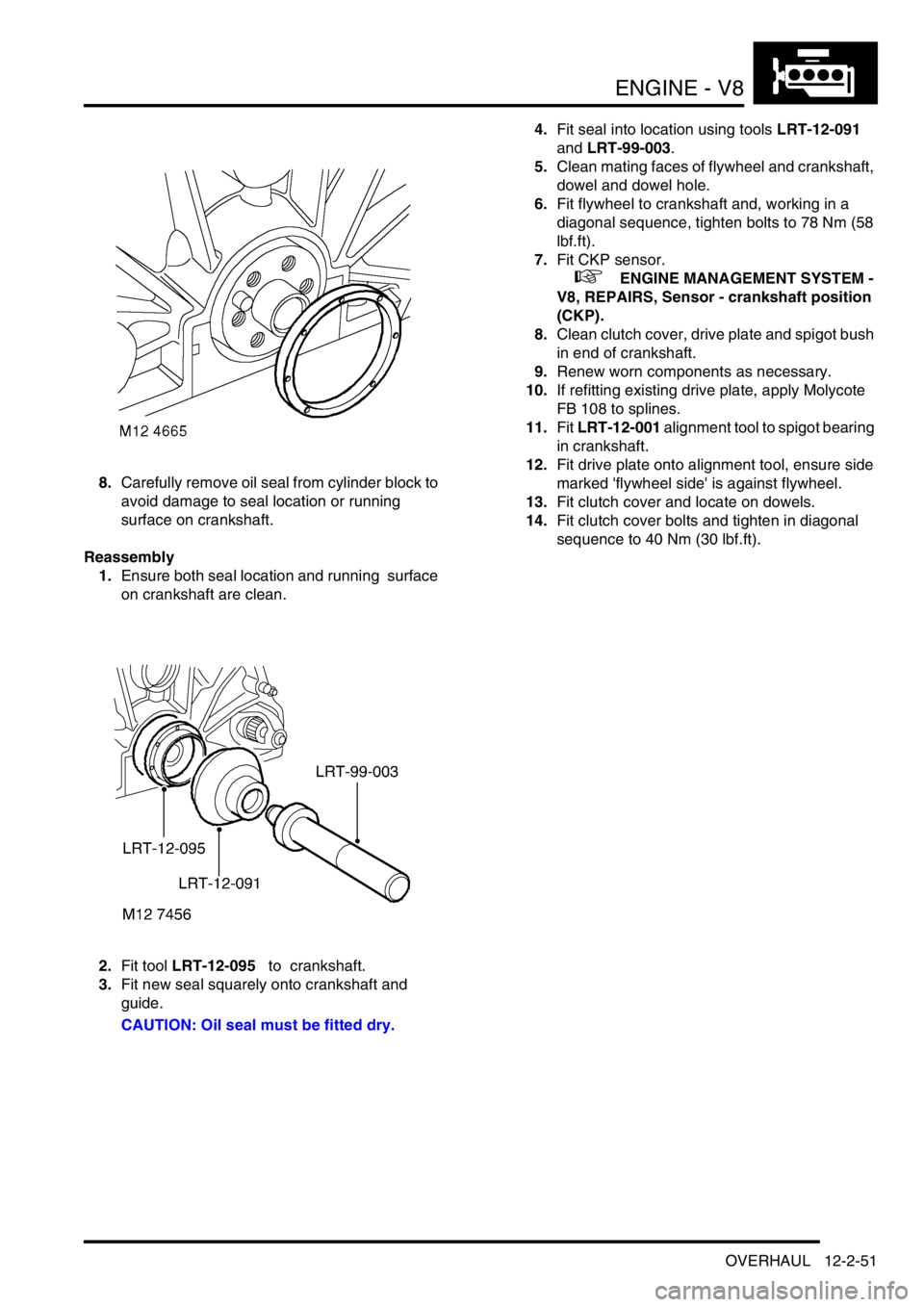
8.Carefully remove oil seal from cylinder block to
avoid damage to seal location or running
surface on crankshaft.
Reassembly
1.Ensure both seal location and running surface
on crankshaft are clean.
2.Fit tool LRT-12-095 to crankshaft.
3.Fit new seal squarely onto crankshaft and
guide.
CAUTION: Oil seal must be fitted dry.4.Fit seal into location using tools LRT-12-091
and LRT-99-003.
5.Clean mating faces of flywheel and crankshaft,
dowel and dowel hole.
6.Fit flywheel to crankshaft and, working in a
diagonal sequence, tighten bolts to 78 Nm (58
lbf.ft).
7.Fit CKP sensor.
+ ENGINE MANAGEMENT SYSTEM -
V8, REPAIRS, Sensor - crankshaft position
(CKP).
8.Clean clutch cover, drive plate and spigot bush
in end of crankshaft.
9.Renew worn components as necessary.
10.If refitting existing drive plate, apply Molycote
FB 108 to splines.
11.Fit LRT-12-001 alignment tool to spigot bearing
in crankshaft.
12.Fit drive plate onto alignment tool, ensure side
marked 'flywheel side' is against flywheel.
13.Fit clutch cover and locate on dowels.
14.Fit clutch cover bolts and tighten in diagonal
sequence to 40 Nm (30 lbf.ft).
Page 299 of 1672
ENGINE - V8
12-2-56 OVERHAUL
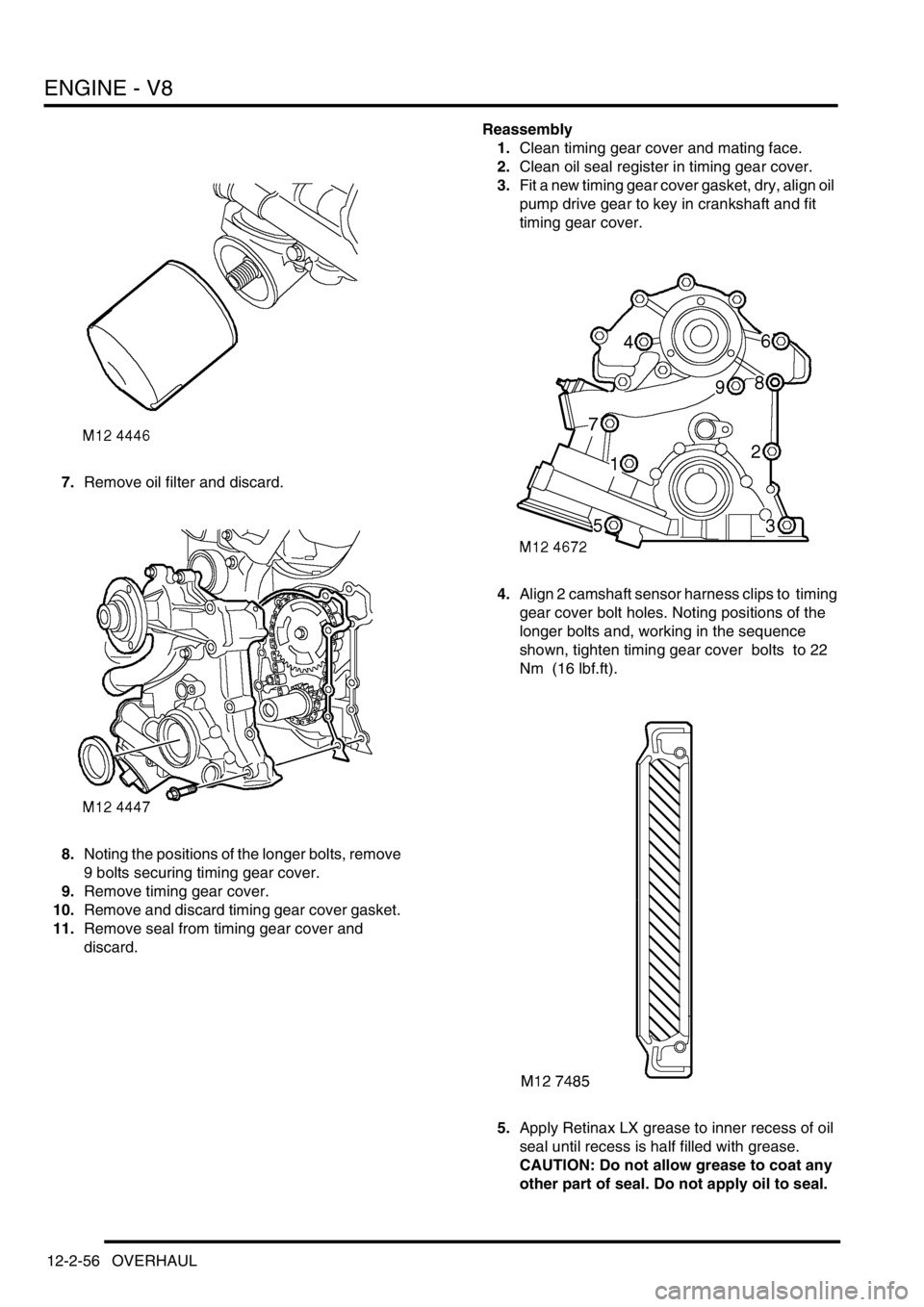
7.Remove oil filter and discard.
8.Noting the positions of the longer bolts, remove
9 bolts securing timing gear cover.
9.Remove timing gear cover.
10.Remove and discard timing gear cover gasket.
11.Remove seal from timing gear cover and
discard. Reassembly
1.Clean timing gear cover and mating face.
2.Clean oil seal register in timing gear cover.
3.Fit a new timing gear cover gasket, dry, align oil
pump drive gear to key in crankshaft and fit
timing gear cover.
4.Align 2 camshaft sensor harness clips to timing
gear cover bolt holes. Noting positions of the
longer bolts and, working in the sequence
shown, tighten timing gear cover bolts to 22
Nm (16 lbf.ft).
5.Apply Retinax LX grease to inner recess of oil
seal until recess is half filled with grease.
CAUTION: Do not allow grease to coat any
other part of seal. Do not apply oil to seal.
Page 326 of 1672
EMISSION CONTROL - TD5
DESCRIPTION AND OPERATION 17-1-5
Exhaust gas recirculation
The exhaust gas recirculation (EGR) valve permits a controlled amount of exhaust gas to combine with the fresh air
entering the engine. The exhaust gas reduces the combustion temperature by delaying the fuel burning rate, which
assists in reducing the quantity of oxides of nitrogen.
On EU3 models, an EGR cooler is employed to further reduce the combustion temperature. By passing the exhaust
gas through a bundle of pipes flooded by coolant, the density of the exhaust gas going into the engine is increased.
This process further reduces the amount of oxygen, which in turn, further reduces the amount of NO
2 in the exhaust.
Recirculating too much exhaust gas can result in higher emissions of soot, HC and CO due to insufficient air. The
recirculated exhaust gas must be limited so that there is sufficient oxygen available for combustion of the injected fuel
in the combustion chamber, to do this the Engine Control Module (ECM) is used to control the precise quantity of
exhaust gas to be recirculated in accordance with the prevailing operating conditions. Influencing factors include:
lthe mass of air flow detected by the mass air flow sensor.
+ ENGINE MANAGEMENT SYSTEM - Td5, DESCRIPTION AND OPERATION, Description.
lthe ambient air pressure, determined by the ambient air pressure sensor which is used to initiate adjustments
to reduce the amount of smoke produced at high altitudes.
+ ENGINE MANAGEMENT SYSTEM - Td5, DESCRIPTION AND OPERATION, Description.
Other factors which are taken into consideration by the engine management system for determining the optimum
operating condition include:
lManifold inlet air temperature
lCoolant temperature
lEngine speed
lFuel delivered
The main components of the EGR system are as follows.
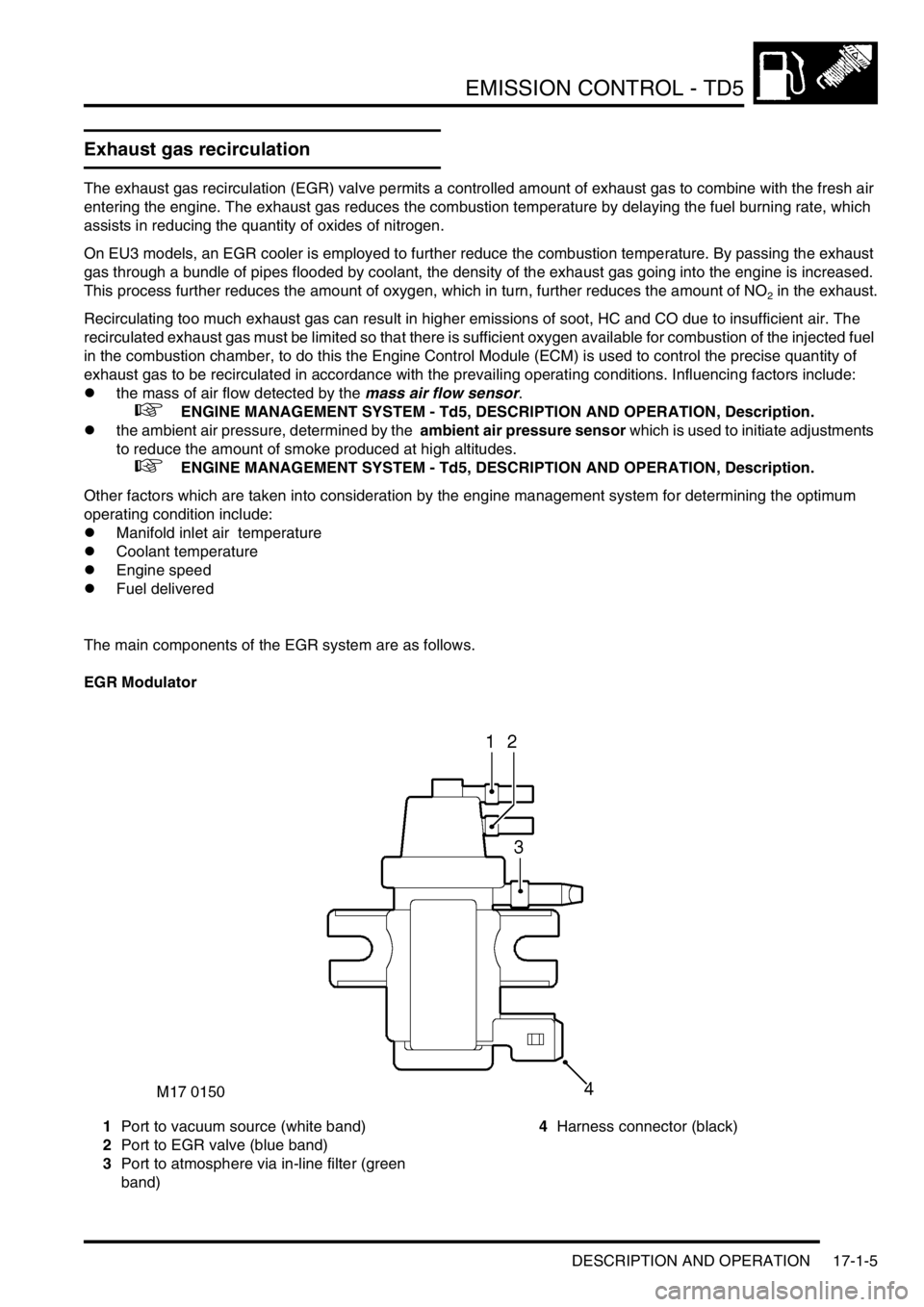
EGR Modulator
1Port to vacuum source (white band)
2Port to EGR valve (blue band)
3Port to atmosphere via in-line filter (green
band)4Harness connector (black)
Page 331 of 1672

EMISSION CONTROL - TD5
17-1-10 DESCRIPTION AND OPERATION
EGR systems
There are two types of exhaust gas recirculation system used with the Td5 engine dependent on legislation and
market requirements, these are type 1 and type 2.
Type 1 EGR system is fitted to all Td5's built up to the introduction of 2002 MY, except for Japanese specification
vehicles.
Type 2 EGR system is fitted to all Japanese specification vehicles and was introduced into European markets for 2002
MY to meet EU3 emission requirements. An additional feature introduced at 2002 MY is the EGR cooler, which is
bolted to the front of the cylinder head.
EGR system - type 1
This EGR system features a single modulator which is electrically controlled to modulate a vacuum source to the EGR
valve. The controlled vacuum opens and closes the valve by the amount required to ensure the optimal proportion of
exhaust gas is allowed through to the inlet manifold to be combined with the fresh air intake. Control feedback is
achieved by monitoring the mass of fresh air flowing through the mass air flow sensor.
The modulator operation is controlled by a signal from the ECM which determines the required amount of EGR
needed in response to inputs relating to air flow and engine operating and ambient conditions. The ECM is low-side
driven, sinking current returned from the vacuum modulator for switching operating condition.
The exhaust gases are routed from the exhaust manifold through a shaped metal pipe which connects to the
underside of the EGR valve. The pipe is held securely in position to the front of the cylinder head using a clamp
bracket. The EGR pipe is attached to a mating port at the front end of the exhaust manifold using two Allen screws
and at the EGR valve assembly by a metal band clamp. The two Allen screws fixing the EGR pipe to the exhaust
manifold should be replaced every time the EGR pipe is removed. Extreme care should be exercised when
removing and refitting the EGR pipe to avoid damage.
When a vacuum is applied to the EGR suction port, it causes a spindle with sealing disc (EGR valve) to be raised,
thus opening the port at the EGR pipe to allow the recirculated exhaust gas to pass through into the inlet manifold.
The valve is spring loaded so that when the vacuum is removed from the suction port the valve returns to its rest
position to tightly close the exhaust gas port.
By controlling the quantity of recirculated exhaust gas available in the inlet manifold, the optimum mix for the prevailing
engine operating conditions can be maintained, which ensures the intake gas to the combustion chambers will have
burning rate properties which will reduce the NO
x emissions to an acceptable level. Normally, full recirculation is only
applicable when the NO
x emissions are most prevalent.
EGR system - type 2
This system features twin modulators mounted one above the other on a metal plate located on the inner wing at the
RH side of the engine. The modulators are electrically controlled by the engine management system and are used to
modulate a vacuum source to the EGR valve and a supplementary Inlet Throttle (ILT) valve; the two valves are
controlled to operate in tandem. The ILT valve vacuum pot is mounted adjacent to the EGR valve housing and has a
linkage which connects to a butterfly valve mounted in front of the EGR valve at the air intake manifold.
The modulator operations are electrically controlled by signals from the engine management system which
determines the required volume of exhaust gas needed in response to inputs relating to air flow, engine operating
conditions and ambient parameters such as temperature and altitude. The engine management ECM switches on the
circuit by completing the path to ground, operating the vacuum modulators.
Pre EU3 models: The exhaust gases are routed from the exhaust manifold through a shaped metal pipe which
connects to the underside of the EGR valve. The pipe is held securely in position to the front of the engine cylinder
head using a metal clamp bracket. The EGR pipe is attached to a mating port at the front end of the exhaust manifold
using two Allen screws and at the EGR valve assembly by a metal band clamp. The two Allen screws fixing the EGR
pipe to the exhaust manifold should be replaced every time the EGR pipe is removed. Extreme care should be
exercised when removing and refitting the EGR pipe to avoid damage.
Page 339 of 1672
EMISSION CONTROL - V8
17-2-2 DESCRIPTION AND OPERATION
Exhaust emission control
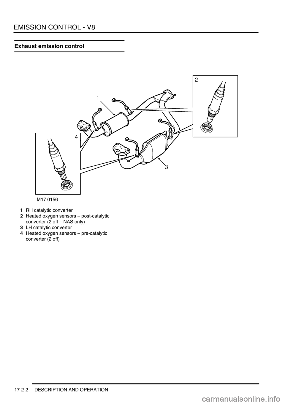
1RH catalytic converter
2Heated oxygen sensors – post-catalytic
converter (2 off – NAS only)
3LH catalytic converter
4Heated oxygen sensors – pre-catalytic
converter (2 off)
Page 340 of 1672
EMISSION CONTROL - V8
DESCRIPTION AND OPERATION 17-2-3
Evaporative emission system
component layout
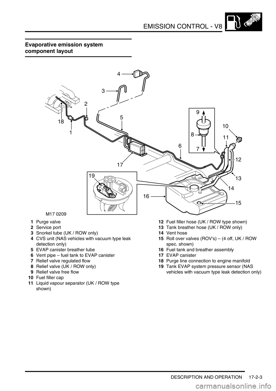
1Purge valve
2Service port
3Snorkel tube (UK / ROW only)
4CVS unit (NAS vehicles with vacuum type leak
detection only)
5EVAP canister breather tube
6Vent pipe – fuel tank to EVAP canister
7Relief valve regulated flow
8Relief valve (UK / ROW only)
9Relief valve free flow
10Fuel filler cap
11Liquid vapour separator (UK / ROW type
shown)12Fuel filler hose (UK / ROW type shown)
13Tank breather hose (UK / ROW only)
14Vent hose
15Roll over valves (ROV's) – (4 off, UK / ROW
spec. shown)
16Fuel tank and breather assembly
17EVAP canister
18Purge line connection to engine manifold
19Tank EVAP system pressure sensor (NAS
vehicles with vacuum type leak detection only)
M17 0209
4
3
1
6
5
16
10
8
13
17
9
7
11
12
15
14
18
2
19
Page 342 of 1672
EMISSION CONTROL - V8
DESCRIPTION AND OPERATION 17-2-5
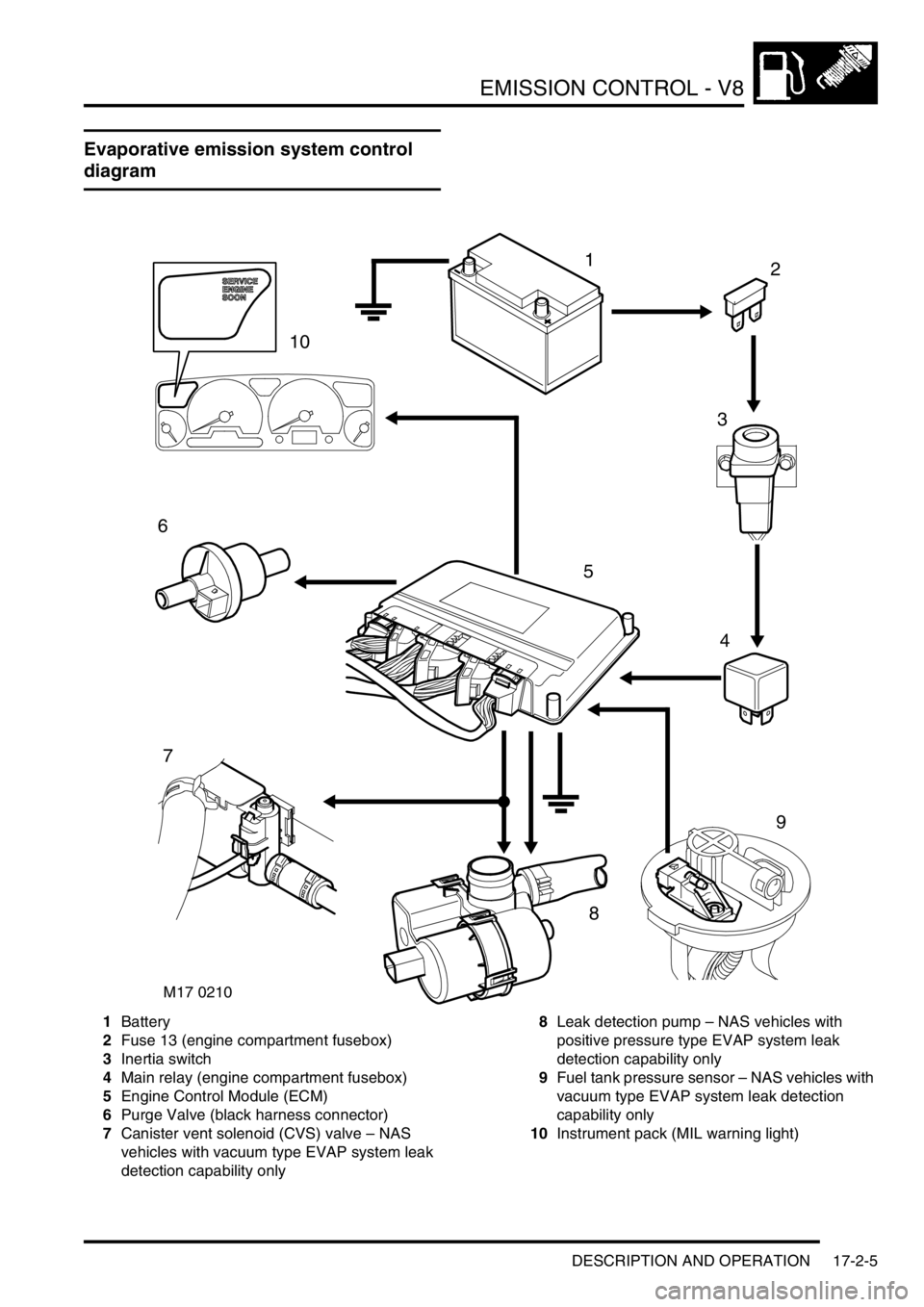
Evaporative emission system control
diagram
1Battery
2Fuse 13 (engine compartment fusebox)
3Inertia switch
4Main relay (engine compartment fusebox)
5Engine Control Module (ECM)
6Purge Valve (black harness connector)
7Canister vent solenoid (CVS) valve – NAS
vehicles with vacuum type EVAP system leak
detection capability only8Leak detection pump – NAS vehicles with
positive pressure type EVAP system leak
detection capability only
9Fuel tank pressure sensor – NAS vehicles with
vacuum type EVAP system leak detection
capability only
10Instrument pack (MIL warning light)
M17 0210
12
3
4
5
6
7
9
8
10