engine LAND ROVER DISCOVERY 2002 Workshop Manual
[x] Cancel search | Manufacturer: LAND ROVER, Model Year: 2002, Model line: DISCOVERY, Model: LAND ROVER DISCOVERY 2002Pages: 1672, PDF Size: 46.1 MB
Page 953 of 1672

FRONT SUSPENSION
60-14 DESCRIPTION AND OPERATION
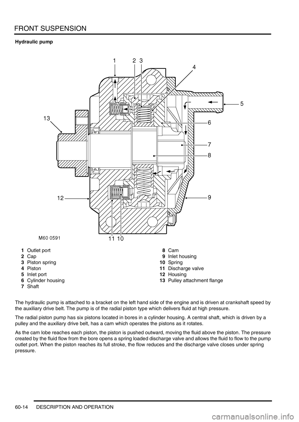
Hydraulic pump
1Outlet port
2Cap
3Piston spring
4Piston
5Inlet port
6Cylinder housing
7Shaft8Cam
9Inlet housing
10Spring
11Discharge valve
12Housing
13Pulley attachment flange
The hydraulic pump is attached to a bracket on the left hand side of the engine and is driven at crankshaft speed by
the auxiliary drive belt. The pump is of the radial piston type which delivers fluid at high pressure.
The radial piston pump has six pistons located in bores in a cylinder housing. A central shaft, which is driven by a
pulley and the auxiliary drive belt, has a cam which operates the pistons as it rotates.
As the cam lobe reaches each piston, the piston is pushed outward, moving the fluid above the piston. The pressure
created by the fluid flow from the bore opens a spring loaded discharge valve and allows the fluid to flow to the pump
outlet port. When the piston reaches its full stroke, the flow reduces and the discharge valve closes under spring
pressure.
Page 954 of 1672

FRONT SUSPENSION
DESCRIPTION AND OPERATION 60-15
As the cam lobe moves away from the piston, a spring pushes the piston down the bore creating a vacuum above the
piston. As the piston moves down the bore, ports in the piston are exposed and connect with the fluid inlet. The
vacuum draws fluid into the piston filling the piston and the chamber above it. As the piston is again pushed upwards,
the ports are closed off by the bore and the fluid opens the discharge valve and flows to the outlet port.
The above sequence is applied to each of the six pistons for every revolution of the central shaft and cam. When the
engine is running the sequence occurs rapidly creating a constant flow of fluid. The fluid flow varies with the engine
speed and the rotational speed of the central shaft. The pressure felt at the actuator, created by the flow from the
pump, is controlled by the pressure control valve in the valve block.
The pump has a displacement of 8.5 cm
3/rev and an operational pressure of 135 bar (1958 lbf.in2). The pump output
flow ranges from 7.0 l/min (1.85 US Gallons/min) at 775 rev/min to 9.25 l/min (2.44 US Gallons/min) at 7625 rev/min.
System pipes
Fluid is moved through the ACE system via a series of pipes and hoses. The pipes are mounted on brackets at
strategic points to assure quiet operation of the system.
The pipes from the pump to the valve block and from the valve block to the reservoir are one piece items which are
fitted at the factory before the body is attached to the chassis. If these pipes require replacement in service, the pipes
must be cut to facilitate their removal. 'In service' replacement pipes are available in two parts with a connector to seal
the joint.
The flexible hose which supplies pressure from the pump to the supply pipe attached to the front cross member is
fitted with an attenuator. The attenuator comprises a bullet shaped valve which is located between two spiral wound
springs held at each end of the flexible hose. This valve operates as a restrictor to damp pressure waves of hydraulic
fluid from the pump, reducing noise and strain on components downstream. The attenuator is integral with the supply
hose and pipe and cannot be serviced separately.
Page 959 of 1672

FRONT SUSPENSION
60-20 DESCRIPTION AND OPERATION
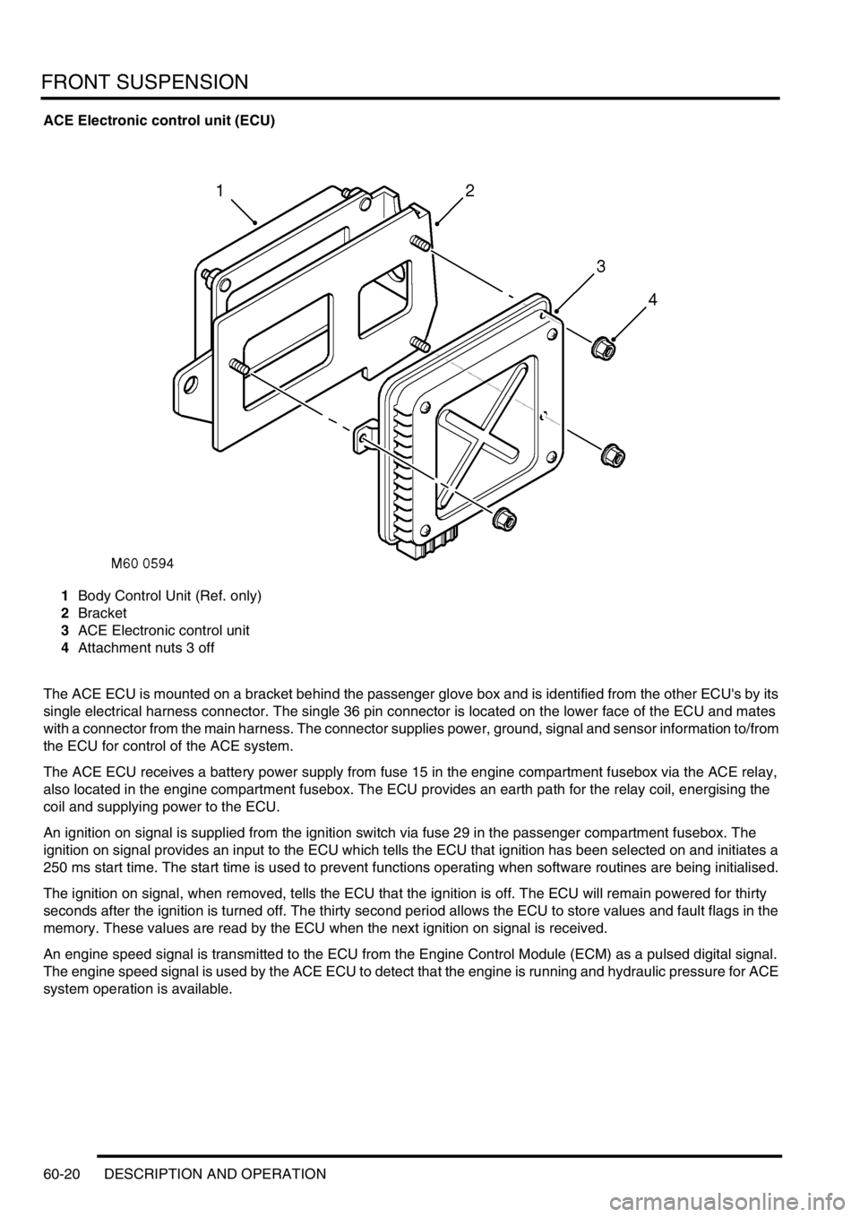
ACE Electronic control unit (ECU)
1Body Control Unit (Ref. only)
2Bracket
3ACE Electronic control unit
4Attachment nuts 3 off
The ACE ECU is mounted on a bracket behind the passenger glove box and is identified from the other ECU's by its
single electrical harness connector. The single 36 pin connector is located on the lower face of the ECU and mates
with a connector from the main harness. The connector supplies power, ground, signal and sensor information to/from
the ECU for control of the ACE system.
The ACE ECU receives a battery power supply from fuse 15 in the engine compartment fusebox via the ACE relay,
also located in the engine compartment fusebox. The ECU provides an earth path for the relay coil, energising the
coil and supplying power to the ECU.
An ignition on signal is supplied from the ignition switch via fuse 29 in the passenger compartment fusebox. The
ignition on signal provides an input to the ECU which tells the ECU that ignition has been selected on and initiates a
250 ms start time. The start time is used to prevent functions operating when software routines are being initialised.
The ignition on signal, when removed, tells the ECU that the ignition is off. The ECU will remain powered for thirty
seconds after the ignition is turned off. The thirty second period allows the ECU to store values and fault flags in the
memory. These values are read by the ECU when the next ignition on signal is received.
An engine speed signal is transmitted to the ECU from the Engine Control Module (ECM) as a pulsed digital signal.
The engine speed signal is used by the ACE ECU to detect that the engine is running and hydraulic pressure for ACE
system operation is available.
Page 961 of 1672

FRONT SUSPENSION
60-22 DESCRIPTION AND OPERATION
Failure modes
Failures where the vehicle can still be driven safely are indicated by the ACE warning lamp illuminating continuously
with an amber colour. The amber warning lamp will remain illuminated until the ignition is turned off. For all faults the
warning lamp will only illuminate again if the fault is still present. Failures which require the driver to stop the vehicle
immediately are indicated by the ACE warning lamp flashing with a red colour and an audible warning. All faults are
recorded by the ACE ECU and can be retrieved with diagnostic equipment.
The following tables show the type of system failures and their effects on the system operation. Torsion bar 'floppy'
means that fluid is allowed to circulate freely through the system. With no pressure in the actuators the torsion bar will
have no effect on vehicle roll. 'Locked bars' means that all pump flow is directed through the valve block and returns
to the reservoir. Both DCV's close and fluid is trapped in the actuators but can flow from one actuator to the other via
the valve block. In this condition the torsion bar will perform similar to a conventional anti-roll bar, resisting roll but still
allowing the axles to articulate.
Acceleration sensors
Pressure transducer
14 Reverse switch Input
15 Accelerometer - lower (signal) Input
16 Pressure transducer (signal) Input
17 Accelerometer - upper (signal) Input
18 Accelerometer - upper (supply) Output
19 Engine speed Input
20 Main earth 1 -
21 Pressure transducer (earth) Input
22 DCV 2 (earth) Input
23 DCV 1 (earth) Input
24 DCV 1 & 2 (supply) Output
25 Pressure control valve (earth) Input
26 Not used -
27 Pressure control valve (supply) Output
28 Main supply (+ V Batt) Input
29 to 31 Not used -
32 Main earth 2 -
33 Accelerometer - lower (signal) Input
34 Accelerometer - upper (signal) Input
35 Not used -
36 Warning lamp Output
Failure Effect
Valve stuck closed No ACE control
Short circuit - Ground No ACE control
Short circuit - VBatt No ACE control
Loose sensor Erractic ACE activity when driving in straight line
Failure Effect
Short circuit - VBatt Large sensor dead band - possible random movementsPin No. Description Input/Output
Page 962 of 1672

FRONT SUSPENSION
DESCRIPTION AND OPERATION 60-23
Road speed signal
Engine speed signal
Reverse gear signal
Ignition ON signal
Pressure control valve failure
Failure Effect
Open circuit No ACE control - 'Locked bars' condition
Short circuit - Ground No ACE control - 'Locked bars' condition
Short circuit - VBatt No ACE control - 'Locked bars' condition
Failure Effect
Open circuit No ACE control - 'Locked bars' condition
Short circuit - Ground No ACE control - 'Locked bars' condition
Short circuit - VBatt No ACE control - 'Locked bars' condition
Failure Effect
Open circuit No reverse signal to ECU. ACE active in reverse, may give
abnormal handling when reversing
Short circuit - Ground No reverse signal to ECU. ACE active in reverse, may give
abnormal handling when reversing
Short circuit - VBatt Permanent reverse signal to ECU. Permanent 'Locked
bars' condition
Failure Effect
Open circuit ECU does not receive ignition ON signal. No ARC control,
'Locked bars' condition
Short circuit - Ground ECU does not receive ignition ON signal. No ARC control,
'Locked bars' condition
Short circuit - VBatt Permanent ignition ON signal to ECU. Possibility of flat
battery
Failure Effect
Open circuit No ACE control
Short circuit - Ground No ACE control
Short circuit - VBatt No ACE control
Valve stuck open No ACE control
Valve stuck closed Maximum system pressure - no proportional control.
Pressure relief valve operating at 185 bar (2683 lbf.in
2)
Page 964 of 1672

FRONT SUSPENSION
DESCRIPTION AND OPERATION 60-25
Operation
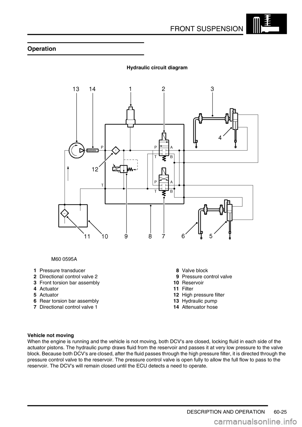
Hydraulic circuit diagram
1Pressure transducer
2Directional control valve 2
3Front torsion bar assembly
4Actuator
5Actuator
6Rear torsion bar assembly
7Directional control valve 18Valve block
9Pressure control valve
10Reservoir
11Filter
12High pressure filter
13Hydraulic pump
14Attenuator hose
Vehicle not moving
When the engine is running and the vehicle is not moving, both DCV's are closed, locking fluid in each side of the
actuator pistons. The hydraulic pump draws fluid from the reservoir and passes it at very low pressure to the valve
block. Because both DCV's are closed, after the fluid passes through the high pressure filter, it is directed through the
pressure control valve to the reservoir. The pressure control valve is open fully to allow the full flow to pass to the
reservoir. The DCV's will remain closed until the ECU detects a need to operate.
Page 966 of 1672

FRONT SUSPENSION
ADJUSTMENTS 60-27
ADJUST ME NTS
ACE hydraulic system bleeding
$% 60.60.13
Introduction
CAUTION: The ACE hydraulic system is
extremely sensitive to the ingress of dirt or
debris. The smallest amount could render the
system unserviceable. It is imperative that the
following precautions are taken.
lACE components are thoroughly cleaned
externally before work commences;
lall opened pipe and module ports are
capped immediately;
lall fluid is stored in and administered
through clean containers.
Check
1.Check the ACE system fluid level.
+ FRONT SUSPENSION,
ADJUSTMENTS, Fluid level check - ACE
system.
Bleed
1.With vehicle on ramp, connect TestBook and
follow bleed procedure as described.
Fluid level check - ACE system
$% 60.60.14
Introduction
CAUTION: The ACE hydraulic system is
extremely sensitive to the ingress of dirt or
debris. The smallest amount could render the
system unserviceable. It is imperative that the
following precautions are taken.
lACE components are thoroughly cleaned
externally before work commences;
lall opened pipe and module ports are
capped immediately;
lall fluid is stored in and administered
through clean containers.
Check
1.Clean reservoir around fluid level marks.
2.Visually check fluid level through side of
reservoir. Fluid level must be between upper
and lower fluid level marks.
Top-up
1.Clean reservoir around filler cap.
2.Remove filler cap from reservoir and fill to
upper fluid level mark with recommended fluid.
+ CAPACITIES, FLUIDS AND
LUBRICANTS, Fluids.
3.Fit filler cap to reservoir
4.Start and run engine for 2 minutes to circulate
fluid.
5.If necessary, top-up reservoir to upper fluid
level mark.
Page 977 of 1672

FRONT SUSPENSION
60-38 REPAIRS
5.Remove 4 nuts securing turret base to chassis.
6.Remove 2 bolts securing damper to axle.
7. ACE models: Remove bolt securing ACE pipe
clamp to chassis.
8. ACE models: Remove bolt securing ACE pipe
clamp to turret.
9.Release harness clip from turret.
10.Raise turret and remove through bolt.
11.Compress damper and manoeuvre turret from
engine bay.
12.Remove damper. Refit
1.Position damper and manoeuvre turret into
position. Raise damper and align to turret. Fit
through bolt but do not tighten at this stage.
2.Align damper assembly to spring seat.
3.Fit bolts securing damper to axle and tighten to
45 Nm (33 lbf.ft).
4.Fit nuts securing turret to chassis and tighten
to 23 Nm (17 lbf.ft).
5.Tighten through bolt to 125 Nm (92 lbf.ft).
6. ACE models: Position ACE pipe clamp to
chassis and secure with bolt.
7. ACE models: Position ACE pipe clamp to
turret and secure with bolt.
8.Secure harness to turret.
9. RH damper: Reposition coolant reservoir.
10.Fit road wheel and tighten nuts to 140 Nm (103
lbf.ft).
11.Remove stand(s) and lower vehicle.
Page 988 of 1672

FRONT SUSPENSION
REPAIRS 60-49
Refit
1.Ensure new filter has 'O' ring fitted, then fit filter
to valve block.
2.Fit new 'O' ring to filter cap. Fit cap and tighten
to 35 Nm (26 lbf.ft).
3.Lower vehicle.
4.Check fluid level in ACE/PAS reservoir.
+ FRONT SUSPENSION,
ADJUSTMENTS, Fluid level check - ACE
system.
5.Start and run engine for 2 minutes, then re-
check fluid level in ACE/PAS reservoir.
+ FRONT SUSPENSION,
ADJUSTMENTS, Fluid level check - ACE
system.
Pressure transducer - ACE
$% 60.60.22
CAUTION: The ACE hydraulic system is
extremely sensitive to the ingress of dirt or
debris. The smallest amount could render the
system unserviceable. It is imperative that the
following precautions are taken.
lACE components are thoroughly cleaned
externally before work commences;
lall opened pipe and module ports are
capped immediately;
lall fluid is stored in and administered
through clean containers.
Remove
1.Raise vehicle on a ramp.
2.Disconnect multiplug from transducer.
3.Position container to collect fluid spillage.
4.Remove pressure transducer and discard 'O'
ring.
CAUTION: Always fit plugs to open
connections to prevent contamination.
Page 1016 of 1672

REAR SUSPENSION
DESCRIPTION AND OPERATION 64-11
1Battery supply (via SLABS relay)
2Ignition supply
3RH height sensor
4LH height sensor
5Off-road mode warning lamp
6Audible warning speaker
7Instrument pack
8SLS warning lamp
9Fusible link 9
10SLS relay
11Air supply unit12RH air valve
13LH air valve
14Exhaust valve
15Diagnostic socket
16Off-road mode switch
17SLS remote handset
18Body Control Unit (BCU)
19Door switches
20SLABS ECU
21Engine Control Module (ECM)