engine LAND ROVER DISCOVERY 2002 Workshop Manual
[x] Cancel search | Manufacturer: LAND ROVER, Model Year: 2002, Model line: DISCOVERY, Model: LAND ROVER DISCOVERY 2002Pages: 1672, PDF Size: 46.1 MB
Page 1063 of 1672

BRAKES
70-18 DESCRIPTION AND OPERATION
The SLABS ECU continually calculates vehicle speed using the wheel speed inputs from all four ABS sensors. The
calculated vehicle speed is then used as a reference against which individual wheel speeds are monitored for
unacceptable acceleration or deceleration. The ABS sensor inputs are also used by the SLABS ECU to detect vehicle
deceleration rate, vehicle cornering rate and rough terrain.
The engaged forward gear and (on manual gearbox models) the clutch status are computed from the engine data
input, the engine speed input and vehicle speed. Reverse gear status is provided by an input from the reverse lamp
switch (manual gearbox models) or the BCU (automatic gearbox models). On automatic models, the BCU also
provides the neutral selected input.
In addition to controlling the brake related functions, the SLABS ECU:
lControls the operation of the self levelling suspension (SLS) system (where fitted).
+ REAR SUSPENSION, DESCRIPTION AND OPERATION, Description.
lOn V8 models, outputs a rough road signal to the ECM when traversing rough terrain.
lOutputs a vehicle speed signal.
The vehicle speed signal is output to the following systems (where fitted):
lActive Cornering Enhancement.
+ FRONT SUSPENSION, DESCRIPTION AND OPERATION, Description - ACE.
lAir conditioning.
+ AIR CONDITIONING, DESCRIPTION AND OPERATION, Description.
lCruise control.
+ ENGINE MANAGEMENT SYSTEM - Td5, DESCRIPTION AND OPERATION, Description.
+ ENGINE MANAGEMENT SYSTEM - V8, DESCRIPTION AND OPERATION, Description - engine
management.
lEngine management.
+ ENGINE MANAGEMENT SYSTEM - Td5, DESCRIPTION AND OPERATION, Description.
+ ENGINE MANAGEMENT SYSTEM - V8, DESCRIPTION AND OPERATION, Description - engine
management.
lIn-car entertainment.
+ IN CAR ENTERTAINMENT, DESCRIPTION AND OPERATION, Description.
lInstrument pack.
+ INSTRUMENTS, DESCRIPTION AND OPERATION, Description.
ABS sensors
The ABS sensors supply the SLABS ECU with a sinusoidal speed signal from each wheel. An inductive sensor,
installed in the hub bearing of each wheel, senses off a 60 tooth exciter ring integrated into the inner race of the hub
bearing. Each ABS sensor has a fly-lead connecting it to the vehicle wiring.
6 Shuttle valve switches Input
7 Rear left outlet solenoid valve Output
8 Rear left inlet solenoid valve Output
9 Centre differential lock switch Input
10 Rear right outlet solenoid valve Output
11 Rear right inlet solenoid valve Output
12 Brake lamp relay Output
15 Return pump relay Output
C0655
7 Audible warning Output
10 Engine speed Input
Connector and pins not listed are either not used or used by the self levelling suspension system.
+ REAR SUSPENSION, DESCRIPTION AND OPERATION, Description.
Connector/Pin No. Description Input/Output
Page 1066 of 1672

BRAKES
DESCRIPTION AND OPERATION 70-21
ETC
The ETC function uses brake intervention to prevent wheel spin and maintain even torque distribution to the wheels.
ETC is automatically enabled while the brakes are off at speeds up to 62.5 mph (100 km/h), and operates the brakes
either individually or in axle pairs:
lAt speeds up to 31.3 mph (50 km/h), ETC uses individual brake intervention to maintain even torque distribution
between wheels on the same axle.
lVehicles up to 03 model year – At speeds between 0 and 62.5 mph (0 and 100 km/h), ETC also uses brake
intervention in axle pairs to maintain even torque distribution between the front and rear axles. In effect, this mode
of operation replaces the centre differential lock of the transfer box which, although still incorporated, is non
operational under normal driving conditions.
+ TRANSFER BOX - LT230SE, DESCRIPTION AND OPERATION, Description. If the centre differential
lock is in the locked condition, the SLABS ECU illuminates the ABS and ETC warning lamps and inhibits the ETC
function (the ABS, EBD and HDC functions are retained, but at degraded performance levels).
lVehicles from 03 model year (with differential lock fitted) – At speeds between 0 and 62.5 mph (0 and 100
km/h), ETC uses brake intervention in axle pairs to maintain even torque distribution between the front and rear
axles. If the centre differential lock is in the locked condition, the differential lock warning lamp in the instrument
pack is illuminated. The ABS, EBD, ETC and HDC functions are retained, but with revised parameters to suit the
locked differential.
While the ETC function is enabled, if the SLABS ECU detects a wheel accelerating faster than the average, indicating
loss of traction, it operates the ABS modulator in the active braking mode. Depending on the vehicle speed, active
braking is employed for either the brake of the affected wheel or for both brakes on the affected axle, until all four
wheels are driven at approximately the same speed again. During active braking the SLABS ECU also illuminates the
ETC warning lamp, for a minimum of 2 seconds or for the duration that ETC is active. ETC operation is desensitised
during 'hard' cornering.
HDC
HDC uses brake intervention to provide a controlled descent ability in off road conditions when engine braking is
insufficient to maintain a comfortable speed. This allows the driver to leave HDC selected and to control the vehicle's
descent speed, down to the system's minimum target speed, using only the accelerator pedal. The HDC function is
selected on/off by a switch on the fascia. When selected on, HDC is enabled in all forward gears and reverse provided:
lVehicle speed is below 31.3 mph (50 km/h).
lThe transfer box is in low range.
lOn manual gearbox vehicles, the clutch is engaged.
When HDC is enabled, the HDC information warning lamp illuminates. If HDC is selected outside the above
conditions, the HDC information warning lamp flashes and the audible warning sounds continuously.
When HDC is enabled, the SLABS ECU calculates a target speed from the throttle position element of the engine data
input, and compares this with actual speed. If the actual speed is higher than the target speed, the SLABS ECU
operates the ABS modulator in the active braking mode to slow the vehicle down to the target speed. While the braking
force is being applied, the SLABS ECU also energizes the brake lamp relay to put the brake lamps on. Active braking
is discontinued while vehicle speed is below the target speed or if the foot brakes are applied. Applying the foot brakes
during active braking may result in a pulse through the brake pedal, which is normal.
During active braking, the brakes are operated predominantly on the wheels of the leading axle, but if that is not
sufficient to achieve the required deceleration the brakes of the trailing axle are also applied. The deceleration rate is
dependent on the speed differential between initial vehicle speed and the target speed. The deceleration rates are
relatively low at higher speed differentials, then progressively increase as vehicle speed approaches the target speed.
Anti-lock braking is also enabled during active braking, but at very low speeds some wheel lock can occur.
The target speed increases as the accelerator pedal is pressed, from a programmed minimum with the accelerator
pedal released, up to a maximum of 31.3 mph (50 km/h). For any given accelerator pedal position, while travelling
uphill or on level ground the target speed is always greater than the corresponding vehicle speed, which allows the
vehicle to be driven normally without HDC intervention. However, when travelling downhill, the gravitational effect on
the vehicle means that for any given accelerator pedal position the target speed is less than the corresponding vehicle
speed, and HDC intervenes to limit vehicle speed to the target speed.
Page 1068 of 1672

BRAKES
DESCRIPTION AND OPERATION 70-23
Typical disabled times
Diagnostics
While the ignition is on, the diagnostics function of the SLABS ECU monitors the system for faults. In addition, the
return pump is tested by pulsing it briefly immediately after the engine starts provided vehicle speed exceeded 4.4
mph (7 km/h) during the previous ignition cycle. If a fault exists in a warning lamp circuit, the lamp will not illuminate
during the lamp check at ignition on but, provided there are no other faults, the related function will otherwise be fully
operational. If a fault is detected during the power up, the SLABS ECU stores a related fault code in memory and
illuminates the appropriate fault warning lamps. If a fault is detected later in the drive cycle, the SLABS ECU also
sounds the audible warning three times.
Fault codes and diagnostic routines can be accessed by connecting Testbook to the vehicle's diagnostic connector
in the driver's footwell.
Warning lamp fault operation
After detecting a fault, the SLABS ECU selects an appropriate default strategy which, where possible, retains some
operational capability. A shuttle valve switch fault and throttle position signal fault are classified as permanent faults.
If a permanent fault is detected, the related warning lamp illumination and default strategies are automatically
employed in subsequent ignition cycles, even if the fault is intermittent, until the fault has been rectified and cleared
from memory. If a non permanent fault is detected, the related warning lamp illumination and default strategies will
only be employed in subsequent ignition cycles if the fault is still present.
After rectification of an ABS sensor fault, the ABS and ETC functions are disabled, and the ABS warning lamp remains
illuminated after the lamp check, until vehicle speed exceeds 9.4 mph (15 km/h) (to allow additional checks to be
performed).
Vehicle speed, mph (km/h) Time, minutes
1.3 (2) 40
12.5 (20) 33
15.6 (25) 17
25.0 (40) 9
31.3 (50) 6
Item Check Warning lamp
ABS Brake ETC HDC
fault
ABS sensors Resistance (to check status) On On On On
Brake lamps relay Open/Short circuit Off Off Off On
Engine data Sticking throttle, signal failure, data corruption Off Off On On
Inlet solenoid valves Open/Short circuit On On On On
Outlet solenoid valves Open/Short circuit On On On On
Reference earth Connection to earth On On On On
Return pump monitor Correct pump operation On On On On
Return pump relay Open/Short circuit On On On On
Shuttle valve switches Open/Short circuit On On On On
SLABS ECU Internal failure On On On On
Supply voltages Range (10 to 16 V) On On On On
Page 1088 of 1672

BRAKES
REPAIRS 70-43
Refit
1.Clean mating faces of alternator and vacuum
pump.
2.Fit vacuum pump to alternator and tighten
bolts to 8 Nm (6 lbf.ft).
3.Position alternator to engine and connect
multiplug.
4.Connect vacuum hose and oil drain hose to
vacuum pump and secure clips.
5.With assistance align alternator to mounting
bracket and fit but do not tighten bolt.
6.Fit bolt securing support stay to alternator and
tighten to 25 Nm (18 lbf.ft) .
7.Tighten bolt securing alternator to mounting
bracket to 45 Nm (33 lbf.ft).
8.Using new 'O' ring, connect oil supply pipe to
cylinder head and tighten to 10 Nm (7 lbf.ft).
9.Connect lead to alternator and tighten nut to 6
Nm (4.4 lbf.ft).
10.Fit auxiliary drive belt tensioner and tighten bolt
to 50 Nm (37 lbf.ft).
11.Fit auxiliary drive belt.
+ CHARGING AND STARTING,
REPAIRS, Belt - auxiliary drive.
Housing - caliper - front
$% 70.55.24
Remove
1.Raise front of vehicle, one side.
WARNING: Do not work on or under a
vehicle supported only by a jack. Always
support the vehicle on safety stands.
2.Remove road wheel(s).
3.Clamp brake hose to prevent fluid loss.
4.Remove brake hose banjo bolt and discard
sealing washers.
CAUTION: Always fit plugs to open
connections to prevent contamination.
5.Remove 2 guide pin bolts and remove caliper
housing from carrier.
6.Remove 2 brake pads from caliper carrier.
Page 1105 of 1672

RESTRAINT SYSTEMS
75-10 DESCRIPTION AND OPERATION
SRS warning lamp
The SRS warning lamp illuminates for 5 seconds during system readiness check on starting the engine. The SRS
warning lamp extinguishes for one second after the system readiness check is performed. If a fault is present the
warning lamp then illuminates continuously. If no fault is present, the SRS warning lamp remains extinguished. If a
system fault occurs in excess of two seconds after the readiness check has been completed, the SRS warning lamp
illuminates for that ignition cycle. It remains illuminated for a minimum of 12 seconds
± 4 seconds for all fault
conditions.
The SRS warning lamp will only illuminate for low voltage concerns while the low voltage condition is present. If the
low voltage condition is corrected, the SRS warning lamp extinguishes and the fault is recorded in the DCU's memory.
Page 1147 of 1672

EXTERIOR FITTINGS
76-2-10 REPAIRS
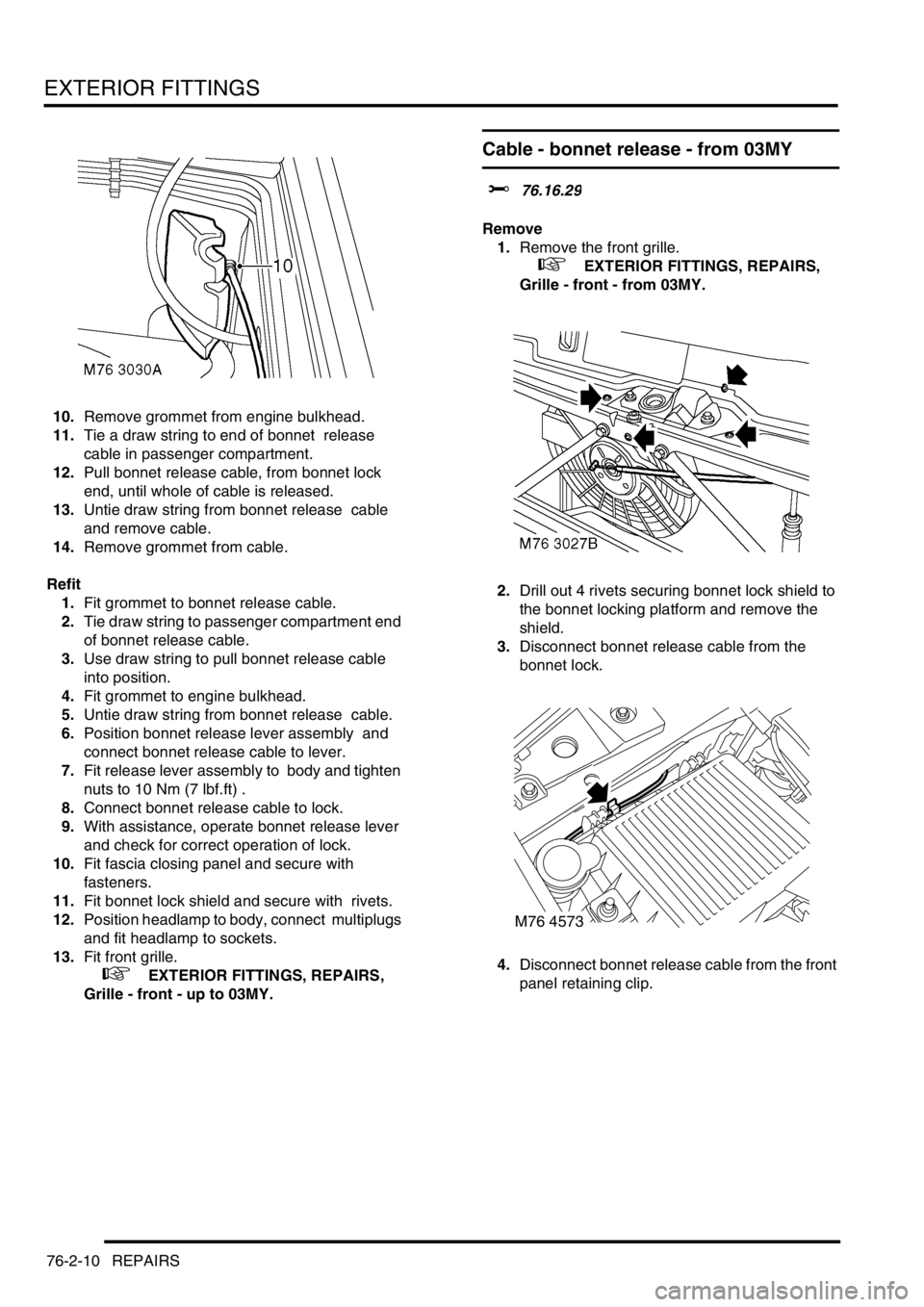
10.Remove grommet from engine bulkhead.
11.Tie a draw string to end of bonnet release
cable in passenger compartment.
12.Pull bonnet release cable, from bonnet lock
end, until whole of cable is released.
13.Untie draw string from bonnet release cable
and remove cable.
14.Remove grommet from cable.
Refit
1.Fit grommet to bonnet release cable.
2.Tie draw string to passenger compartment end
of bonnet release cable.
3.Use draw string to pull bonnet release cable
into position.
4.Fit grommet to engine bulkhead.
5.Untie draw string from bonnet release cable.
6.Position bonnet release lever assembly and
connect bonnet release cable to lever.
7.Fit release lever assembly to body and tighten
nuts to 10 Nm (7 lbf.ft) .
8.Connect bonnet release cable to lock.
9.With assistance, operate bonnet release lever
and check for correct operation of lock.
10.Fit fascia closing panel and secure with
fasteners.
11.Fit bonnet lock shield and secure with rivets.
12.Position headlamp to body, connect multiplugs
and fit headlamp to sockets.
13.Fit front grille.
+ EXTERIOR FITTINGS, REPAIRS,
Grille - front - up to 03MY.
Cable - bonnet release - from 03MY
$% 76.16.29
Remove
1.Remove the front grille.
+ EXTERIOR FITTINGS, REPAIRS,
Grille - front - from 03MY.
2.Drill out 4 rivets securing bonnet lock shield to
the bonnet locking platform and remove the
shield.
3.Disconnect bonnet release cable from the
bonnet lock.
4.Disconnect bonnet release cable from the front
panel retaining clip.
M76 4573
Page 1189 of 1672

SEATS
76-5-4 DESCRIPTION AND OPERATION
Description - electric seats
General
All markets use the same electric seat system. Electically operated lumbar support is optional. The system consists
of an electrical sub-system and a mechanical sub-system.
The electrical sub-system consists of the following components:
lBCU.
lSeat power relays.
lSeat switch packs.
lSeat fore/ aft motors.
lSeat cushion front up/ down motors.
lSeat cushion rear up/ down motors.
lSeat squab motor.
lLumbar pump.
lLumbar deflate solenoid.
The mechanical sub-system consist of the following components:
lGear wheels.
lRack and pinion assemblies.
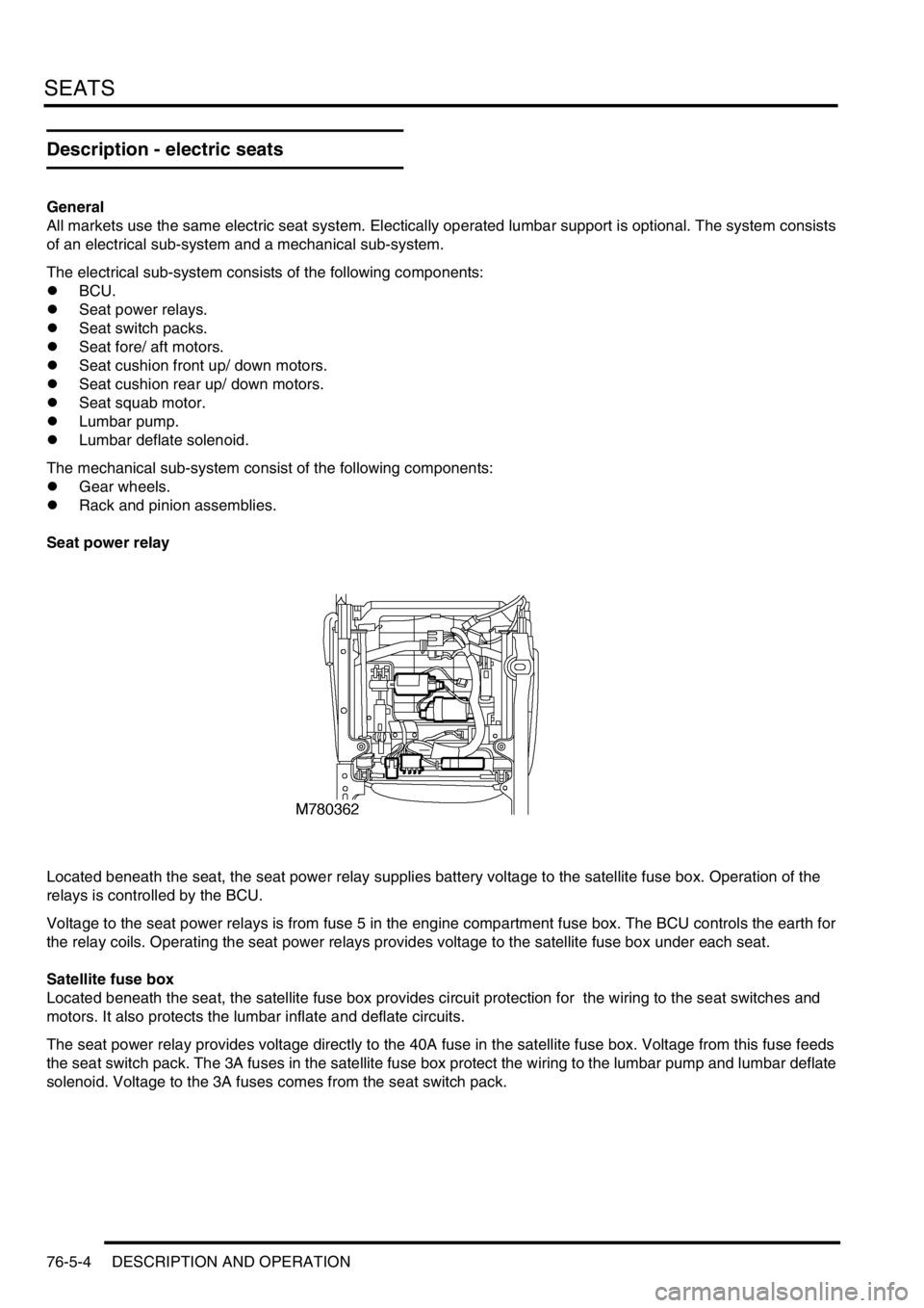
Seat power relay
Located beneath the seat, the seat power relay supplies battery voltage to the satellite fuse box. Operation of the
relays is controlled by the BCU.
Voltage to the seat power relays is from fuse 5 in the engine compartment fuse box. The BCU controls the earth for
the relay coils. Operating the seat power relays provides voltage to the satellite fuse box under each seat.
Satellite fuse box
Located beneath the seat, the satellite fuse box provides circuit protection for the wiring to the seat switches and
motors. It also protects the lumbar inflate and deflate circuits.
The seat power relay provides voltage directly to the 40A fuse in the satellite fuse box. Voltage from this fuse feeds
the seat switch pack. The 3A fuses in the satellite fuse box protect the wiring to the lumbar pump and lumbar deflate
solenoid. Voltage to the 3A fuses comes from the seat switch pack.
Page 1270 of 1672

PANEL REPAIRS
REPAIRS 77-2-21
REPAIRS
Front bulkhead assembly
Remove
1.Disconnect both battery leads, negative lead
first.
2.Disconnect leads/multiplug from alternator.
3.Remove front wing.
+ EXTERIOR FITTINGS, REPAIRS,
Wing - front - up to 03MY.
4.Remove washer reservoir.
+ WIPERS AND WASHERS, REPAIRS,
Reservoir - washer - up to 03MY.
5. Models with A/C: Remove condensor.
+ AIR CONDITIONING, REPAIRS,
Condenser.
6. Diesel models: Remove gearbox fluid cooler.
7.Remove RH and LH headlamps.
+ LIGHTING, REPAIRS, Headlamp - up
to 03MY.
8.Release headlamp levelling motors and
position aside.
9.Release headlamp wiring and position aside.
10.Remove battery.
+ CHARGING AND STARTING,
REPAIRS, Battery.
11.Remove battery tray.
12.Remove air filter assembly.
+ ENGINE MANAGEMENT SYSTEM -
Td5, REPAIRS, Air filter assembly.
+ ENGINE MANAGEMENT SYSTEM -
V8, REPAIRS, Air cleaner assembly.
13.Remove 2 earth leads from LH of front
bulkhead.
14.Remove RH horn.
+ ALARM SYSTEM AND HORN,
REPAIR, Vehicle horn.
15. Models with A/C: Release and remove A/C
pipes.
16.Remove RH and LH crush cans.
17.Remove bonnet release cable.
18.Support bonnet in open position
19.Remove bonnet locking mechanism.
20.Remove VIN plate.
21.Remove 2 bolts securing front bulkhead
assembly to chassis.
22.Remove centre braces.Repair
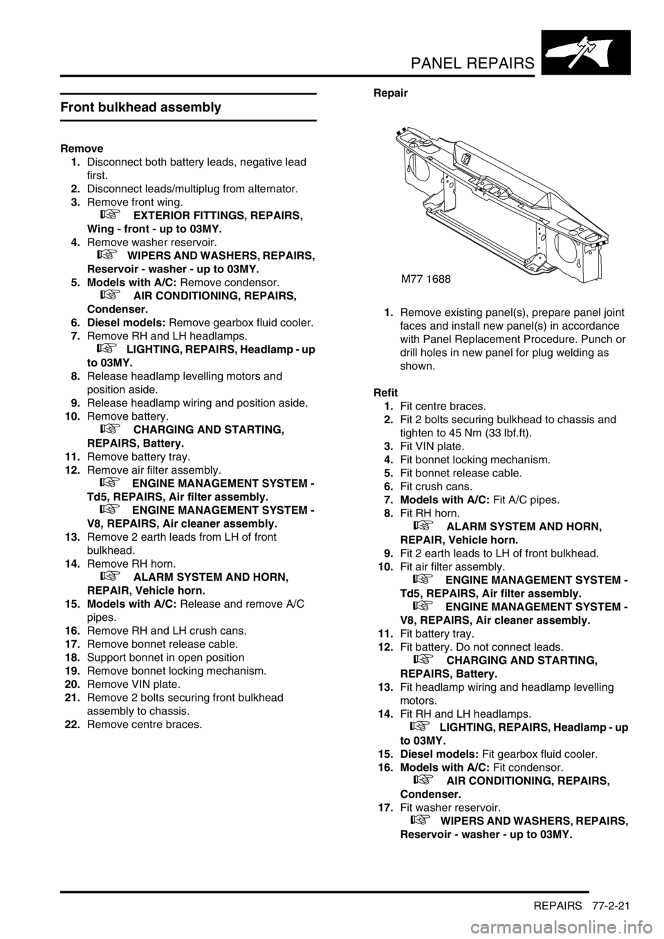
1.Remove existing panel(s), prepare panel joint
faces and install new panel(s) in accordance
with Panel Replacement Procedure. Punch or
drill holes in new panel for plug welding as
shown.
Refit
1.Fit centre braces.
2.Fit 2 bolts securing bulkhead to chassis and
tighten to 45 Nm (33 lbf.ft).
3.Fit VIN plate.
4.Fit bonnet locking mechanism.
5.Fit bonnet release cable.
6.Fit crush cans.
7. Models with A/C: Fit A/C pipes.
8.Fit RH horn.
+ ALARM SYSTEM AND HORN,
REPAIR, Vehicle horn.
9.Fit 2 earth leads to LH of front bulkhead.
10.Fit air filter assembly.
+ ENGINE MANAGEMENT SYSTEM -
Td5, REPAIRS, Air filter assembly.
+ ENGINE MANAGEMENT SYSTEM -
V8, REPAIRS, Air cleaner assembly.
11.Fit battery tray.
12.Fit battery. Do not connect leads.
+ CHARGING AND STARTING,
REPAIRS, Battery.
13.Fit headlamp wiring and headlamp levelling
motors.
14.Fit RH and LH headlamps.
+ LIGHTING, REPAIRS, Headlamp - up
to 03MY.
15. Diesel models: Fit gearbox fluid cooler.
16. Models with A/C: Fit condensor.
+ AIR CONDITIONING, REPAIRS,
Condenser.
17.Fit washer reservoir.
+ WIPERS AND WASHERS, REPAIRS,
Reservoir - washer - up to 03MY.
Page 1271 of 1672

PANEL REPAIRS
77-2-22 REPAIRS
18.Fit front wing.
+ EXTERIOR FITTINGS, REPAIRS,
Wing - front - up to 03MY.
19.Connect leads/multiplug to alternator.
20.Connect battery leads, negative lead last.Bonnet locking platform
Remove
1.Disconnect both battery leads, negative lead
first.
2.Disconnect leads/multiplug from alternator.
3.Remove front bumper assembly.
+ EXTERIOR FITTINGS, REPAIRS,
Bumper assembly - front.
4. Models with A/C: Remove condensor.
+ AIR CONDITIONING, REPAIRS,
Condenser.
5. Diesel models: Remove gearbox fluid cooler.
6.Remove RH and LH headlamps.
+ LIGHTING, REPAIRS, Headlamp - up
to 03MY.
7.Remove RH and LH repeater lamps.
+ LIGHTING, REPAIRS, Lamp - front
repeater.
8.Release headlamp wiring and position aside.
9.Remove battery.
+ CHARGING AND STARTING,
REPAIRS, Battery.
10.Remove battery tray.
11.Remove air filter assembly.
+ ENGINE MANAGEMENT SYSTEM -
Td5, REPAIRS, Air filter assembly.
+ ENGINE MANAGEMENT SYSTEM -
V8, REPAIRS, Air cleaner assembly.
12.Remove RH horn.
+ ALARM SYSTEM AND HORN,
REPAIR, Vehicle horn.
13.Remove bonnet release cable.
14.Support bonnet in open position
15.Remove bonnet locking mechanism.
16.Remove VIN plate.
17.Remove centre braces.
Page 1272 of 1672

PANEL REPAIRS
REPAIRS 77-2-23
Repair
1.Remove existing panel(s), prepare panel joint
faces and install new panel(s) in accordance
with Panel Replacement Procedure. Punch or
drill holes in new panel for plug welding as
shown.
Refit
1.Fit centre braces.
2.Fit VIN plate.
3.Fit bonnet locking mechanism.
4.Fit bonnet release cable.
5.Fit RH horn.
+ ALARM SYSTEM AND HORN,
REPAIR, Vehicle horn.
6.Fit air filter assembly.
+ ENGINE MANAGEMENT SYSTEM -
Td5, REPAIRS, Air filter assembly.
+ ENGINE MANAGEMENT SYSTEM -
V8, REPAIRS, Air cleaner assembly.
7.Fit battery tray.
8.Fit battery. Do not connect leads.
+ CHARGING AND STARTING,
REPAIRS, Battery.
9.Fit headlamp wiring.
10.Fit RH and LH repeater lamps.
+ LIGHTING, REPAIRS, Lamp - front
repeater.
11.Fit RH and LH headlamps.
+ LIGHTING, REPAIRS, Headlamp - up
to 03MY.
12. Diesel models: Fit gearbox fluid cooler.
13. Models with A/C: Fit condensor.
+ AIR CONDITIONING, REPAIRS,
Condenser.
14.Fit bumper assembly.
+ EXTERIOR FITTINGS, REPAIRS,
Bumper assembly - front.
15.Connect leads/multiplug to alternator.
16.Connect battery leads, negative lead last.
Front cross member
Remove
1.Disconnect both battery leads, negative lead
first.
2.Disconnect leads/multiplug from alternator.
3.Remove washer reservoir.
+ WIPERS AND WASHERS, REPAIRS,
Reservoir - washer - up to 03MY.
4. Models with A/C: Remove condensor.
+ AIR CONDITIONING, REPAIRS,
Condenser.
5. Diesel models: Remove gearbox fluid cooler.
6.Remove RH and LH headlamps.
+ LIGHTING, REPAIRS, Headlamp - up
to 03MY.
7.Release headlamp levelling motors and
position aside.
8.Release headlamp wiring and position aside.
9.Remove RH horn.
+ ALARM SYSTEM AND HORN,
REPAIR, Vehicle horn.
10. Models with A/C: Release and remove A/C
pipes.
11.Remove RH and LH crush cans.
12.Remove 2 bolts securing front bulkhead
assembly to chassis.
13.Remove centre braces.
Repair
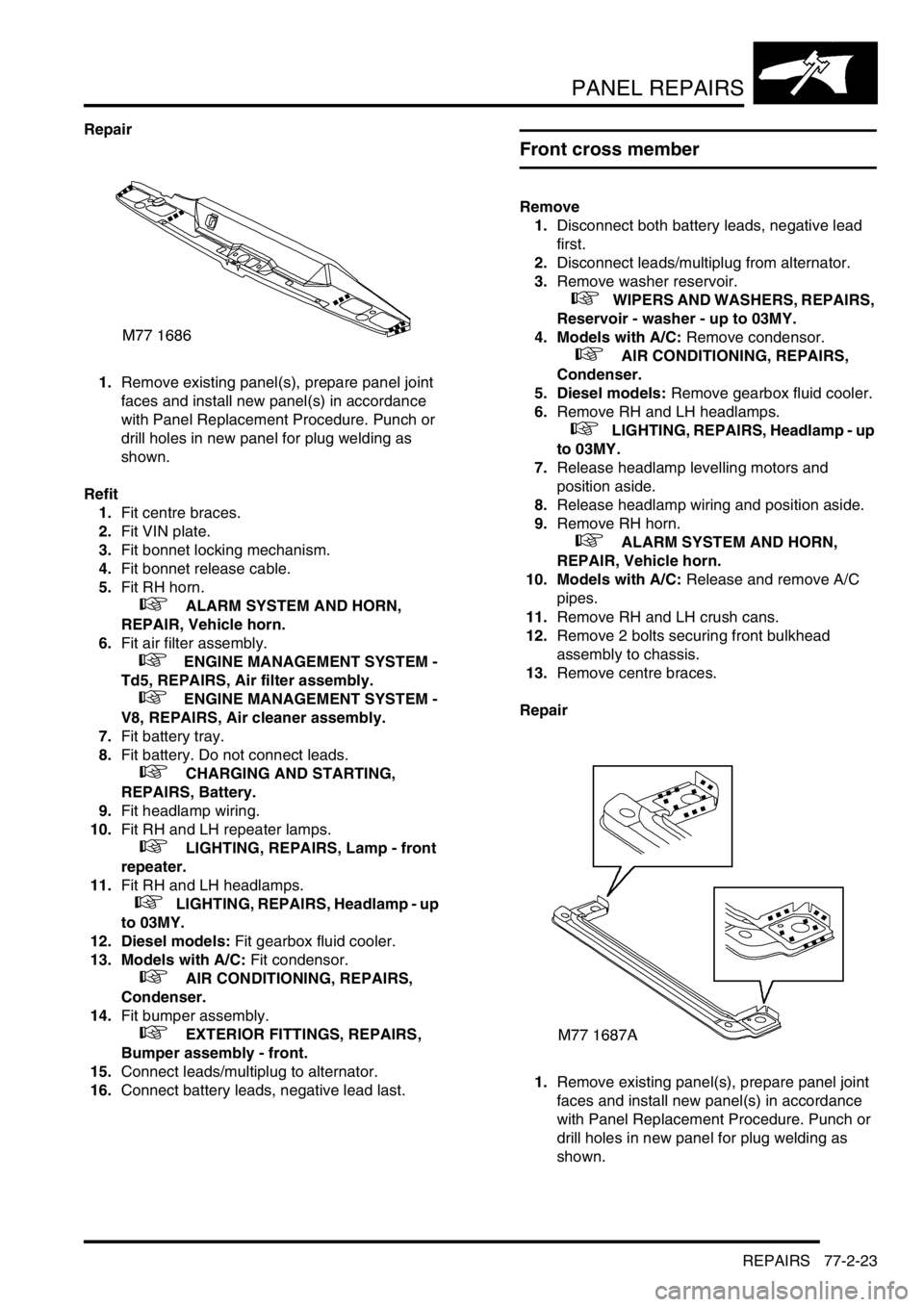
1.Remove existing panel(s), prepare panel joint
faces and install new panel(s) in accordance
with Panel Replacement Procedure. Punch or
drill holes in new panel for plug welding as
shown.