engine LAND ROVER DISCOVERY 2002 Workshop Manual
[x] Cancel search | Manufacturer: LAND ROVER, Model Year: 2002, Model line: DISCOVERY, Model: LAND ROVER DISCOVERY 2002Pages: 1672, PDF Size: 46.1 MB
Page 910 of 1672

STEERING
ADJUSTMENTS 57-23
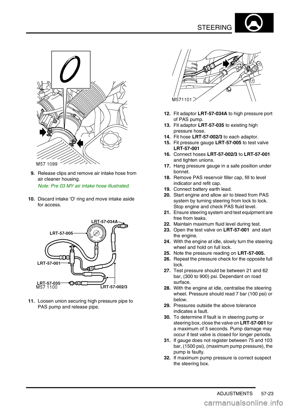
9.Release clips and remove air intake hose from
air cleaner housing.
Note: Pre 03 MY air intake hose illustrated.
10.Discard intake 'O' ring and move intake aside
for access.
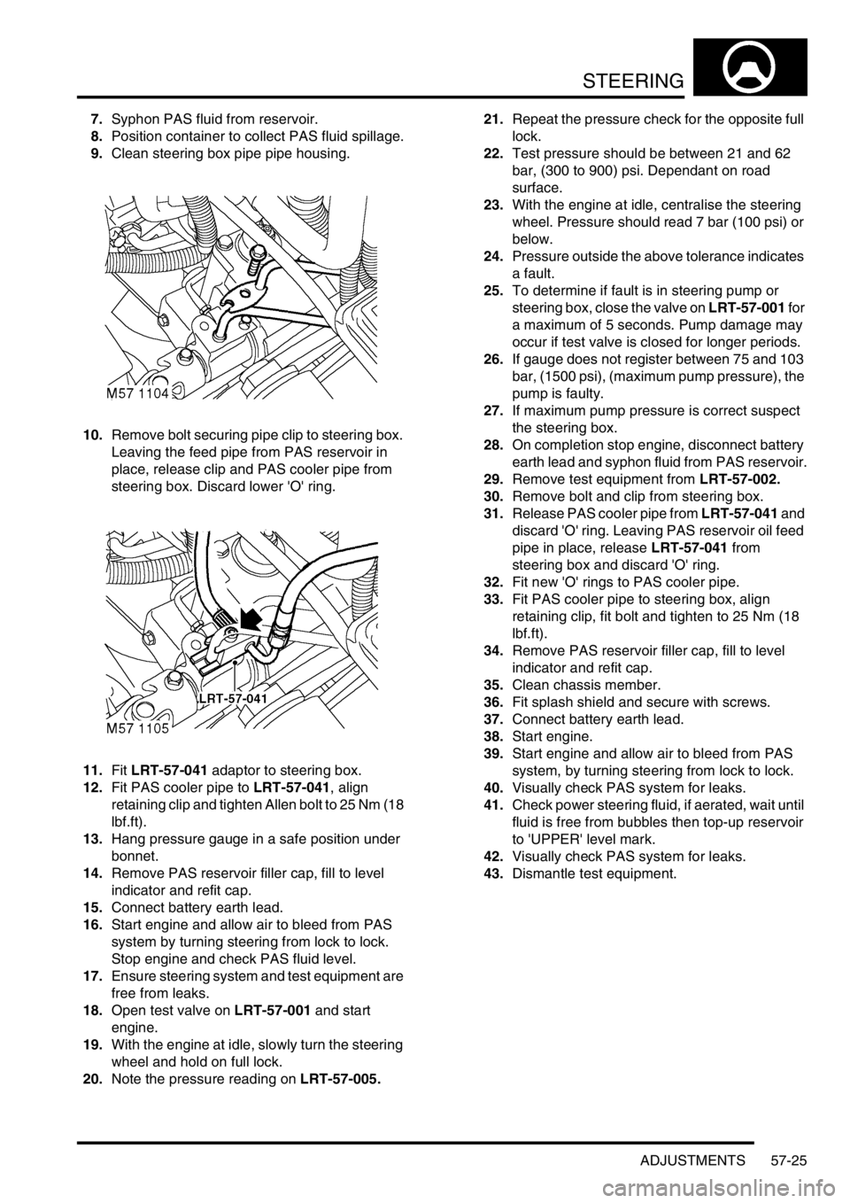
11.Loosen union securing high pressure pipe to
PAS pump and release pipe.12.Fit adaptor LRT-57-034A to high pressure port
of PAS pump.
13.Fit adaptor LRT-57-035 to existing high
pressure hose.
14.Fit hose LRT-57-002/3 to each adaptor.
15.Fit pressure gauge LRT-57-005 to test valve
LRT-57-001
16.Connect hoses LRT-57-002/3 to LRT-57-001
and tighten unions.
17.Hang pressure gauge in a safe position under
bonnet.
18.Remove PAS reservoir filler cap, fill to level
indicator and refit cap.
19.Connect battery earth lead.
20.Start engine and allow air to bleed from PAS
system by turning steering from lock to lock.
Stop engine and check PAS fluid level.
21.Ensure steering system and test equipment are
free from leaks.
22.Maintain maximum fluid level during test.
23.Open the test valve on LRT-57-001 and start
the engine.
24.With the engine at idle, slowly turn the steering
wheel and hold on full lock.
25.Note the pressure reading on LRT-57-005.
26.Repeat the pressure check for the opposite full
lock.
27.Test pressure should be between 21 and 62
bar, (300 to 900) psi. Dependant on road
surface.
28.With the engine at idle, centralise the steering
wheel. Pressure should read 7 bar (100 psi) or
below.
29.Pressures outside the above tolerance
indicates a fault.
30.To determine if fault is in steering pump or
steering box, close the valve on LRT-57-001 for
a maximum of 5 seconds. Pump damage may
occur if test valve is closed for longer periods.
31.If gauge does not register between 75 and 103
bar, (1500 psi), (maximum pump pressure), the
pump is faulty.
32.If maximum pump pressure is correct suspect
the steering box.
Page 911 of 1672

STEERING
57-24 ADJUSTMENTS
33.On completion stop engine, disconnect battery
earth lead and syphon fluid from PAS reservoir.
34.Remove test equipment from LRT-57-002.
35.Clean PAS pump and pipe union.
36.Fit new 'O' ring to high pressure pipe, align to
PAS pump and tighten union to 25 Nm (18
lbf.ft).
37.Secure PAS pipes in clip.
38.Using new 'O' ring fit intake hose to air cleaner
and secure clips.
39.Remove PAS reservoir filler cap, fill to level
indicator and refit cap.
40.Connect battery earth lead.
41.Start engine and allow air to bleed from PAS
system, by turning steering from lock to lock.
42.Visually check PAS system for leaks.
43.Clean chassis member.
44.Check power steering fluid, if aerated, wait until
fluid is free from bubbles then top-up reservoir
to 'UPPER' level mark.
45.Lower vehicle.
46.Dismantle test equipment.
Power steering pressure check - V8 RHD
models
$% 57.90.10.01
Check
1.Fit gauge and hose LRT-57-005 to valve
assembly LRT-57-001, tighten union.
2.Fit 2 hoses LRT-57-002 to valve assembly
LRT-57-001 and tighten unions.
3.Fit adaptor hoses LRT-57-041 to LRT-57-002
and tighten unions.
4.Disconnect battery earth lead.
5.Remove 5 screws securing front splash shield
to chassis. Remove shield.
6.Clean PAS fluid reservoir around filler cap and
fluid level indicators.
Page 912 of 1672

STEERING
ADJUSTMENTS 57-25
7.Syphon PAS fluid from reservoir.
8.Position container to collect PAS fluid spillage.
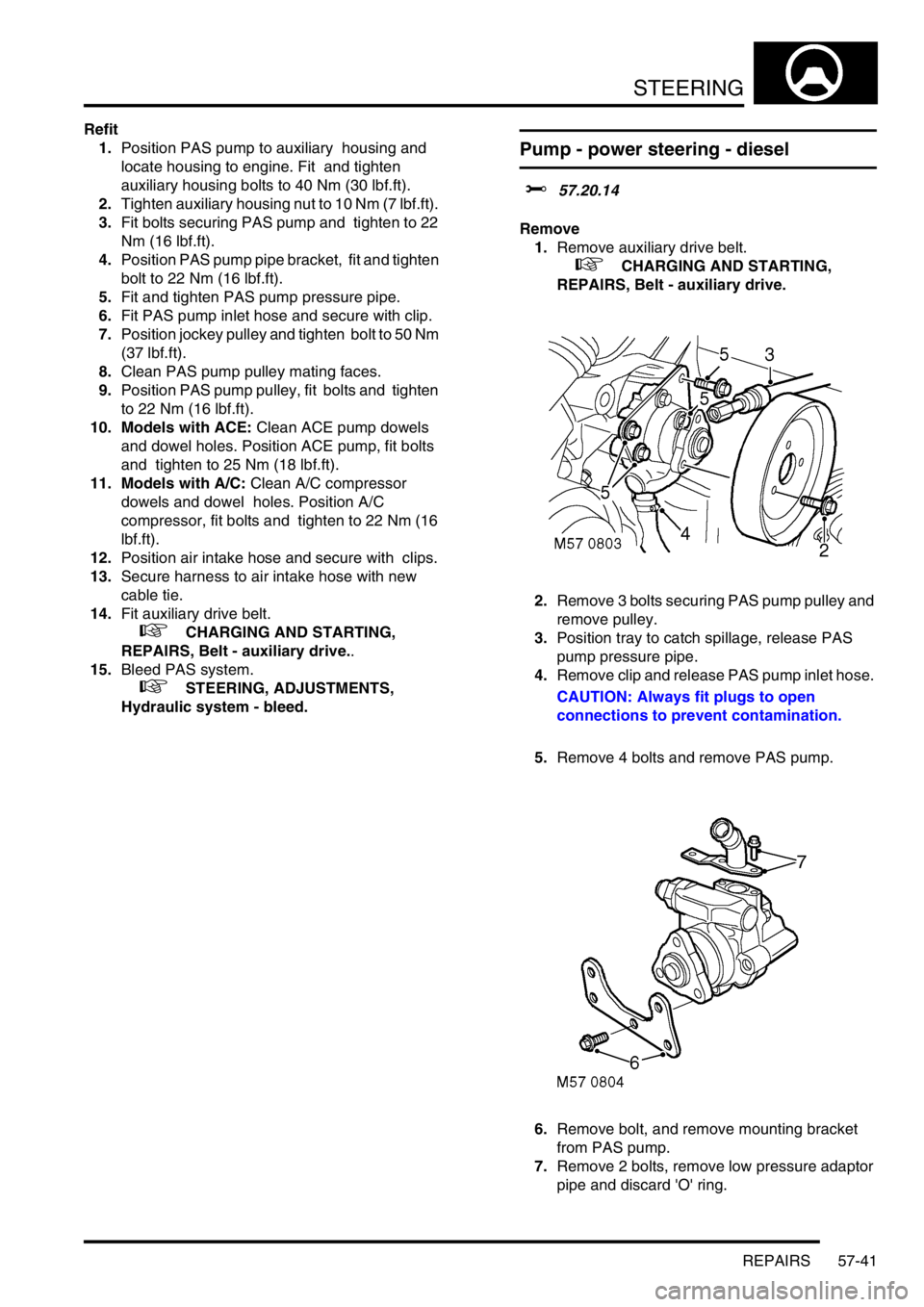
9.Clean steering box pipe pipe housing.
10.Remove bolt securing pipe clip to steering box.
Leaving the feed pipe from PAS reservoir in
place, release clip and PAS cooler pipe from
steering box. Discard lower 'O' ring.
11.Fit LRT-57-041 adaptor to steering box.
12.Fit PAS cooler pipe to LRT-57-041, align
retaining clip and tighten Allen bolt to 25 Nm (18
lbf.ft).
13.Hang pressure gauge in a safe position under
bonnet.
14.Remove PAS reservoir filler cap, fill to level
indicator and refit cap.
15.Connect battery earth lead.
16.Start engine and allow air to bleed from PAS
system by turning steering from lock to lock.
Stop engine and check PAS fluid level.
17.Ensure steering system and test equipment are
free from leaks.
18.Open test valve on LRT-57-001 and start
engine.
19.With the engine at idle, slowly turn the steering
wheel and hold on full lock.
20.Note the pressure reading on LRT-57-005.21.Repeat the pressure check for the opposite full
lock.
22.Test pressure should be between 21 and 62
bar, (300 to 900) psi. Dependant on road
surface.
23.With the engine at idle, centralise the steering
wheel. Pressure should read 7 bar (100 psi) or
below.
24.Pressure outside the above tolerance indicates
a fault.
25.To determine if fault is in steering pump or
steering box, close the valve on LRT-57-001 for
a maximum of 5 seconds. Pump damage may
occur if test valve is closed for longer periods.
26.If gauge does not register between 75 and 103
bar, (1500 psi), (maximum pump pressure), the
pump is faulty.
27.If maximum pump pressure is correct suspect
the steering box.
28.On completion stop engine, disconnect battery
earth lead and syphon fluid from PAS reservoir.
29.Remove test equipment from LRT-57-002.
30.Remove bolt and clip from steering box.
31.Release PAS cooler pipe from LRT-57-041 and
discard 'O' ring. Leaving PAS reservoir oil feed
pipe in place, release LRT-57-041 from
steering box and discard 'O' ring.
32.Fit new 'O' rings to PAS cooler pipe.
33.Fit PAS cooler pipe to steering box, align
retaining clip, fit bolt and tighten to 25 Nm (18
lbf.ft).
34.Remove PAS reservoir filler cap, fill to level
indicator and refit cap.
35.Clean chassis member.
36.Fit splash shield and secure with screws.
37.Connect battery earth lead.
38.Start engine.
39.Start engine and allow air to bleed from PAS
system, by turning steering from lock to lock.
40.Visually check PAS system for leaks.
41.Check power steering fluid, if aerated, wait until
fluid is free from bubbles then top-up reservoir
to 'UPPER' level mark.
42.Visually check PAS system for leaks.
43.Dismantle test equipment.
Page 916 of 1672

STEERING
REPAIRS 57-29
12. RH drive models with ACE: Position ACE
control arms to access steering box bolts.
13.With assistance remove 4 securing bolts and
remove steering box.
14.Remove centralising bolt from steering box. Refit
1.Fit centralising bolt to steering box.
2. With assistance, position steering box, fit bolts
and tighten to 90 Nm (66 lbf.ft).
3. RH drive models with ACE: Ensure washer is
in place on lower ball joint of anti-roll bar link,
then connect lower ball joint to axle. Tighten nut
to 100 Nm (74 lbf.ft).
4.Position drag link, fit nut and tighten to 80 Nm
(59 lbf.ft).
5.Position Panhard rod, fit bolt and nut and
tighten to 230 Nm (170 lbf.ft).
6.Clean PAS pipe ends and 'O' ring recess.
7.Lubricate new 'O' rings for PAS pipes with clean
PAS fluid.
8.Fit 'O' rings to PAS pipes and position pipes in
steering box. Fit PAS pipe bracket and tighten
bolt to 22 Nm (16 lbf.ft).
9. RHD models: Fit oil filter and housing:
lClean oil filter housing and engine mating
faces.
lLubricate new 'O' ring with clean engine oil
and fit to housing.
lPosition oil filter housing and tighten bolts to
9 Nm (7 lbf.ft).
10.Ensure steering wheel is centralised. Fit
universal joint between steering box and
intermediate shaft and tighten bolts to 25 Nm
(18 lbf.ft).
11.Remove centralising bolt from steering box.
12.Fit road wheel(s) and tighten nuts to 140 Nm
(103 lbf.ft)..
13.Remove stand(s) and lower vehicle.
14.Check and top up engine oil.
15.Bleed PAS system.
+ STEERING, ADJUSTMENTS,
Hydraulic system - bleed.
16.Centralise steering linkage
+ STEERING, ADJUSTMENTS,
Steering linkage - centralise.
Page 919 of 1672

STEERING
57-32 REPAIRS
17.Remove securing nut and bolt and release
Panhard rod.
18.Remove nut securing drag link to drop arm.
Using LRT-57-036, break taper joint and
release drag link. 19. Models with ACE: Remove nut securing anti-
roll bar link lower ball joint and release joint.
20.With assistance, remove 2 nuts and bolts
securing LH engine mounting to chassis.
Page 920 of 1672

STEERING
REPAIRS 57-33
21.With assistance remove 2 nuts and bolts
securing RH engine mounting to chassis.
22.Support the engine weight on a jack.
CAUTION: To prevent damage to
components, cushion the jack pad with a
block of wood or hard rubber.
23.Raise the engine sufficiently to allow the
steering box to clear the sump.
24. Models with ACE: Position ACE control arms
to access steering box bolts. 25.With assistance remove 4 bolts securing
steering box and remove steering box.
26.Remove centralising bolt from steering box.
Refit
1.Fit centralising bolt to steering box.
2.With assistance, position steering box, fit bolts
and tighten to 90 Nm (66 lbf.ft).
3.Lower the engine onto its mountings. Fit engine
mounting bolts and tighten to 85 Nm (63 lbf.ft).
4. Models with ACE: Ensure washer is in place
on lower ball joint of anti-roll bar link, then
connect lower ball joint to axle. Tighten nut to
100 Nm (74 lbf.ft).
5.Position drag link, fit nut and tighten to 80 Nm
(59 lbf.ft).
6.Position Panhard rod, fit bolt and nut and
tighten to 230 Nm (170 lbf.ft).
7.Position coolant rail and secure with clips and
bolt.
8.Fit coolant hoses and secure with clips.
9. Models with ACE: Fit and tighten bolt
securing ACE pipes to chassis.
10.Clean PAS pipe ends and 'O' ring recess.
11.Lubricate new 'O' rings for PAS pipes with clean
PAS fluid.
12.Fit 'O' rings to PAS pipes and position pipes in
steering box. Fit PAS pipe bracket and tighten
bolt to 22 Nm (16 lbf.ft).
13.Ensure steering wheel is centralised. Fit
universal joint between steering box and
intermediate shaft and tighten bolts to 25 Nm
(18 lbf.ft).
14.Remove centralising bolt from steering box.
15.Fit intercooler to turbo hose and secure with
clips.
16.Fit road wheel(s) and tighten nuts to 140 Nm
(103 lbf.ft).
17.Remove stand(s) and lower vehicle.
18.Connect battery earth lead.
19.Fit battery cover.
20.Refill cooling system.
+ COOLING SYSTEM - Td5,
ADJUSTMENTS, Drain and refill.
21.Bleed PAS system.
+ STEERING, ADJUSTMENTS,
Hydraulic system - bleed.
22.Centralise steering linkage
+ STEERING, ADJUSTMENTS,
Steering linkage - centralise.
Page 928 of 1672

STEERING
REPAIRS 57-41
Refit
1.Position PAS pump to auxiliary housing and
locate housing to engine. Fit and tighten
auxiliary housing bolts to 40 Nm (30 lbf.ft).
2.Tighten auxiliary housing nut to 10 Nm (7 lbf.ft).
3.Fit bolts securing PAS pump and tighten to 22
Nm (16 lbf.ft).
4.Position PAS pump pipe bracket, fit and tighten
bolt to 22 Nm (16 lbf.ft).
5.Fit and tighten PAS pump pressure pipe.
6.Fit PAS pump inlet hose and secure with clip.
7.Position jockey pulley and tighten bolt to 50 Nm
(37 lbf.ft).
8.Clean PAS pump pulley mating faces.
9.Position PAS pump pulley, fit bolts and tighten
to 22 Nm (16 lbf.ft).
10. Models with ACE: Clean ACE pump dowels
and dowel holes. Position ACE pump, fit bolts
and tighten to 25 Nm (18 lbf.ft).
11. Models with A/C: Clean A/C compressor
dowels and dowel holes. Position A/C
compressor, fit bolts and tighten to 22 Nm (16
lbf.ft).
12.Position air intake hose and secure with clips.
13.Secure harness to air intake hose with new
cable tie.
14.Fit auxiliary drive belt.
+ CHARGING AND STARTING,
REPAIRS, Belt - auxiliary drive..
15.Bleed PAS system.
+ STEERING, ADJUSTMENTS,
Hydraulic system - bleed.
Pump - power steering - diesel
$% 57.20.14
Remove
1.Remove auxiliary drive belt.
+ CHARGING AND STARTING,
REPAIRS, Belt - auxiliary drive.
2.Remove 3 bolts securing PAS pump pulley and
remove pulley.
3.Position tray to catch spillage, release PAS
pump pressure pipe.
4.Remove clip and release PAS pump inlet hose.
CAUTION: Always fit plugs to open
connections to prevent contamination.
5.Remove 4 bolts and remove PAS pump.
6.Remove bolt, and remove mounting bracket
from PAS pump.
7.Remove 2 bolts, remove low pressure adaptor
pipe and discard 'O' ring.
Page 944 of 1672

FRONT SUSPENSION
DESCRIPTION AND OPERATION 60-5
Coil springs
Coil springs are fitted to the front axle of the vehicle. The front springs differ between petrol and Diesel variants. Each
spring is retained at its base by the lower spring seat. The top of each spring is located in the upper spring seat
isolator. The upper spring seat is manufactured from natural rubber , with a bonded metal plate and four bonded studs
which provide for the attachment of the damper turret. The rubber isolator reduces noise transmitted to the chassis
and body from the suspension.
The coil springs must be installed correctly. The bottom coil of the spring locates in a recess in the lower spring seat.
The top coil of the spring is ground flat to locate the upper spring seat isolator.
Coil Spring Specifications – Models up to 03 Model Year
The front springs on petrol variants are manufactured from carbon chrome 13.9 mm (0.55 in) diameter bar. The spring
has 7.6 coils and a free length of 377 mm (14.8 in). The petrol front spring is identified by a pink and orange stripe
painted on a number of coils.
The front springs on Diesel variants are manufactured from carbon chrome 13.9 mm (0.55 in) diameter bar. The spring
has 7.6 coils and a free length of 383 mm (15.0 in). The Diesel front spring is identified by a white and purple stripe
painted on a number of coils.
Coil Spring Specifications – Models from 03 Model Year
The introduction of the 03MY vehicle introduced a range of additional spring fitments. These were introduced to cover
the introduction of the 4.6l V8 engine, the fitment of a front mounted winch and to optimise the vehicle trim heights.
The coil springs are manufactured from silicon manganese 13.8 mm or 13.9 mm (0.54 in or 0.55 in) diameter bar. The
following spring data table shows the colour codes, number of coils and spring free length.
Page 949 of 1672

FRONT SUSPENSION
60-10 DESCRIPTION AND OPERATION
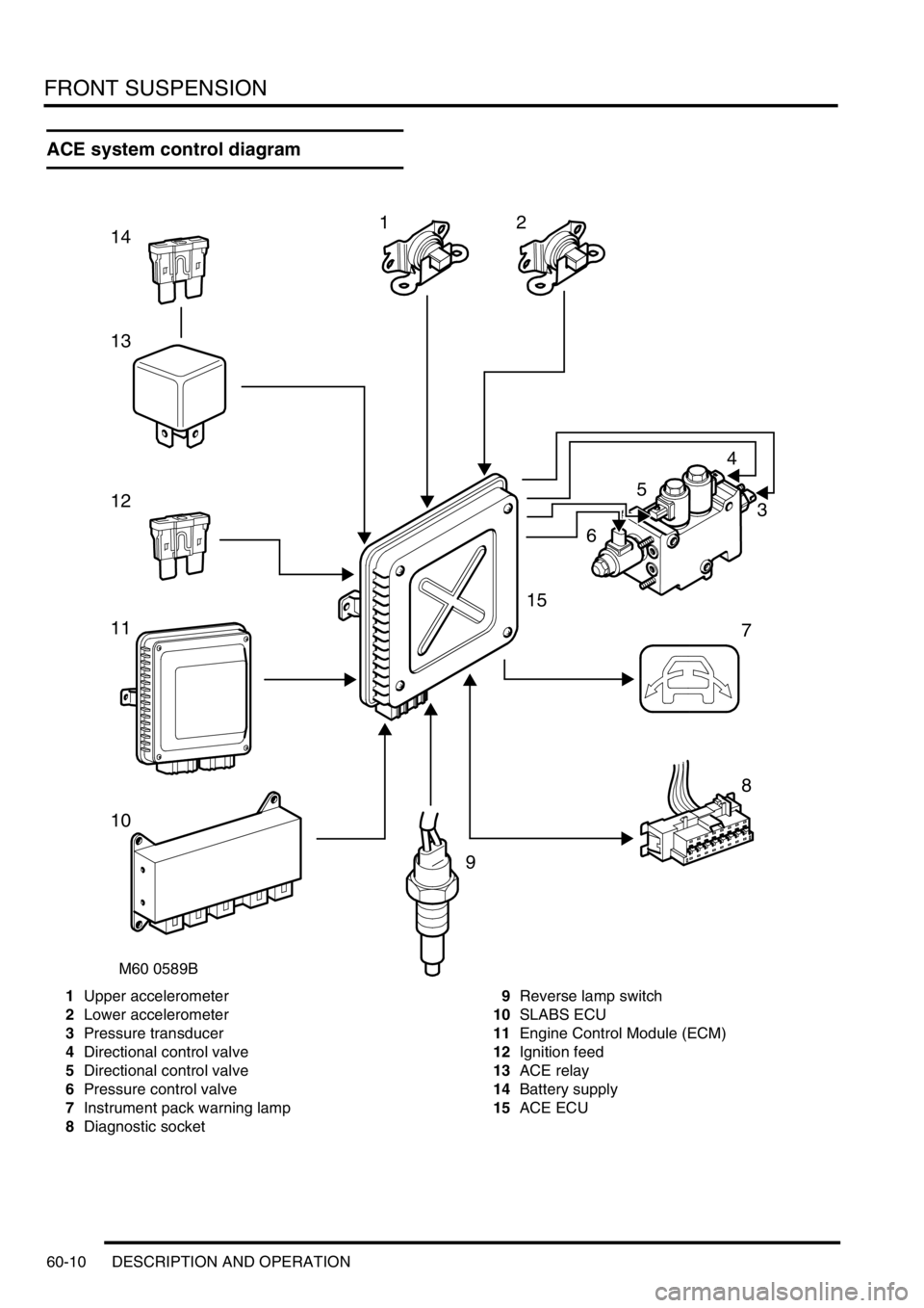
ACE system control diagram
1Upper accelerometer
2Lower accelerometer
3Pressure transducer
4Directional control valve
5Directional control valve
6Pressure control valve
7Instrument pack warning lamp
8Diagnostic socket9Reverse lamp switch
10SLABS ECU
11Engine Control Module (ECM)
12Ignition feed
13ACE relay
14Battery supply
15ACE ECU
M60 0589B
12
5
4
3
6
7
8
9
10
11
12
13
14
15
Page 952 of 1672

FRONT SUSPENSION
DESCRIPTION AND OPERATION 60-13
Lateral acceleration of the body is sensed by two accelerometers and signals are transmitted to the ECU. The engine
driven hydraulic pump supplies a constant hydraulic flow to the valve block. Two directional control valves are
solenoid operated by the ECU and these supply fluid to the applicable side of each actuator to apply an equal and
opposite force to the torsion bar. In operation the ACE system maintains the attitude of the vehicle body when
cornering.
The ACE system uses a semi-synthetic hydraulic fluid which is the same as the fluid used for the PAS system. The
total capacity of the ACE system is 1.62 litres (0.42 US Gallons).
CAUTION: The ACE hydraulic system is extremely sensitive to the ingress of dirt or debris. The smallest
amount could render the system unserviceable. It is imperative that the following precautions are taken.
lACE components are thoroughly cleaned externally before work commences;
lall opened pipe and module ports are capped immediately;
lall fluid is stored in and administered through clean containers.
In the event of an ECU or hydraulic failure the system will fail safe to a 'locked bars' condition. The 'locked bars'
condition will allow the torsion bars to operate in a similar manner as conventional 'passive' anti-roll bars. Prolonged
cornering forces will allow a progressive increase in roll angle due to hydraulic leakage through the actuators and
valve block. Failures will be relayed to the driver by the illumination of the ACE warning lamp in the instrument pack.
Faults are recorded by the ECU and can be retrieved using TestBook.
When the ignition switch is moved to position II, the warning lamp will illuminate for two seconds to check functionality.
The warning lamp functionality can also be checked using TestBook.
TestBook must also be used to perform a bleeding procedure after maintenance operations have been performed to
ensure that complete system bleeding is performed. Trapped air in the system can seriously reduce the system
performance.
Fluid reservoir
The moulded plastic fluid reservoir is mounted on the left hand side of the engine compartment on a bracket which is
attached to the inner wing. The reservoir is dual purpose, being divided into two separate chambers; one for the ACE
system and one for the PAS system. Each chamber has its own filler neck and cap and is identified by moulded
lettering on the reservoir adjacent to each filler.
A non-serviceable filter assembly is fitted in the base of each chamber. The filter is made from fine stainless steel
mesh which is moulded into the body of the reservoir. The filter removes particulate matter from the fluid before it is
drawn into the hydraulic pump.
Upper and lower fluid level marks are moulded onto the reservoir body. The capacity of the ACE reservoir chamber
to the upper level mark is 0.5 litre (0.13 US Gallon).