differential LAND ROVER DISCOVERY 2002 Repair Manual
[x] Cancel search | Manufacturer: LAND ROVER, Model Year: 2002, Model line: DISCOVERY, Model: LAND ROVER DISCOVERY 2002Pages: 1672, PDF Size: 46.1 MB
Page 824 of 1672
AUTOMATIC GEARBOX - ZF4HP22 - 24
REPAIRS 44-27
11.Drain transfer gearbox oil.
+ MAINTENANCE, PROCEDURES,
Transfer box.
12.Remove front propeller shaft
+ PROPELLER SHAFTS, REPAIRS,
Propeller shaft - front.
13.Remove rear propeller shaft
+ PROPELLER SHAFTS, REPAIRS,
Propeller shaft - rear.
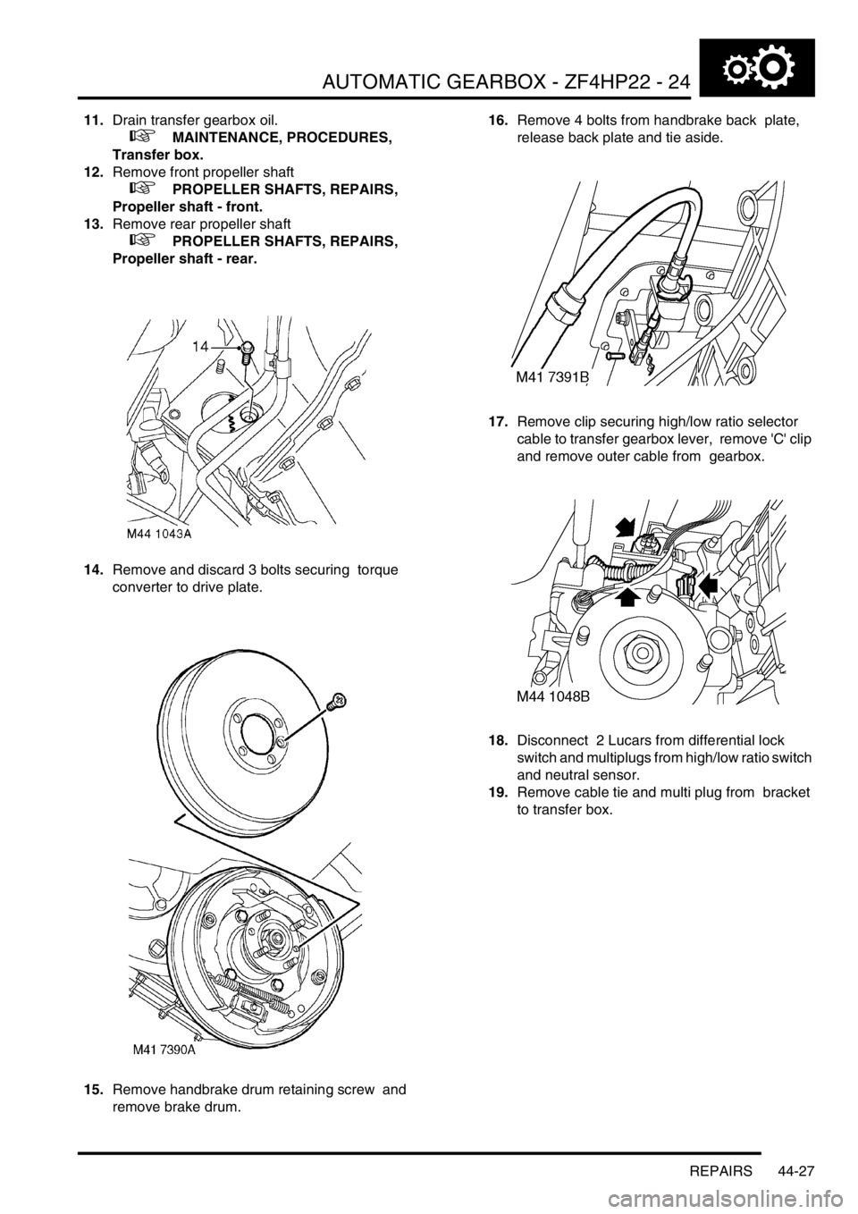
14.Remove and discard 3 bolts securing torque
converter to drive plate.
15.Remove handbrake drum retaining screw and
remove brake drum. 16.Remove 4 bolts from handbrake back plate,
release back plate and tie aside.
17.Remove clip securing high/low ratio selector
cable to transfer gearbox lever, remove 'C' clip
and remove outer cable from gearbox.
18.Disconnect 2 Lucars from differential lock
switch and multiplugs from high/low ratio switch
and neutral sensor.
19.Remove cable tie and multi plug from bracket
to transfer box.
Page 827 of 1672
AUTOMATIC GEARBOX - ZF4HP22 - 24
44-30 REPAIRS
14.Secure gearbox breather pipes to bulkhead
clip.
15.Connect multiplugs to high/low ratio switch and
neutral sensor. Connect Lucars to differential
lock switch.
16.Position cable tie and multi plug to transfer box
bracket.
17.Connect high/low ratio cable to transfer box
and secure with retaining clips.
18.Position hand brake back plate and tighten
bolts to 75 Nm (55 lbf.ft).
19.Fit hand brake drum and tighten screw.
20.Remove bolts securing tool LRT-99-008A to
gearbox.
21.Rotate engine to align torque converter, fit new
bolts and tighten to 50 Nm (37 lbf.ft).
22.Fit rear propeller shaft.
+ PROPELLER SHAFTS, REPAIRS,
Propeller shaft - rear.
23.Fit front propeller shaft.
+ PROPELLER SHAFTS, REPAIRS,
Propeller shaft - front.
24.Fill transfer gearbox with oil.
+ MAINTENANCE, PROCEDURES,
Transfer box.
25.Fill automatic gearbox with oil.
+ MAINTENANCE, PROCEDURES,
Automatic gearbox.
26.Position intermediate silencer and secure to
mounting rubbers.
27.Clean silencer and tail pipe mating faces.
28.Position new gasket to tail pipe and tighten
nuts to 25 Nm (18 lbf.ft).
29.Fit exhaust front pipe.
+ MANIFOLDS AND EXHAUST
SYSTEMS - Td5, REPAIRS, Pipe - front.
30.Fit bolt securing closing plate to gearbox
housing and tighten to 7 Nm (5.2 lbf.ft).
31.Fit upper bolts securing gearbox housing to
engine and tighten to 50 Nm (37 lbf.ft).
32.Fit starter motor.
+ CHARGING AND STARTING,
REPAIRS, Starter motor - diesel.
33.Tighten remaining gearbox housing to engine
bolts to 50 Nm (37 lbf.ft).
34.Connect battery earth lead.
35.Fit battery cover and secure with fixings.
36.Check and adjust selector cable.
+ AUTOMATIC GEARBOX - ZF4HP22
- 24, ADJUSTMENTS, Cable - selector.
Gearbox - convertor and transfer
gearbox - V8
$% 44.20.04.99
Remove
1.Release fixings and remove battery cover.
2.Disconnect battery earth lead.
3.Raise vehicle on a ramp.
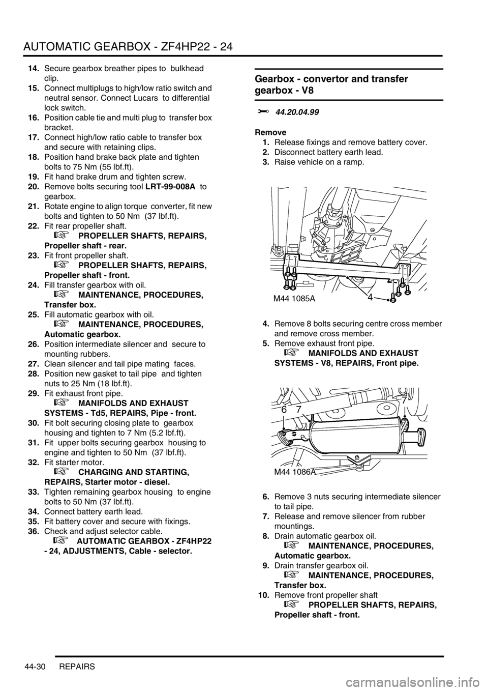
4.Remove 8 bolts securing centre cross member
and remove cross member.
5.Remove exhaust front pipe.
+ MANIFOLDS AND EXHAUST
SYSTEMS - V8, REPAIRS, Front pipe.
6.Remove 3 nuts securing intermediate silencer
to tail pipe.
7.Release and remove silencer from rubber
mountings.
8.Drain automatic gearbox oil.
+ MAINTENANCE, PROCEDURES,
Automatic gearbox.
9.Drain transfer gearbox oil.
+ MAINTENANCE, PROCEDURES,
Transfer box.
10.Remove front propeller shaft
+ PROPELLER SHAFTS, REPAIRS,
Propeller shaft - front.
Page 828 of 1672
AUTOMATIC GEARBOX - ZF4HP22 - 24
REPAIRS 44-31
11.Remove rear propeller shaft
+ PROPELLER SHAFTS, REPAIRS,
Propeller shaft - rear.
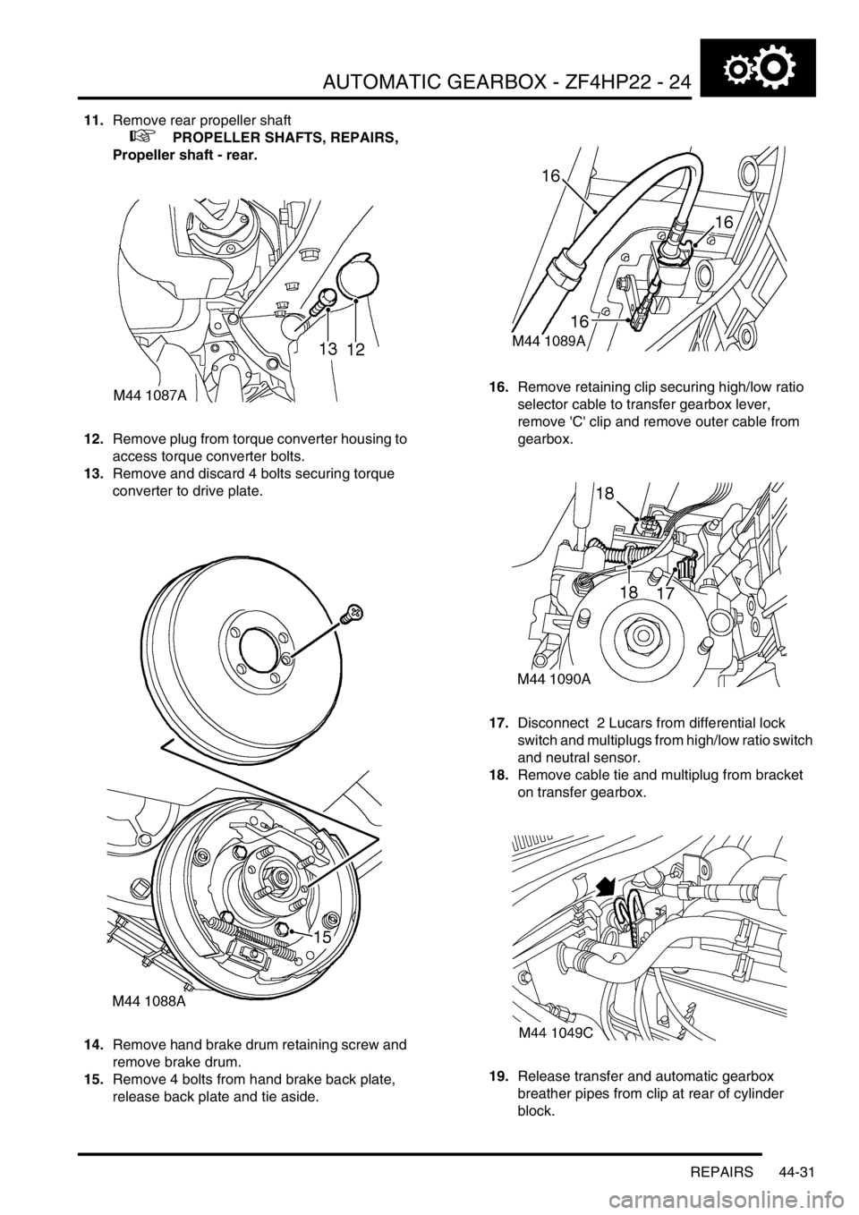
12.Remove plug from torque converter housing to
access torque converter bolts.
13.Remove and discard 4 bolts securing torque
converter to drive plate.
14.Remove hand brake drum retaining screw and
remove brake drum.
15.Remove 4 bolts from hand brake back plate,
release back plate and tie aside. 16.Remove retaining clip securing high/low ratio
selector cable to transfer gearbox lever,
remove 'C' clip and remove outer cable from
gearbox.
17.Disconnect 2 Lucars from differential lock
switch and multiplugs from high/low ratio switch
and neutral sensor.
18.Remove cable tie and multiplug from bracket
on transfer gearbox.
19.Release transfer and automatic gearbox
breather pipes from clip at rear of cylinder
block.
Page 830 of 1672
AUTOMATIC GEARBOX - ZF4HP22 - 24
REPAIRS 44-33
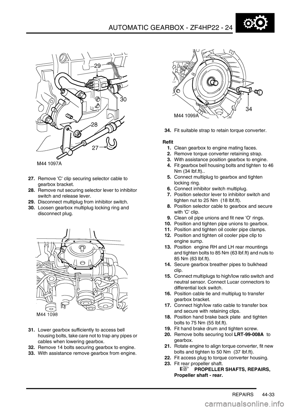
27.Remove 'C' clip securing selector cable to
gearbox bracket.
28.Remove nut securing selector lever to inhibitor
switch and release lever.
29.Disconnect multiplug from inhibitor switch.
30.Loosen gearbox multiplug locking ring and
disconnect plug.
31.Lower gearbox sufficiently to access bell
housing bolts, take care not to trap any pipes or
cables when lowering gearbox.
32.Remove 14 bolts securing gearbox to engine.
33.With assistance remove gearbox from engine.34.Fit suitable strap to retain torque converter.
Refit
1.Clean gearbox to engine mating faces.
2.Remove torque converter retaining strap.
3.With assistance position gearbox to engine.
4.Fit gearbox bell housing bolts and tighten to 46
Nm (34 lbf.ft)..
5.Connect multiplug to gearbox and tighten
locking ring.
6.Connect inhibitor switch multiplug.
7.Position selector lever to inhibitor switch and
tighten nut to 25 Nm (18 lbf.ft).
8.Position selector cable to gearbox and secure
with 'C' clip.
9.Clean oil pipe unions and fit new 'O' rings.
10.Position and tighten pipe unions to gearbox.
11.Position and tighten oil cooler pipe clamps.
12.Position and tighten oil cooler pipe clip to
engine sump.
13.Position engine RH and LH rear mountings
and tighten bolts to 85 Nm (63 lbf.ft) and nuts to
85 Nm (63 lbf.ft).
14.Secure gearbox breather pipes to bulkhead
clip.
15.Connect multiplugs to high/low ratio switch and
neutral sensor. Connect Lucar connectors to
differential lock switch.
16.Position cable tie and multiplug to transfer
gearbox bracket.
17.Connect high/low ratio cable to transfer box
and secure with retaining clips.
18.Position hand brake back plate and tighten
bolts to 75 Nm (55 lbf.ft).
19.Fit hand brake drum and tighten screw.
20.Remove bolts securing tool LRT-99-008A to
gearbox.
21.Rotate engine to align torque converter, fit new
bolts and tighten to 50 Nm (37 lbf.ft).
22.Fit access plug to torque converter housing.
23.Fit rear propeller shaft.
+ PROPELLER SHAFTS, REPAIRS,
Propeller shaft - rear.
Page 853 of 1672
PROPELLER SHAFTS
47-2 DESCRIPTION AND OPERATION
Description
General
Front and rear propeller shafts transmit the drive from the transfer box to the axles.
On vehicles from 03 model year fitted with the 4.6l V8 engine and 4HP24 transmission, the front propeller shaft is 15
mm (0.6 in) longer and the rear propeller shaft is 15mm (0.6 in) shorter than those used on vehicles with the 4.0l V8
and Td5 engines. This is to accomodate an increase in length of the 4HP24 transmission.
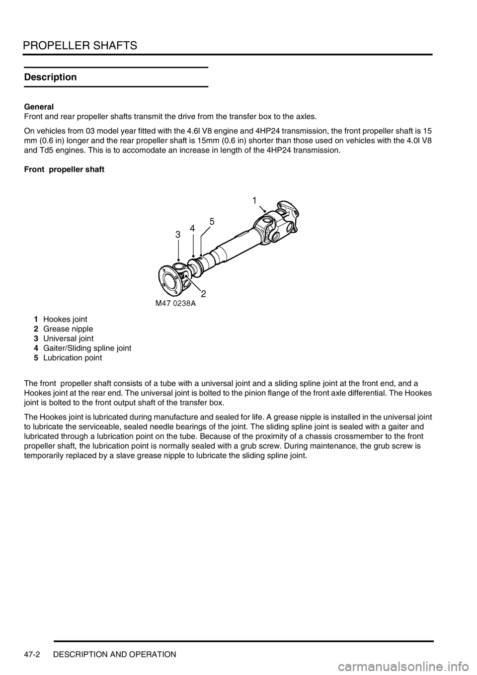
Front propeller shaft
1Hookes joint
2Grease nipple
3Universal joint
4Gaiter/Sliding spline joint
5Lubrication point
The front propeller shaft consists of a tube with a universal joint and a sliding spline joint at the front end, and a
Hookes joint at the rear end. The universal joint is bolted to the pinion flange of the front axle differential. The Hookes
joint is bolted to the front output shaft of the transfer box.
The Hookes joint is lubricated during manufacture and sealed for life. A grease nipple is installed in the universal joint
to lubricate the serviceable, sealed needle bearings of the joint. The sliding spline joint is sealed with a gaiter and
lubricated through a lubrication point on the tube. Because of the proximity of a chassis crossmember to the front
propeller shaft, the lubrication point is normally sealed with a grub screw. During maintenance, the grub screw is
temporarily replaced by a slave grease nipple to lubricate the sliding spline joint.
Page 854 of 1672
PROPELLER SHAFTS
DESCRIPTION AND OPERATION 47-3
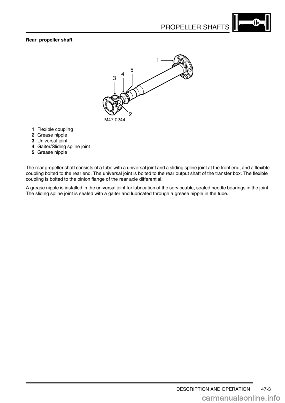
Rear propeller shaft
1Flexible coupling
2Grease nipple
3Universal joint
4Gaiter/Sliding spline joint
5Grease nipple
The rear propeller shaft consists of a tube with a universal joint and a sliding spline joint at the front end, and a flexible
coupling bolted to the rear end. The universal joint is bolted to the rear output shaft of the transfer box. The flexible
coupling is bolted to the pinion flange of the rear axle differential.
A grease nipple is installed in the universal joint for lubrication of the serviceable, sealed needle bearings in the joint.
The sliding spline joint is sealed with a gaiter and lubricated through a grease nipple in the tube.
Page 856 of 1672
PROPELLER SHAFTS
REPAIRS 47-5
REPAIRS
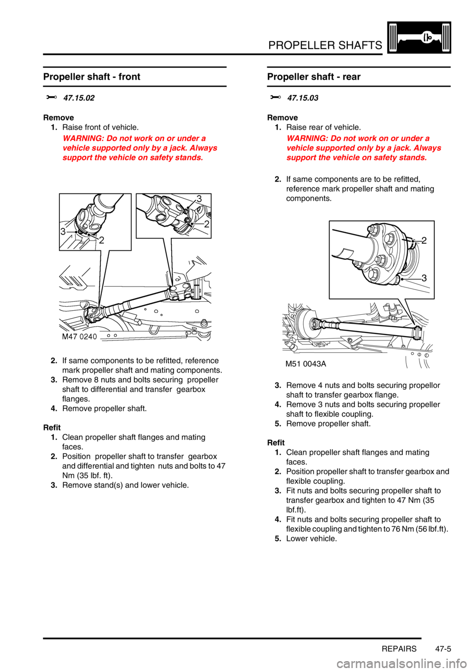
Propeller shaft - front
$% 47.15.02
Remove
1.Raise front of vehicle.
WARNING: Do not work on or under a
vehicle supported only by a jack. Always
support the vehicle on safety stands.
2.If same components to be refitted, reference
mark propeller shaft and mating components.
3.Remove 8 nuts and bolts securing propeller
shaft to differential and transfer gearbox
flanges.
4.Remove propeller shaft.
Refit
1.Clean propeller shaft flanges and mating
faces.
2.Position propeller shaft to transfer gearbox
and differential and tighten nuts and bolts to 47
Nm (35 lbf. ft).
3.Remove stand(s) and lower vehicle.
Propeller shaft - rear
$% 47.15.03
Remove
1.Raise rear of vehicle.
WARNING: Do not work on or under a
vehicle supported only by a jack. Always
support the vehicle on safety stands.
2.If same components are to be refitted,
reference mark propeller shaft and mating
components.
3.Remove 4 nuts and bolts securing propellor
shaft to transfer gearbox flange.
4.Remove 3 nuts and bolts securing propeller
shaft to flexible coupling.
5.Remove propeller shaft.
Refit
1.Clean propeller shaft flanges and mating
faces.
2.Position propeller shaft to transfer gearbox and
flexible coupling.
3.Fit nuts and bolts securing propeller shaft to
transfer gearbox and tighten to 47 Nm (35
lbf.ft).
4.Fit nuts and bolts securing propeller shaft to
flexible coupling and tighten to 76 Nm (56 lbf.ft).
5.Lower vehicle.
M51 0043A
2
3
Page 857 of 1672

PROPELLER SHAFTS
47-6 REPAIRS
Flexible coupling
$% 47.20.08
Remove
1.Raise rear of vehicle.
WARNING: Do not work on or under a
vehicle supported only by a jack. Always
support the vehicle on safety stands.
2.If same components to be refitted, reference
mark flexible coupling and mating components.
3.Remove 3 nuts and bolts securing propeller
shaft to flexible coupling.
4.Move propeller shaft forwards to release from
flexible coupling and differential drive flange
spigot.
5.Tie propeller shaft aside.
6.Remove 3 nuts and bolts securing flexible
coupling to differential drive flange and remove
flexible coupling.Refit
1.Ensure flexible coupling, spigot and drive
flanges are clean.
2.Align the arrows on the flexible coupling with
the securing bolt positions as illustrated. Fit
flexible coupling to differential drive flange and
tighten nuts and bolts to 76 Nm (56 lbf.ft).
3.Fit propeller shaft to spigot and flexible
coupling. Tighten nuts and bolts to 76 Nm (56
lbf.ft).
4.Remove stand(s) and lower vehicle.
Page 860 of 1672
REAR AXLE
DESCRIPTION AND OPERATION 51-1
REAR AXLE DESCRIPTION AND OPERAT ION
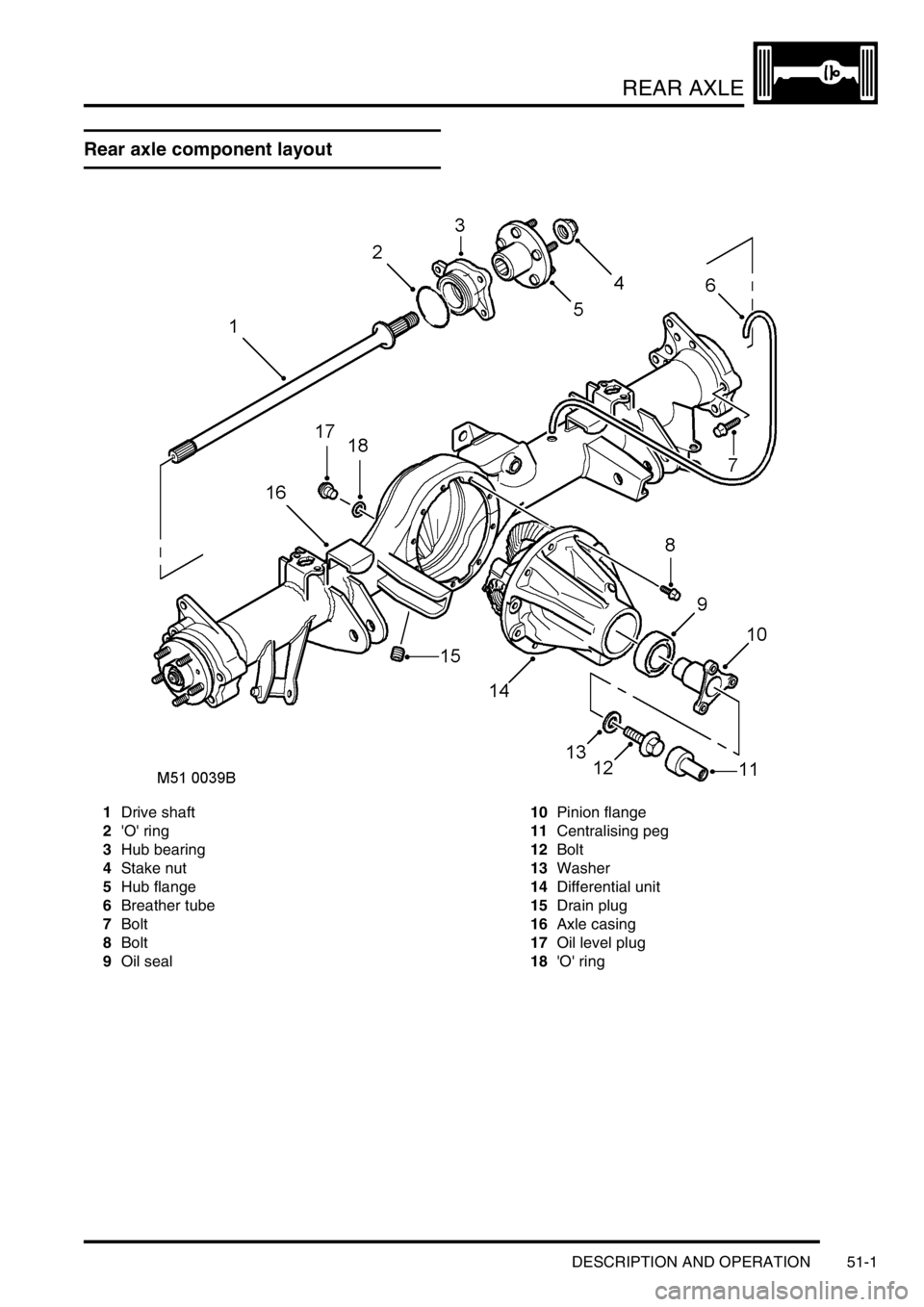
Rear axle component layout
1Drive shaft
2'O' ring
3Hub bearing
4Stake nut
5Hub flange
6Breather tube
7Bolt
8Bolt
9Oil seal10Pinion flange
11Centralising peg
12Bolt
13Washer
14Differential unit
15Drain plug
16Axle casing
17Oil level plug
18'O' ring
Page 861 of 1672

REAR AXLE
51-2 DESCRIPTION AND OPERATION
Description
General
The rear axle consists of an axle casing with a differential unit attached to the right of the vehicle centre line. A wheel
hub is installed in each end of the axle casing and connected to the differential unit by a drive shaft.
Axle casing
The axle casing is of welded construction, with brackets on the casing exterior for attachment to the rear suspension.
A differential cover on the rear of the axle casing contains an oil level plug for checking and replenishment of the
differential unit lubricating oil. A magnetic drain plug is installed on the underside of the axle casing.
The interior of the axle casing is ventilated through a breather tube inserted in a red plastic sleeve in the top of the
casing. The open end of the breather tube is located between the chassis and the left rear wheelarch.
Differential unit
The differential unit is of the spiral bevel type, lubricated by splash oil. The unit consists of a differential carrier
attached to a pinion housing. In the pinion housing, the pinion is splined to a pinion flange which is secured with a bolt
and washer. An oil seal prevents leakage past the pinion flange.
Centralising peg
The centralising peg is a press fit in the centre of the pinion flange and provides a positive location for the rear
propellor shaft to ensure it is centralised with the flange.