differential LAND ROVER DISCOVERY 2002 Owner's Guide
[x] Cancel search | Manufacturer: LAND ROVER, Model Year: 2002, Model line: DISCOVERY, Model: LAND ROVER DISCOVERY 2002Pages: 1672, PDF Size: 46.1 MB
Page 751 of 1672

TRANSFER BOX - LT230SE
41-18 DESCRIPTION AND OPERATION
On vehicle fitted with a differential lock, the high/low range selector lever as fitted on previous models also
incorporates the differential lock selector on vehicles from 03 model year.
The lever can be moved forwards or backwards to select high, neutral or low range or sideways to select differential
lock engaged or disengaged, on vehicles with differential lock fitted.
The selector lever assembly comprises an aluminium casting with bosses for location of the two cables, the selector
lever mechanism and a housing for the interlock solenoid (if fitted). The upper face of the casting has threaded holes
which allow for the attachment of the casting to the mounting plate which is attached to the transmission tunnel.
A boss at the front provides location for the differential lock cable. The cable is attached to a lever which in turn is
attached to the selector lever. Movement of the selector lever is passed via the lever to the cable which moves the
differential lock selector shaft.
A second boss provides for the location of the high/low range cable. The cable is attached to a plate which moves in
a forward or rearward direction with the selector lever. On North American and Japanese specification models, plate
movement is prevented by an interlock solenoid when the ignition key is not in the ignition.
When fitted, the interlock solenoid is located on the right hand side of the selector lever casting. The solenoid is fitted
into a cast housing in the casting and retained with a circlip. Sealant is applied over the circlip to seal the solenoid in
the housing to prevent the ingress of dirt and moisture. The solenoid performs the same function as on previous
models, preventing the selection of neutral on the transfer box when the ignition key is not in the ignition.
A setting procedure is required for both the differential lock cable and the high/low range cable.
Page 753 of 1672

TRANSFER BOX - LT230SE
41-20 DESCRIPTION AND OPERATION
Power flow - transfer box in HIGH ratio
Up to 03 Model Year section shown, from 03MY similar
The gearbox output shaft transmits power to the mainshaft input gear which is in constant mesh with one of the
intermediate gears. The intermediate gears are in constant mesh with the high and low range output gears running
on the differential rear shaft.
Power is transmitted to the output shafts via the differential assembly by locking either the high or low range gears to
the differential rear shaft. This is achieved by means of the high/low selector fork, sleeve and splined hub.
Page 758 of 1672

TRANSFER BOX - LT230SE
REPAIRS 41-25
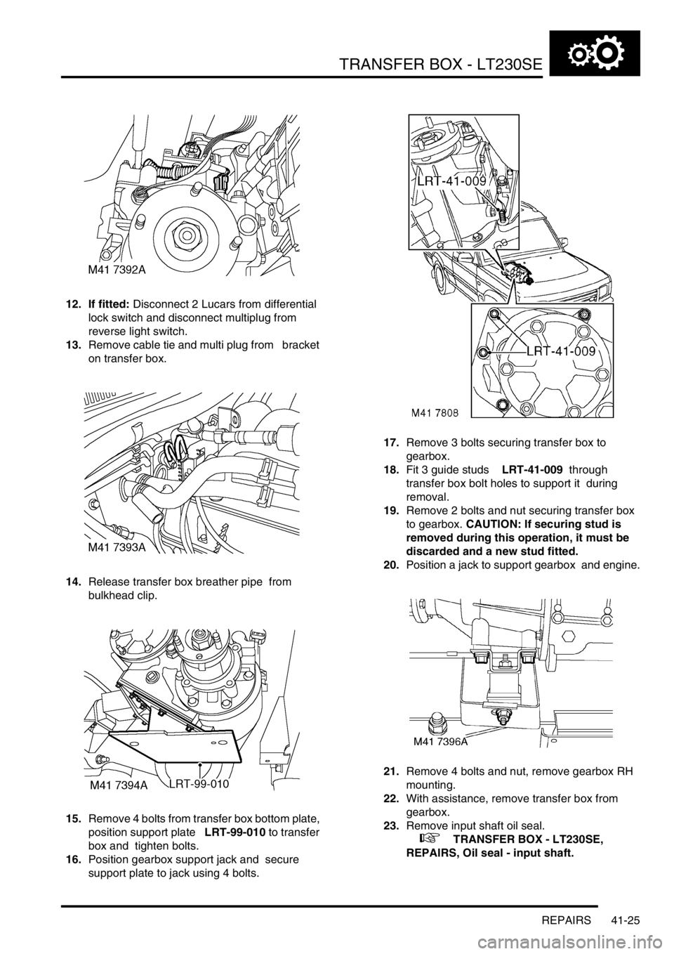
12. If fitted: Disconnect 2 Lucars from differential
lock switch and disconnect multiplug from
reverse light switch.
13.Remove cable tie and multi plug from bracket
on transfer box.
14.Release transfer box breather pipe from
bulkhead clip.
15.Remove 4 bolts from transfer box bottom plate,
position support plate LRT-99-010 to transfer
box and tighten bolts.
16.Position gearbox support jack and secure
support plate to jack using 4 bolts. 17.Remove 3 bolts securing transfer box to
gearbox.
18.Fit 3 guide studs LRT-41-009 through
transfer box bolt holes to support it during
removal.
19.Remove 2 bolts and nut securing transfer box
to gearbox. CAUTION: If securing stud is
removed during this operation, it must be
discarded and a new stud fitted.
20.Position a jack to support gearbox and engine.
21.Remove 4 bolts and nut, remove gearbox RH
mounting.
22.With assistance, remove transfer box from
gearbox.
23.Remove input shaft oil seal.
+ TRANSFER BOX - LT230SE,
REPAIRS, Oil seal - input shaft.
Page 759 of 1672

TRANSFER BOX - LT230SE
41-26 REPAIRS
Refit
1.Fit new input shaft oil seal.
+ TRANSFER BOX - LT230SE,
REPAIRS, Oil seal - input shaft.
2.Clean transfer box to gearbox mating faces.
3.Raise transfer box on jack and align to guide
studs LRT-41-009.
4.Clean transfer box to gearbox bolt threads.
5.Apply Loctite 290 to bolt and stud threads.
6.Fit and lightly tighten 2 bolts and nut securing
transfer box to gearbox. If new stud is to be
fitted, apply Loctite 290 to stud threads and
tighten to 45 Nm (33 lbf.ft).
7.Remove guide studs, fit and lightly tighten
remaining 3 bolts.
8.Tighten bolts and nut by diagonal selection to
45 Nm (33 lbf.ft).
9.Position gearbox RH mounting and tighten
bolts to 85 Nm (63 lbf.ft).
10.Tighten gearbox RH mounting nut to 48 Nm
(35 lbf.ft).
11.Remove 4 bolts securing support plate to
gearbox jack.
12.Remove 4 bolts securing support plate LRT-99-
010 to transfer box and remove plate.
13.Clean bottom plate bolt threads.
14.Apply Loctite 290 to threads of 4 bottom plate
bolts.
15.Fit 4 bolts securing bottom plate to transfer box
and tighten to 25 Nm (18 lbf.ft).
16.Position breather pipe and secure to bulkhead
clip.
17.Connect multiplug to reverse light switch.
18. If fitted - Connect Lucars to differential lock
switch.
19.Fit multiplug and cable tie to transfer gearbox
bracket. 20.Position high/low ratio selector cable and
secure with clevis pin.
21.Clean handbrake and mating face.
22.Position handbrake back plate and tighten
bolts to 75 Nm (55 lbf.ft).
23.Clean handbrake drum.
24.Fit handbrake drum and tighten retaining
screw.
25.Fit front propeller shaft.
+ PROPELLER SHAFTS, REPAIRS,
Propeller shaft - front.
26.Fit rear propeller shaft.
+ PROPELLER SHAFTS, REPAIRS,
Propeller shaft - rear.
27.Clean exhaust silencer and mating face.
28.Position silencer, fit new gasket , connect
mounting rubbers and tighten nuts to 40 Nm
(30 lbf.ft).
29.Refill transfer box with oil.
+ MAINTENANCE, PROCEDURES,
Transfer box.
30.Fit front exhaust pipe.
+ MANIFOLDS AND EXHAUST
SYSTEMS - Td5, REPAIRS, Pipe - front.
Page 761 of 1672

TRANSFER BOX - LT230SE
41-28 REPAIRS
11.Remove 2 cable ties securing cable to fuel
pipes.
12.Disconnect 2 Lucars from oil temperature
sensor and disconnect reverse lamp switch
multiplug.
13.Remove banjo bolt securing breather pipe and
discard washers.
14. If fitted - Disconnect 2 Lucars from differential
lock switch.
15.Release and disconnect transfer box neutral
switch multiplug. 16.Remove 4 bolts from transfer box bottom plate,
position support plate LRT-99-010 to transfer
box and tighten bolts.
17.Position gearbox support jack and secure
support plate to jack using 4 bolts.
18.Remove 3 bolts securing transfer box to
gearbox.
19.Fit 3 guide studs LRT-41-009 through transfer
box bolt holes to support it during removal.
20.Remove 2 bolts and nut securing transfer box
to gearbox case. If securing stud is removed
during this operation, it must be discarded
and a new stud fitted.
21.Position a jack to support gearbox and engine.
Page 762 of 1672

TRANSFER BOX - LT230SE
REPAIRS 41-29
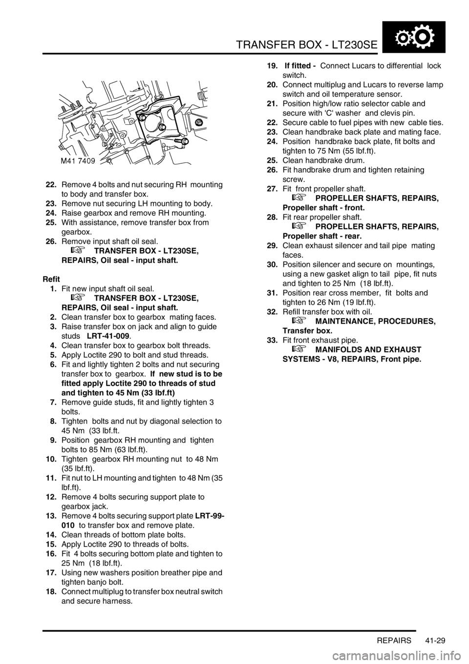
22.Remove 4 bolts and nut securing RH mounting
to body and transfer box.
23.Remove nut securing LH mounting to body.
24.Raise gearbox and remove RH mounting.
25.With assistance, remove transfer box from
gearbox.
26.Remove input shaft oil seal.
+ TRANSFER BOX - LT230SE,
REPAIRS, Oil seal - input shaft.
Refit
1.Fit new input shaft oil seal.
+ TRANSFER BOX - LT230SE,
REPAIRS, Oil seal - input shaft.
2.Clean transfer box to gearbox mating faces.
3.Raise transfer box on jack and align to guide
studs LRT-41-009.
4.Clean transfer box to gearbox bolt threads.
5.Apply Loctite 290 to bolt and stud threads.
6.Fit and lightly tighten 2 bolts and nut securing
transfer box to gearbox. If new stud is to be
fitted apply Loctite 290 to threads of stud
and tighten to 45 Nm (33 lbf.ft)
7.Remove guide studs, fit and lightly tighten 3
bolts.
8.Tighten bolts and nut by diagonal selection to
45 Nm (33 lbf.ft.
9.Position gearbox RH mounting and tighten
bolts to 85 Nm (63 lbf.ft).
10.Tighten gearbox RH mounting nut to 48 Nm
(35 lbf.ft).
11.Fit nut to LH mounting and tighten to 48 Nm (35
lbf.ft).
12.Remove 4 bolts securing support plate to
gearbox jack.
13.Remove 4 bolts securing support plate LRT-99-
010 to transfer box and remove plate.
14.Clean threads of bottom plate bolts.
15.Apply Loctite 290 to threads of bolts.
16.Fit 4 bolts securing bottom plate and tighten to
25 Nm (18 lbf.ft).
17.Using new washers position breather pipe and
tighten banjo bolt.
18.Connect multiplug to transfer box neutral switch
and secure harness. 19. If fitted - Connect Lucars to differential lock
switch.
20.Connect multiplug and Lucars to reverse lamp
switch and oil temperature sensor.
21.Position high/low ratio selector cable and
secure with 'C' washer and clevis pin.
22.Secure cable to fuel pipes with new cable ties.
23.Clean handbrake back plate and mating face.
24.Position handbrake back plate, fit bolts and
tighten to 75 Nm (55 lbf.ft).
25.Clean handbrake drum.
26.Fit handbrake drum and tighten retaining
screw.
27.Fit front propeller shaft.
+ PROPELLER SHAFTS, REPAIRS,
Propeller shaft - front.
28.Fit rear propeller shaft.
+ PROPELLER SHAFTS, REPAIRS,
Propeller shaft - rear.
29.Clean exhaust silencer and tail pipe mating
faces.
30.Position silencer and secure on mountings,
using a new gasket align to tail pipe, fit nuts
and tighten to 25 Nm (18 lbf.ft).
31.Position rear cross member, fit bolts and
tighten to 26 Nm (19 lbf.ft).
32.Refill transfer box with oil.
+ MAINTENANCE, PROCEDURES,
Transfer box.
33.Fit front exhaust pipe.
+ MANIFOLDS AND EXHAUST
SYSTEMS - V8, REPAIRS, Front pipe.
Page 763 of 1672

TRANSFER BOX - LT230SE
41-30 REPAIRS
Gasket - rear cover plate
$% 41.20.30
Remove
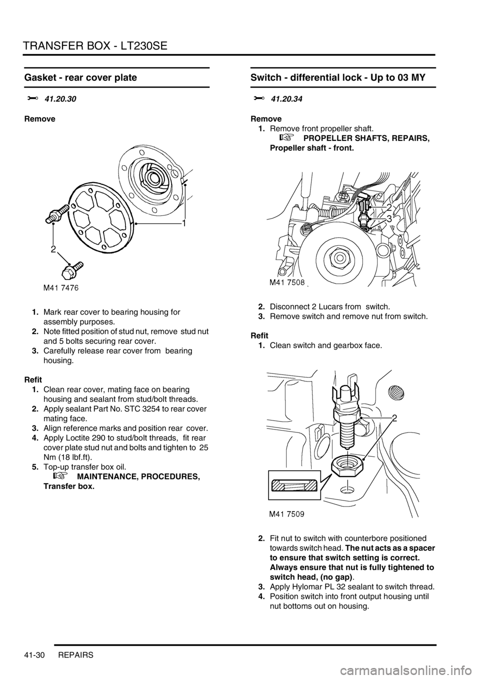
1.Mark rear cover to bearing housing for
assembly purposes.
2.Note fitted position of stud nut, remove stud nut
and 5 bolts securing rear cover.
3.Carefully release rear cover from bearing
housing.
Refit
1.Clean rear cover, mating face on bearing
housing and sealant from stud/bolt threads.
2.Apply sealant Part No. STC 3254 to rear cover
mating face.
3.Align reference marks and position rear cover.
4.Apply Loctite 290 to stud/bolt threads, fit rear
cover plate stud nut and bolts and tighten to 25
Nm (18 lbf.ft).
5.Top-up transfer box oil.
+ MAINTENANCE, PROCEDURES,
Transfer box.
Switch - differential lock - Up to 03 MY
$% 41.20.34
Remove
1.Remove front propeller shaft.
+ PROPELLER SHAFTS, REPAIRS,
Propeller shaft - front.
2.Disconnect 2 Lucars from switch.
3.Remove switch and remove nut from switch.
Refit
1.Clean switch and gearbox face.
2.Fit nut to switch with counterbore positioned
towards switch head. The nut acts as a spacer
to ensure that switch setting is correct.
Always ensure that nut is fully tightened to
switch head, (no gap).
3.Apply Hylomar PL 32 sealant to switch thread.
4.Position switch into front output housing until
nut bottoms out on housing.
Page 764 of 1672

TRANSFER BOX - LT230SE
REPAIRS 41-31
5.Tighten nut securing differential lock switch to
11 Nm (8 lbf.ft)
6.Connect Lucars to switch.
7.Fit front propeller shaft.
+ PROPELLER SHAFTS, REPAIRS,
Propeller shaft - front.
Cable - high/low selector
$% 41.20.43
Remove
1.Raise vehicle on a ramp.
2.Using a suitable crowsfoot spanner, remove
lock nut and washer securing outer cable to
abutment bracket.
3.Remove clevis pin securing inner cable to
transfer box lever and release cable from
abutment bracket.
4.Release 'C' clip securing outer cable to high/
low lever abutment bracket.
5.Remove clevis pin securing inner cable to high/
low lever.
Page 772 of 1672

TRANSFER BOX - LT230SE
OVERHAUL 41-39
OVERHAUL
Intermediate gear assembly
$% 41.20.10
Disassembly
1.Remove and discard 10 bolts securing bottom
cover, remove cover.
2.Remove and discard 7 bolts securing
differential lock selector side cover.
3.Remove side cover. 4.Release staking from intermediate shaft nut,
remove and discard nut.
5.Remove bolt securing intermediate shaft
retaining plate, remove plate.
6.Remove intermediate shaft and discard 2 'O'
rings.
Page 775 of 1672

TRANSFER BOX - LT230SE
41-42 OVERHAUL
18.Select neutral.
19.Screw a suitable bolt into tapped hole of tool
LRT-41-005.
20.Insert tool LRT-41-005 in end of mainshaft.
21.Using a suitable torque meter on tool LRT-41-
005, check torque to turn of gear train. Torque
to turn = 2.2 Nm (19 lbf.ft). If torque to turn
figure is incorrect, repeat intermediate gear
bearing pre-load setting and re-check.
22.On completion, remove tool LRT-41-005 and
stake flange of nut into recess on intermediate
shaft.
23.Clean transfer box bottom and side covers.
24.Apply sealant, Part No. STC 3254 to both
covers.
25.Clean bottom and side cover bolt threads.
26.Apply Loctite 290 to bolt threads.
27.Position side cover and tighten bolts to 25 Nm
(18 lbf.ft).
28.Position bottom cover and tighten bolts to 25
Nm (18 lbf.ft).
Differential assembly
$% 41.20.13
Remove
1.Remove intermediate gear cluster.
+ TRANSFER BOX - LT230SE,
OVERHAUL, Intermediate gear assembly.
2.Remove 6 bolts securing high/low cross shaft
housing to front output shaft housing and
remove housing.
3.Note position of longest bolt and remove 8 bolts
securing front output shaft housing to main
casing and remove housing.
Note: Carry out the following operations if
differential lock is fitted.