flywheel LAND ROVER DISCOVERY 2002 Workshop Manual
[x] Cancel search | Manufacturer: LAND ROVER, Model Year: 2002, Model line: DISCOVERY, Model: LAND ROVER DISCOVERY 2002Pages: 1672, PDF Size: 46.1 MB
Page 7 of 1672

CONTENTS
4CONTENTS
Crankshaft, sump and oil pump ...................................................................................................... 12-1-4
Cylinder head components ............................................................................................................. 12-1-6
Camshaft cover and engine cover .................................................................................................. 12-1-8
Camshaft timing chain components................................................................................................ 12-1-10
Description ...................................................................................................................................... 12-1-12
Lubrication circuit ............................................................................................................................ 12-1-29
ADJUSTMENTS
Engine oil pressure check .............................................................................................................. 12-1-35
REPAIRS
Pulley - crankshaft ........................................................................................................................ 12-1-37
Seal - crankshaft - rear ................................................................................................................. 12-1-38
Gasket - cylinder head .................................................................................................................. 12-1-39
Rocker shaft assembly ................................................................................................................... 12-1-44
Gasket - cover - camshaft .............................................................................................................. 12-1-46
Engine and ancillaries ................................................................................................................... 12-1-47
Mounting - front - LH ...................................................................................................................... 12-1-53
Mounting - front - RH ..................................................................................................................... 12-1-54
Mounting - engine - rear - LH ........................................................................................................ 12-1-55
Mounting - engine - rear - RH ......................................................................................................... 12-1-55
Flywheel ........................................................................................................................................ 12-1-56
Plate - drive - automatic ................................................................................................................. 12-1-56
Filter - oil ........................................................................................................................................ 12-1-57
Strainer - oil pick-up ....................................................................................................................... 12-1-58
Pump - oil........................................................................................................................................ 12-1-58
Gasket - sump ................................................................................................................................ 12-1-60
Valve - relief - oil pressure ............................................................................................................. 12-1-62
Switch - oil pressure ...................................................................................................................... 12-1-62
Cooler - engine oil .......................................................................................................................... 12-1-63
Gasket - centrifuge oil drain pipe .................................................................................................... 12-1-64
Rotor - centrifuge ........................................................................................................................... 12-1-66
Seal - oil - timing cover .................................................................................................................. 12-1-66
OVERHAUL
Gasket - inlet manifold ................................................................................................................... 12-1-69
Gasket - exhaust manifold ............................................................................................................. 12-1-70
Gasket - cylinder head .................................................................................................................. 12-1-71
Cylinder head - overhaul ............................................................................................................... 12-1-74
Gasket - engine sump ................................................................................................................... 12-1-84
Seal - crankshaft - rear - manual models........................................................................................ 12-1-86
Seal - crankshaft - rear - automatic models .................................................................................... 12-1-87
Flywheel.......................................................................................................................................... 12-1-88
Drive plate....................................................................................................................................... 12-1-88
Starter ring gear .............................................................................................................................. 12-1-89
Pump - oil ...................................................................................................................................... 12-1-90
Timing chain and sprockets ........................................................................................................... 12-1-93
Bearings - connecting rods ........................................................................................................... 12-1-96
Pistons, connecting rods and cylinder bores ................................................................................ 12-1-98
Crankshaft .................................................................................................................................... 12-1-102
ENGINE - V8 ............................................................................................. 12-2-1
DESCRIPTION AND OPERATION
V8 Engine ....................................................................................................................................... 12-2-1
Cylinder head components ............................................................................................................. 12-2-2
Cylinder block components............................................................................................................. 12-2-4
Page 8 of 1672

CONTENTS
CONTENTS 5
Description ...................................................................................................................................... 12-2-6
ADJUSTMENTS
Engine oil pressure check .............................................................................................................. 12-2-11
REPAIRS
Seal - crankshaft - rear .................................................................................................................. 12-2-13
Gasket - cylinder head - LH ........................................................................................................... 12-2-14
Gasket - cylinder head - RH ............................................................................................................ 12-2-16
Gasket - rocker cover - LH ............................................................................................................ 12-2-19
Gasket - rocker cover - RH ............................................................................................................ 12-2-20
Mounting - front - LH ...................................................................................................................... 12-2-22
Mounting - front - RH ..................................................................................................................... 12-2-23
Mounting - rear - LH ....................................................................................................................... 12-2-24
Mounting - rear - RH ...................................................................................................................... 12-2-25
Engine assembly............................................................................................................................. 12-2-26
Flywheel ........................................................................................................................................ 12-2-31
Plate - drive - automatic ................................................................................................................ 12-2-32
Ring gear - starter ......................................................................................................................... 12-2-33
Filter - oil ....................................................................................................................................... 12-2-34
Strainer - oil pick-up ...................................................................................................................... 12-2-35
Pump - oil ...................................................................................................................................... 12-2-35
Gasket - sump ................................................................................................................................ 12-2-36
Switch - oil pressure ....................................................................................................................... 12-2-38
Cooler - engine oil .......................................................................................................................... 12-2-39
Gasket - timing gear cover ............................................................................................................ 12-2-40
Seal - cover - timing gears ............................................................................................................ 12-2-42
OVERHAUL
Gasket - inlet manifold ................................................................................................................... 12-2-45
Gasket - exhaust manifold ............................................................................................................. 12-2-48
Seal - crankshaft - rear - automatic models .................................................................................... 12-2-49
Seal - crankshaft - rear - manual models ........................................................................................ 12-2-50
Bearing - spigot - crankshaft .......................................................................................................... 12-2-52
Gasket - engine sump .................................................................................................................... 12-2-53
Strainer - oil pick-up ....................................................................................................................... 12-2-54
Seal - timing gear cover ................................................................................................................. 12-2-54
Gasket - timing gear cover ............................................................................................................. 12-2-55
Timing chain and gears .................................................................................................................. 12-2-57
Rocker shaft - overhaul ................................................................................................................. 12-2-59
Gasket - cylinder head .................................................................................................................... 12-2-60
Cylinder head - overhaul ................................................................................................................ 12-2-62
Piston assemblies ........................................................................................................................... 12-2-67
Bearings - connecting rods ............................................................................................................ 12-2-71
Crankshaft and main bearings ........................................................................................................ 12-2-72
Camshaft ....................................................................................................................................... 12-2-76
EMISSION CONTROL - Td5..................................................................... 17-1-1
DESCRIPTION AND OPERATION
EGR system components - type 1 .................................................................................................. 17-1-1
EGR system components - type 2 .................................................................................................. 17-1-2
Emission Control Systems .............................................................................................................. 17-1-4
Crankcase emission control ............................................................................................................ 17-1-4
Exhaust gas recirculation ................................................................................................................ 17-1-5
Page 32 of 1672
INTRODUCTION
01-3
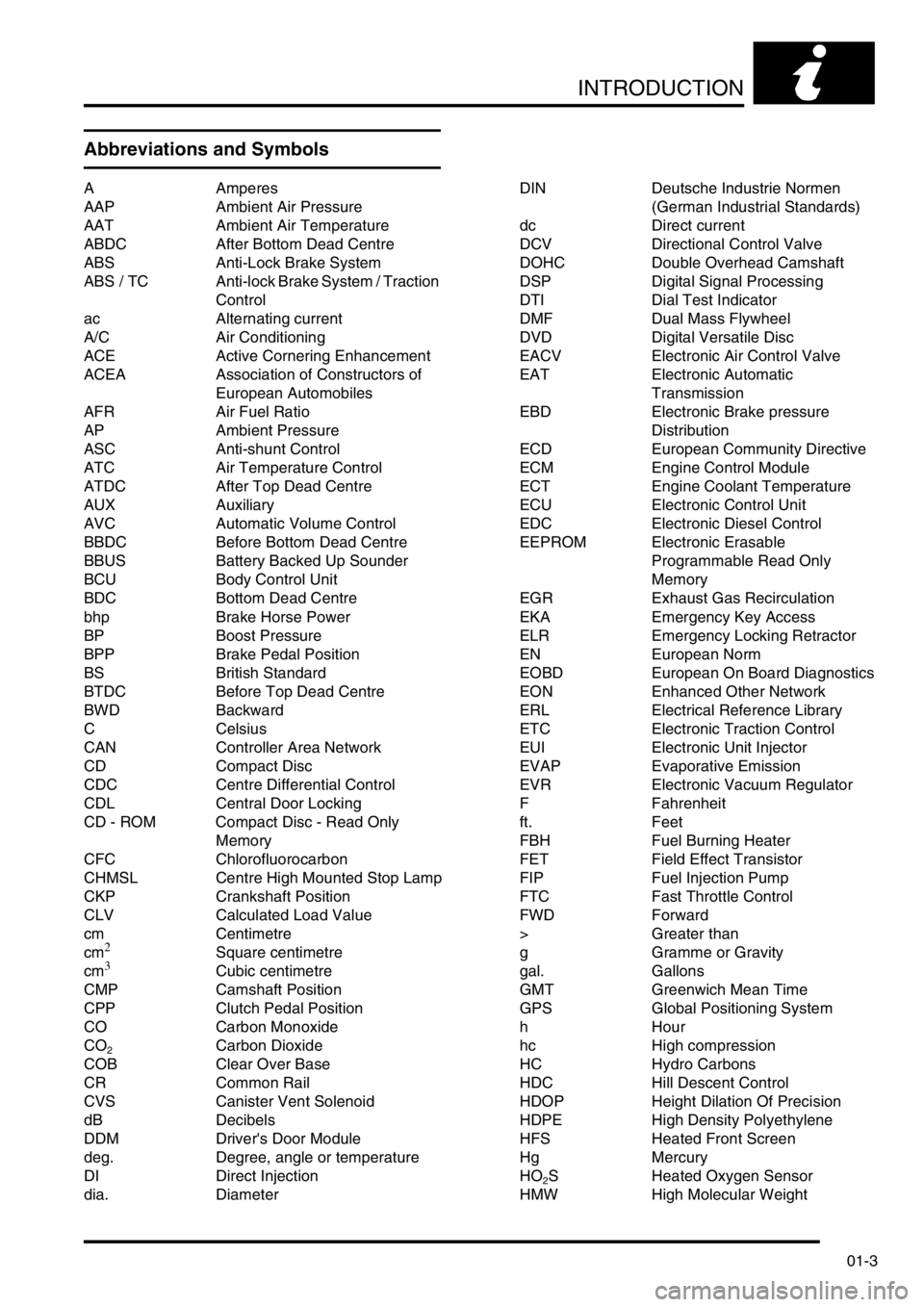
Abbreviations and Symbols
A Amperes
AAP Ambient Air Pressure
AAT Ambient Air Temperature
ABDC After Bottom Dead Centre
ABS Anti-Lock Brake System
ABS / TC Anti-lock Brake System / Traction
Control
ac Alternating current
A/C Air Conditioning
ACE Active Cornering Enhancement
ACEA Association of Constructors of
European Automobiles
AFR Air Fuel Ratio
AP Ambient Pressure
ASC Anti-shunt Control
ATC Air Temperature Control
ATDC After Top Dead Centre
AUX Auxiliary
AVC Automatic Volume Control
BBDC Before Bottom Dead Centre
BBUS Battery Backed Up Sounder
BCU Body Control Unit
BDC Bottom Dead Centre
bhp Brake Horse Power
BP Boost Pressure
BPP Brake Pedal Position
BS British Standard
BTDC Before Top Dead Centre
BWD Backward
C Celsius
CAN Controller Area Network
CD Compact Disc
CDC Centre Differential Control
CDL Central Door Locking
CD - ROM Compact Disc - Read Only
Memory
CFC Chlorofluorocarbon
CHMSL Centre High Mounted Stop Lamp
CKP Crankshaft Position
CLV Calculated Load Value
cm Centimetre
cm
2Square centimetre
cm3Cubic centimetre
CMP Camshaft Position
CPP Clutch Pedal Position
CO Carbon Monoxide
CO
2Carbon Dioxide
COB Clear Over Base
CR Common Rail
CVS Canister Vent Solenoid
dB Decibels
DDM Driver's Door Module
deg. Degree, angle or temperature
DI Direct Injection
dia. DiameterDIN Deutsche Industrie Normen
(German Industrial Standards)
dc Direct current
DCV Directional Control Valve
DOHC Double Overhead Camshaft
DSP Digital Signal Processing
DTI Dial Test Indicator
DMF Dual Mass Flywheel
DVD Digital Versatile Disc
EACV Electronic Air Control Valve
EAT Electronic Automatic
Transmission
EBD Electronic Brake pressure
Distribution
ECD European Community Directive
ECM Engine Control Module
ECT Engine Coolant Temperature
ECU Electronic Control Unit
EDC Electronic Diesel Control
EEPROM Electronic Erasable
Programmable Read Only
Memory
EGR Exhaust Gas Recirculation
EKA Emergency Key Access
ELR Emergency Locking Retractor
EN European Norm
EOBD European On Board Diagnostics
EON Enhanced Other Network
ERL Electrical Reference Library
ETC Electronic Traction Control
EUI Electronic Unit Injector
EVAP Evaporative Emission
EVR Electronic Vacuum Regulator
F Fahrenheit
ft. Feet
FBH Fuel Burning Heater
FET Field Effect Transistor
FIP Fuel Injection Pump
FTC Fast Throttle Control
FWD Forward
> Greater than
g Gramme or Gravity
gal. Gallons
GMT Greenwich Mean Time
GPS Global Positioning System
hHour
hc High compression
HC Hydro Carbons
HDC Hill Descent Control
HDOP Height Dilation Of Precision
HDPE High Density Polyethylene
HFS Heated Front Screen
Hg Mercury
HO
2S Heated Oxygen Sensor
HMW High Molecular Weight
Page 47 of 1672
GENERAL INFORMATION
03-12
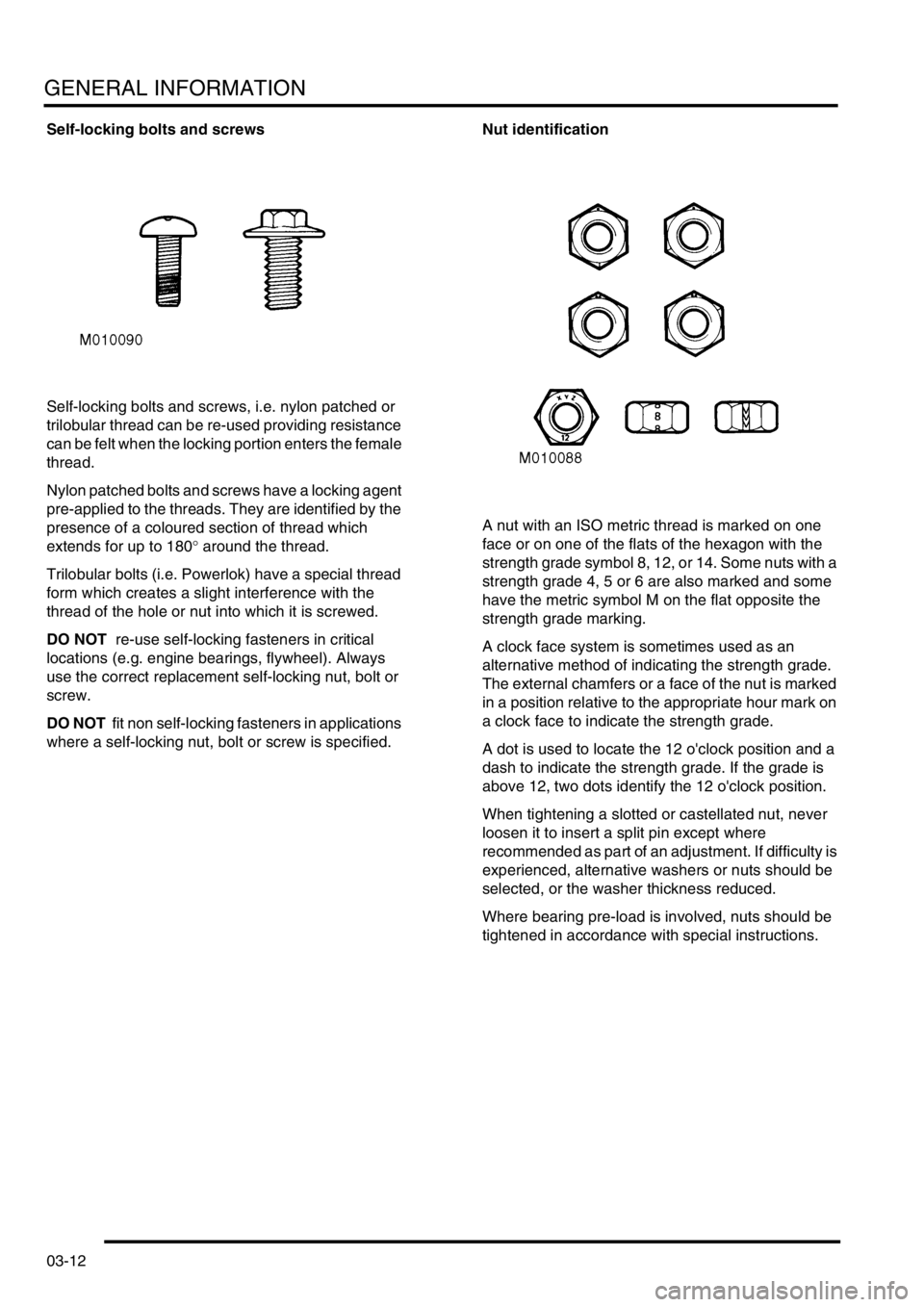
Self-locking bolts and screws
Self-locking bolts and screws, i.e. nylon patched or
trilobular thread can be re-used providing resistance
can be felt when the locking portion enters the female
thread.
Nylon patched bolts and screws have a locking agent
pre-applied to the threads. They are identified by the
presence of a coloured section of thread which
extends for up to 180
° around the thread.
Trilobular bolts (i.e. Powerlok) have a special thread
form which creates a slight interference with the
thread of the hole or nut into which it is screwed.
DO NOT re-use self-locking fasteners in critical
locations (e.g. engine bearings, flywheel). Always
use the correct replacement self-locking nut, bolt or
screw.
DO NOT fit non self-locking fasteners in applications
where a self-locking nut, bolt or screw is specified.Nut identification
A nut with an ISO metric thread is marked on one
face or on one of the flats of the hexagon with the
strength grade symbol 8, 12, or 14. Some nuts with a
strength grade 4, 5 or 6 are also marked and some
have the metric symbol M on the flat opposite the
strength grade marking.
A clock face system is sometimes used as an
alternative method of indicating the strength grade.
The external chamfers or a face of the nut is marked
in a position relative to the appropriate hour mark on
a clock face to indicate the strength grade.
A dot is used to locate the 12 o'clock position and a
dash to indicate the strength grade. If the grade is
above 12, two dots identify the 12 o'clock position.
When tightening a slotted or castellated nut, never
loosen it to insert a split pin except where
recommended as part of an adjustment. If difficulty is
experienced, alternative washers or nuts should be
selected, or the washer thickness reduced.
Where bearing pre-load is involved, nuts should be
tightened in accordance with special instructions.
Page 87 of 1672
TORQUE WRENCH SETTINGS
06-2
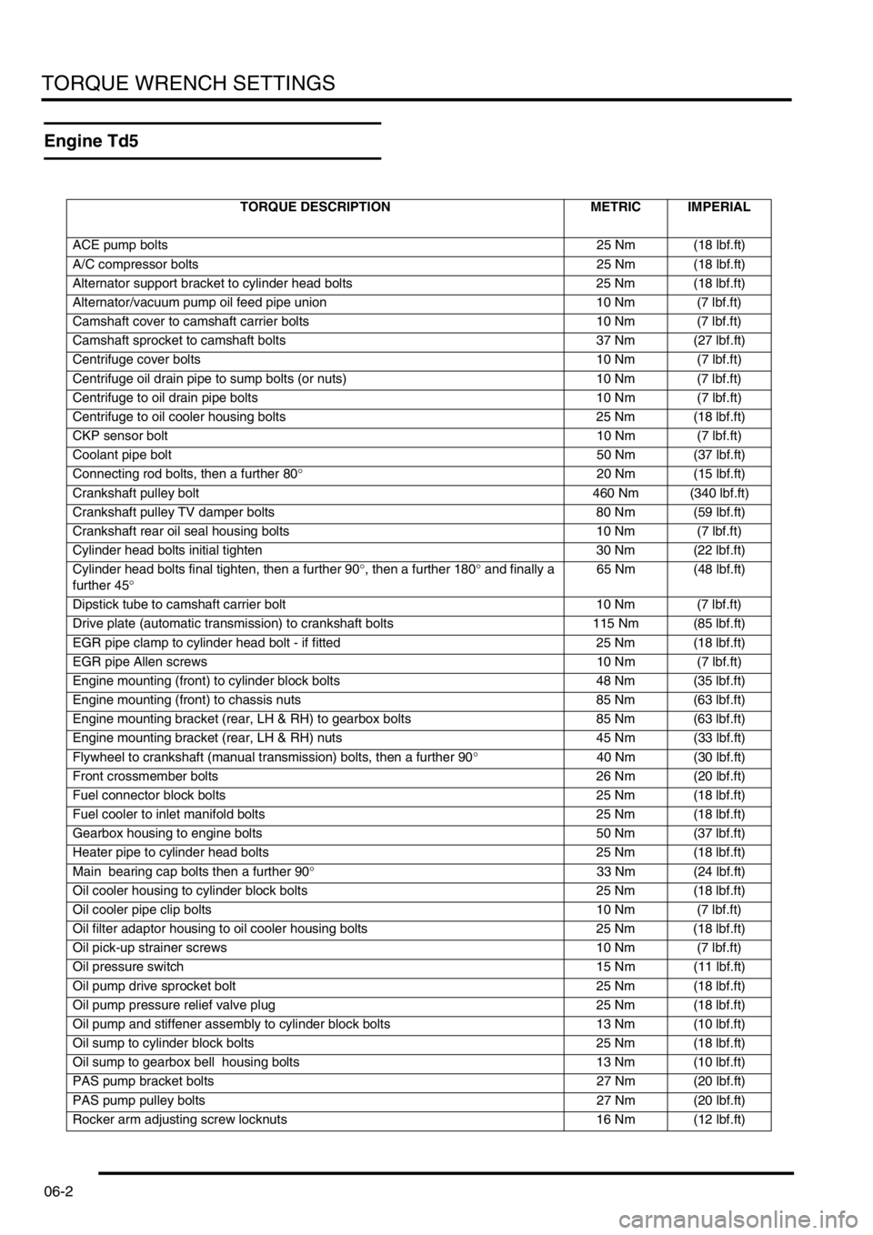
Engine Td5
TORQUE DESCRIPTION METRIC IMPERIAL
ACE pump bolts25 Nm (18 lbf.ft)
A/C compressor bolts 25 Nm (18 lbf.ft)
Alternator support bracket to cylinder head bolts 25 Nm (18 lbf.ft)
Alternator/vacuum pump oil feed pipe union 10 Nm (7 lbf.ft)
Camshaft cover to camshaft carrier bolts 10 Nm (7 lbf.ft)
Camshaft sprocket to camshaft bolts 37 Nm (27 lbf.ft)
Centrifuge cover bolts 10 Nm (7 lbf.ft)
Centrifuge oil drain pipe to sump bolts (or nuts) 10 Nm (7 lbf.ft)
Centrifuge to oil drain pipe bolts 10 Nm (7 lbf.ft)
Centrifuge to oil cooler housing bolts 25 Nm (18 lbf.ft)
CKP sensor bolt10 Nm (7 lbf.ft)
Coolant pipe bolt50 Nm (37 lbf.ft)
Connecting rod bolts, then a further 80°20 Nm (15 lbf.ft)
Crankshaft pulley bolt 460 Nm (340 lbf.ft)
Crankshaft pulley TV damper bolts 80 Nm (59 lbf.ft)
Crankshaft rear oil seal housing bolts 10 Nm (7 lbf.ft)
Cylinder head bolts initial tighten 30 Nm (22 lbf.ft)
Cylinder head bolts final tighten, then a further 90°, then a further 180° and finally a
further 45°65 Nm (48 lbf.ft)
Dipstick tube to camshaft carrier bolt 10 Nm (7 lbf.ft)
Drive plate (automatic transmission) to crankshaft bolts 115 Nm (85 lbf.ft)
EGR pipe clamp to cylinder head bolt - if fitted 25 Nm (18 lbf.ft)
EGR pipe Allen screws 10 Nm (7 lbf.ft)
Engine mounting (front) to cylinder block bolts 48 Nm (35 lbf.ft)
Engine mounting (front) to chassis nuts 85 Nm (63 lbf.ft)
Engine mounting bracket (rear, LH & RH) to gearbox bolts 85 Nm (63 lbf.ft)
Engine mounting bracket (rear, LH & RH) nuts 45 Nm (33 lbf.ft)
Flywheel to crankshaft (manual transmission) bolts, then a further 90°40 Nm (30 lbf.ft)
Front crossmember bolts 26 Nm (20 lbf.ft)
Fuel connector block bolts 25 Nm (18 lbf.ft)
Fuel cooler to inlet manifold bolts 25 Nm (18 lbf.ft)
Gearbox housing to engine bolts 50 Nm (37 lbf.ft)
Heater pipe to cylinder head bolts 25 Nm (18 lbf.ft)
Main bearing cap bolts then a further 90°33 Nm (24 lbf.ft)
Oil cooler housing to cylinder block bolts 25 Nm (18 lbf.ft)
Oil cooler pipe clip bolts 10 Nm (7 lbf.ft)
Oil filter adaptor housing to oil cooler housing bolts 25 Nm (18 lbf.ft)
Oil pick-up strainer screws 10 Nm (7 lbf.ft)
Oil pressure switch 15 Nm (11 lbf.ft)
Oil pump drive sprocket bolt 25 Nm (18 lbf.ft)
Oil pump pressure relief valve plug 25 Nm (18 lbf.ft)
Oil pump and stiffener assembly to cylinder block bolts 13 Nm (10 lbf.ft)
Oil sump to cylinder block bolts 25 Nm (18 lbf.ft)
Oil sump to gearbox bell housing bolts 13 Nm (10 lbf.ft)
PAS pump bracket bolts 27 Nm (20 lbf.ft)
PAS pump pulley bolts 27 Nm (20 lbf.ft)
Rocker arm adjusting screw locknuts 16 Nm (12 lbf.ft)
Page 89 of 1672
TORQUE WRENCH SETTINGS
06-4
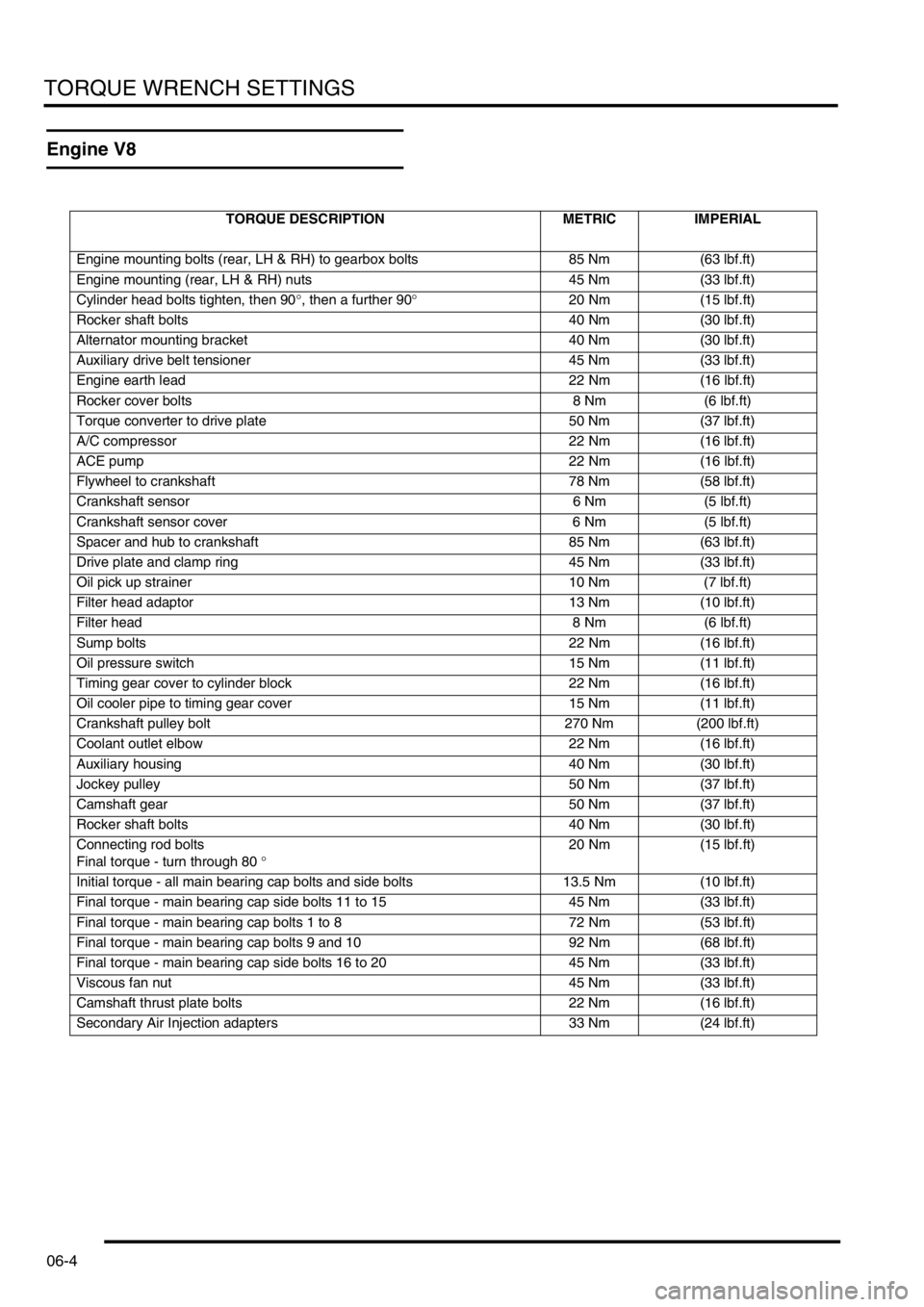
Engine V8
TORQUE DESCRIPTION METRIC IMPERIAL
Engine mounting bolts (rear, LH & RH) to gearbox bolts 85 Nm (63 lbf.ft)
Engine mounting (rear, LH & RH) nuts 45 Nm (33 lbf.ft)
Cylinder head bolts tighten, then 90°, then a further 90°20 Nm (15 lbf.ft)
Rocker shaft bolts 40 Nm (30 lbf.ft)
Alternator mounting bracket 40 Nm (30 lbf.ft)
Auxiliary drive belt tensioner 45 Nm (33 lbf.ft)
Engine earth lead 22 Nm (16 lbf.ft)
Rocker cover bolts 8 Nm (6 lbf.ft)
Torque converter to drive plate 50 Nm (37 lbf.ft)
A/C compressor 22 Nm (16 lbf.ft)
ACE pump 22 Nm (16 lbf.ft)
Flywheel to crankshaft 78 Nm (58 lbf.ft)
Crankshaft sensor 6 Nm (5 lbf.ft)
Crankshaft sensor cover 6 Nm (5 lbf.ft)
Spacer and hub to crankshaft 85 Nm (63 lbf.ft)
Drive plate and clamp ring 45 Nm (33 lbf.ft)
Oil pick up strainer 10 Nm (7 lbf.ft)
Filter head adaptor 13 Nm (10 lbf.ft)
Filter head 8 Nm (6 lbf.ft)
Sump bolts 22 Nm (16 lbf.ft)
Oil pressure switch 15 Nm (11 lbf.ft)
Timing gear cover to cylinder block 22 Nm (16 lbf.ft)
Oil cooler pipe to timing gear cover 15 Nm (11 lbf.ft)
Crankshaft pulley bolt 270 Nm (200 lbf.ft)
Coolant outlet elbow 22 Nm (16 lbf.ft)
Auxiliary housing 40 Nm (30 lbf.ft)
Jockey pulley 50 Nm (37 lbf.ft)
Camshaft gear 50 Nm (37 lbf.ft)
Rocker shaft bolts 40 Nm (30 lbf.ft)
Connecting rod bolts
Final torque - turn through 80 °20 Nm (15 lbf.ft)
Initial torque - all main bearing cap bolts and side bolts 13.5 Nm (10 lbf.ft)
Final torque - main bearing cap side bolts 11 to 15 45 Nm (33 lbf.ft)
Final torque - main bearing cap bolts 1 to 8 72 Nm (53 lbf.ft)
Final torque - main bearing cap bolts 9 and 10 92 Nm (68 lbf.ft)
Final torque - main bearing cap side bolts 16 to 20 45 Nm (33 lbf.ft)
Viscous fan nut 45 Nm (33 lbf.ft)
Camshaft thrust plate bolts 22 Nm (16 lbf.ft)
Secondary Air Injection adapters 33 Nm (24 lbf.ft)
Page 144 of 1672
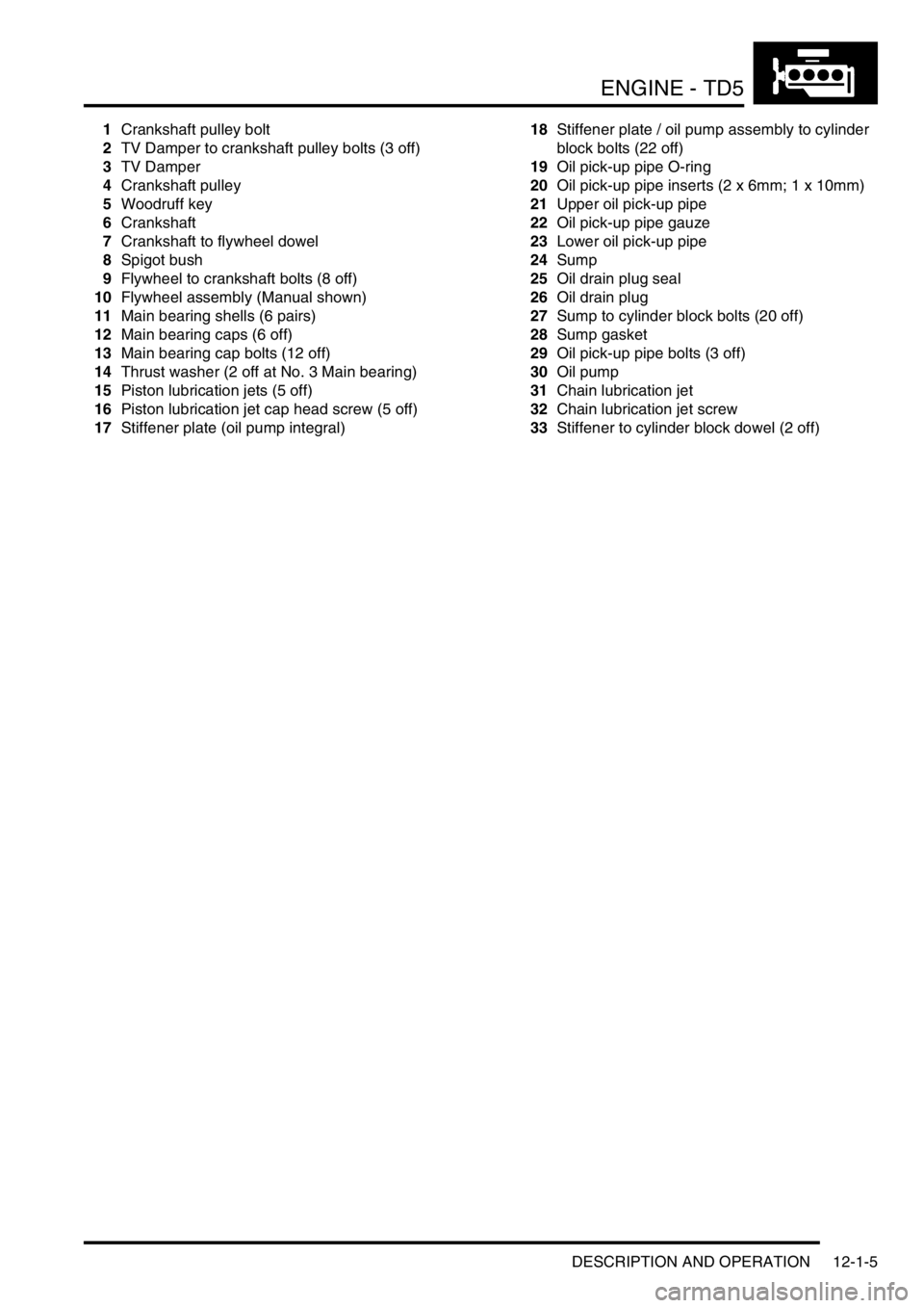
ENGINE - TD5
DESCRIPTION AND OPERATION 12-1-5
1Crankshaft pulley bolt
2TV Damper to crankshaft pulley bolts (3 off)
3TV Damper
4Crankshaft pulley
5Woodruff key
6Crankshaft
7Crankshaft to flywheel dowel
8Spigot bush
9Flywheel to crankshaft bolts (8 off)
10Flywheel assembly (Manual shown)
11Main bearing shells (6 pairs)
12Main bearing caps (6 off)
13Main bearing cap bolts (12 off)
14Thrust washer (2 off at No. 3 Main bearing)
15Piston lubrication jets (5 off)
16Piston lubrication jet cap head screw (5 off)
17Stiffener plate (oil pump integral)18Stiffener plate / oil pump assembly to cylinder
block bolts (22 off)
19Oil pick-up pipe O-ring
20Oil pick-up pipe inserts (2 x 6mm; 1 x 10mm)
21Upper oil pick-up pipe
22Oil pick-up pipe gauze
23Lower oil pick-up pipe
24Sump
25Oil drain plug seal
26Oil drain plug
27Sump to cylinder block bolts (20 off)
28Sump gasket
29Oil pick-up pipe bolts (3 off)
30Oil pump
31Chain lubrication jet
32Chain lubrication jet screw
33Stiffener to cylinder block dowel (2 off)
Page 151 of 1672
ENGINE - TD5
12-1-12 DESCRIPTION AND OPERATION
Description
General
The Td5 diesel engine is a 2.5 litre, 5 cylinder, in-line direct injection unit having 2 valves per cylinder, operated by a
single overhead camshaft. The engine emissions, on pre EU3 models, comply with ECD2 (European Commission
Directive) and on EU3 models, comply with ECD3 legislative requirements. Both models employ electronic engine
management control, positive crankcase ventilation and exhaust gas recirculation to limit the emission of pollutants.
The unit is water cooled and turbo-charged and is controlled by an electronic engine management system.
The engine is a monobloc cast iron construction with an aluminium stiffening plate fitted to the bottom of the cylinder
block to improve lower structure rigidity. The cylinder head and sump are cast aluminium. An acoustic cover is fitted
over the upper engine to reduce engine generated noise.
The engine utilises the following features:
lElectronic Unit Injectors (EUI's) controlled by an Engine Management System for precise fuel delivery under
all prevailing operating conditions.
lTurbocharging which delivers compressed air to the combustion chambers via an intercooler for improved
power output.
lFuel Cooler
lOil Cooler
lCentrifuge Oil Filter
lHydraulic Lash Adjusters with independent finger followers
Cylinder block components
The cylinder block components are described below:
Cylinder Block
The cylinders and crankcase are contained in a single cast iron construction. The cylinders are direct bored and
plateau honed with lubrication oil supplied via lubrication jets for piston and gudgeon pin lubrication and cooling. It is
not possible to rebore the cylinder block if the cylinders become worn or damaged. Three metal core plugs are fitted
to the three centre cylinders on the right hand side of the cylinder block.
Lubrication oil is distributed throughout the block via the main oil gallery to critical moving parts through channels
bored in the block which divert oil to the main and big-end bearings via oil holes machined into the crankshaft. Oil is
also supplied from the cylinder block main gallery to the five lubrication jets which cool and lubricate the piston and
gudgeon pins. Plugs are used to seal both ends of the main oil gallery at front and rear of the engine block. An oil
cooler is fitted to the LH side of the engine block; ports in the oil cooler assembly mate with ports in the cylinder block
to facilitate coolant flow. Oil is diverted through the oil cooler, centrifuge filter and full-flow filter before supplying the
main oil gallery. A tapping in the oil filter housing provides a lubrication source for the turbocharger bearings and an
oil pressure switch is included in a tapping in the oil cooler housing which determines whether sufficient oil pressure
is available to provide engine lubrication and cooling.
Cylinder cooling is achieved by water circulating through chambers in the engine block casting. A threaded coolant
jacket plug is located at the front RH side of the cylinder block.
Cast mounting brackets are bolted to both sides of the engine block for mounting the engine to the chassis on the LH
and RH hydramount studs.
The gearbox bolts directly to the engine block; a gearbox shim plate is located between the adjoining faces of the
gearbox and the flywheel side of the engine block and is fixed to the rear of the engine block by two bolts. Two hollow
metal dowels locate the rear of the cylinder block to the gearbox shim plate. The gearbox casing provides the
mounting for the starter motor.
A port is included at the rear left hand side of the cylinder block which connects to the turbocharger oil drain pipe to
return lubrication oil to the sump.
A plug sealing the lubrication cross-drilling gallery is located at the front right hand side of the cylinder block and plugs
for the main lubrication gallery is included at the front and rear of the cylinder block.
Page 160 of 1672
ENGINE - TD5
DESCRIPTION AND OPERATION 12-1-21
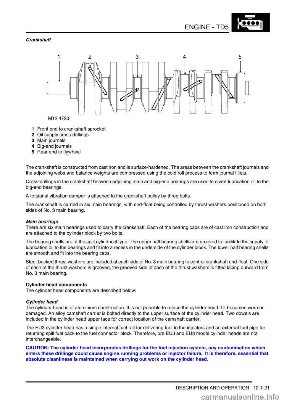
Crankshaft
1Front end to crankshaft sprocket
2Oil supply cross-drillings
3Main journals
4Big-end journals
5Rear end to flywheel
The crankshaft is constructed from cast iron and is surface-hardened. The areas between the crankshaft journals and
the adjoining webs and balance weights are compressed using the cold roll process to form journal fillets.
Cross-drillings in the crankshaft between adjoining main and big-end bearings are used to divert lubrication oil to the
big-end bearings.
A torsional vibration damper is attached to the crankshaft pulley by three bolts.
The crankshaft is carried in six main bearings, with end-float being controlled by thrust washers positioned on both
sides of No. 3 main bearing.
Main bearings
There are six main bearings used to carry the crankshaft. Each of the bearing caps are of cast iron construction and
are attached to the cylinder block by two bolts.
The bearing shells are of the split cylindrical type. The upper half bearing shells are grooved to facilitate the supply of
lubrication oil to the bearings and fit into a recess in the underside of the cylinder block. The lower half bearing shells
are smooth and fit into the bearing caps.
Steel-backed thrust washers are included at each side of No. 3 main bearing to control crankshaft end-float. One side
of each of the thrust washers is grooved, the grooved side of each of the thrust washers is fitted facing outward from
No. 3 main bearing.
Cylinder head components
The cylinder head components are described below:
Cylinder head
The cylinder head is of aluminium construction. It is not possible to reface the cylinder head if it becomes worn or
damaged. An alloy camshaft carrier is bolted directly to the upper surface of the cylinder head. Two dowels are
included in the cylinder head upper face for correct location of the camshaft carrier.
The EU3 cylinder head has a single internal fuel rail for delivering fuel to the injectors and an external fuel pipe for
returning spill fuel back to the fuel connector block. Therefore, pre EU3 and EU3 model cylinder heads are not
interchangeable.
CAUTION: The cylinder head incorporates drillings for the fuel injection system, any contamination which
enters these drillings could cause engine running problems or injector failure. It is therefore, essential that
absolute cleanliness is maintained when carrying out work on the cylinder head.
Page 177 of 1672

ENGINE - TD5
12-1-38 REPAIRS
Seal - crankshaft - rear
$% 12.21.20
Remove
1. Automatic models: Remove drive plate
+ ENGINE - Td5, REPAIRS, Plate -
drive - automatic.
2. Manual models: Remove flywheel.
+ ENGINE - Td5, REPAIRS, Flywheel.
3.Remove sump gasket.
+ ENGINE - Td5, REPAIRS, Gasket -
sump.
4.Remove 5 bolts securing crankshaft oil seal
housing to cylinder block.
5.Remove crankshaft oil seal housing.
Refit
1.Clean interface between crankshaft oil seal
housing and cylinder block.
2.Position seal protector, LRT-12-061 over
crankshaft boss. Fit new seal and remove tool
LRT-12-061 .
CAUTION: Oil seal must be fitted dry.3.Fit crankshaft rear oil seal housing bolts and
using sequence shown, tighten to 9 Nm (7
lbf.ft).
4.Fit new sump gasket.
+ ENGINE - Td5, REPAIRS, Gasket -
sump.
5. Automatic models: Fit drive plate
+ ENGINE - Td5, REPAIRS, Plate -
drive - automatic.
6. Manual models: Fit flywheel.
+ ENGINE - Td5, REPAIRS, Flywheel.