warning LAND ROVER DISCOVERY 2002 Workshop Manual
[x] Cancel search | Manufacturer: LAND ROVER, Model Year: 2002, Model line: DISCOVERY, Model: LAND ROVER DISCOVERY 2002Pages: 1672, PDF Size: 46.1 MB
Page 5 of 1672

CONTENTS
2CONTENTS
IDENTIFICATION NUMBERS .................................................................. 05-1
Vehicle Identification Number ......................................................................................................... 05-1
Identification Number Locations ..................................................................................................... 05-3
TORQUE WRENCH SETTINGS .............................................................. 06-1
Maintenance ................................................................................................................................... 06-1
Engine Td5 ..................................................................................................................................... 06-2
Engine V8 ....................................................................................................................................... 06-4
Emission control - Td5 .................................................................................................................... 06-5
Emission control - V8 ...................................................................................................................... 06-5
Engine management system - Td5 ................................................................................................. 06-5
Engine management system - V8................................................................................................... 06-6
Cooling system ............................................................................................................................... 06-6
Manifolds and exhaust systems - Td5 ............................................................................................ 06-6
Manifolds and exhaust systems - V8 .............................................................................................. 06-7
Clutch.............................................................................................................................................. 06-7
Manual gearbox - R380 .................................................................................................................. 06-8
Transfer box - LT230SE ................................................................................................................. 06-8
Automatic gearbox - ZF4HP22/24 .................................................................................................. 06-9
Propeller shafts ............................................................................................................................... 06-9
Axles ............................................................................................................................................... 06-9
Steering .......................................................................................................................................... 06-10
Front suspension ............................................................................................................................ 06-11
Rear suspension ............................................................................................................................. 06-12
Brakes............................................................................................................................................. 06-12
Restraint systems ........................................................................................................................... 06-13
Body................................................................................................................................................ 06-14
Heating and air conditioning ........................................................................................................... 06-15
Wipers and washers ....................................................................................................................... 06-15
Electrical ......................................................................................................................................... 06-15
LIFTING AND TOWING ........................................................................... 08-1
LIFTING .......................................................................................................................................... 08-1
TOWING ......................................................................................................................................... 08-2
TRANSPORTING ........................................................................................................................... 08-3
CAPACITIES, FLUIDS AND LUBRICANTS ............................................ 09-1
Capacities ....................................................................................................................................... 09-1
Fluids .............................................................................................................................................. 09-2
Anti-Freeze Concentration .............................................................................................................. 09-3
Lubrication ...................................................................................................................................... 09-3
MAINTENANCE ........................................................................................ 10-1
PROCEDURES
V8 engine underbonnet view .......................................................................................................... 10-1
Diesel underbonnet view ................................................................................................................ 10-2
Seats and seat belts ...................................................................................................................... 10-3
Lamps, horns and warning indicators ........................................................................................... 10-5
Wipers and washers ...................................................................................................................... 10-5
Handbrake .................................................................................................................................. 10-6
Page 15 of 1672

CONTENTS
12 CONTENTS
Operation ........................................................................................................................................ 41-19
ADJUSTMENTS
Cable - high/low selector ................................................................................................................ 41-21
REPAIRS
Bottom cover - transfer box ......................................................................................................... 41-23
Transfer box - Diesel ...................................................................................................................... 41-24
Transfer box - V8 ............................................................................................................................ 41-27
Gasket - rear cover plate ................................................................................................................ 41-30
Switch - differential lock - Up to 03 MY ........................................................................................... 41-30
Cable - high/low selector ................................................................................................................ 41-31
Oil seal - input shaft ...................................................................................................................... 41-32
Seal - front output shaft .................................................................................................................. 41-33
Seal - rear output shaft ................................................................................................................... 41-34
Gasket - rear output shaft housing ................................................................................................. 41-35
Solenoid - interlock - Up to 03 MY .................................................................................................. 41-36
Sensor - neutral ........................................................................................................................... 41-36
Sensor - oil temperature ................................................................................................................ 41-37
Switch - high low - warning ........................................................................................................... 41-37
OVERHAUL
Intermediate gear assembly ......................................................................................................... 41-39
Differential assembly ................................................................................................................... 41-42
Dog clutch - differential lock .......................................................................................................... 41-57
Input gear/bearing .......................................................................................................................... 41-60
Low gear - differential ................................................................................................................... 41-62
AUTOMATIC GEARBOX - ZF4HP22 - 24 ................................................ 44-1
DESCRIPTION AND OPERATION
Automatic gearbox component layout ............................................................................................ 44-1
Control schematic ........................................................................................................................... 44-2
Description ...................................................................................................................................... 44-4
Operation ........................................................................................................................................ 44-17
ADJUSTMENTS
Cable - selector ............................................................................................................................. 44-21
Stall test .......................................................................................................................................... 44-21
REPAIRS
Cable and lever assembly - selector .............................................................................................. 44-23
Selector indicator .......................................................................................................................... 44-24
Switch - starter inhibitor ................................................................................................................. 44-24
Seal - selector shaft ........................................................................................................................ 44-25
Gearbox - convertor and transfer gearbox - Diesel ....................................................................... 44-26
Gearbox - convertor and transfer gearbox - V8 ............................................................................ 44-30
Torque converter and oil seal ......................................................................................................... 44-34
Housing - torque converter ............................................................................................................ 44-35
Gasket - intermediate plate ............................................................................................................ 44-37
Intermediate plate .......................................................................................................................... 44-38
Pump - fluid .................................................................................................................................... 44-40
Seal - rear extension housing ......................................................................................................... 44-41
Gasket - rear extension housing. .................................................................................................. 44-42
Parking pawl assembly. ................................................................................................................ 44-43
Gasket - oil sump ........................................................................................................................... 44-44
Filter - oil ........................................................................................................................................ 44-45
Cooler - fluid - Td5 .......................................................................................................................... 44-45
Page 26 of 1672

CONTENTS
CONTENTS 23
Headlamps beam alignment - from 03MY ...................................................................................... 86-2-2
REPAIRS
Lamp - front repeater .................................................................................................................... 86-2-3
Headlamp - up to 03MY .................................................................................................................. 86-2-4
Headlamp - from 03MY .................................................................................................................. 86-2-5
Lamp - tail ..................................................................................................................................... 86-2-6
Lamp - front fog up to 03MY ........................................................................................................... 86-2-6
Lamp - front fog from 03MY ............................................................................................................ 86-2-7
Housing - number plate lamp ......................................................................................................... 86-2-8
Motor - headlamp levelling ............................................................................................................ 86-2-9
Lamp - stop - centre high mounted (CHMSL) .............................................................................. 86-2-10
Lamp - tail/flasher - bumper ............................................................................................................ 86-2-10
Lamp - interior - front .................................................................................................................... 86-2-11
Lamp - interior - rear ..................................................................................................................... 86-2-11
Rheostat - panel lights dimmer ...................................................................................................... 86-2-12
Switch - hazard warning ................................................................................................................. 86-2-13
Switch - indicator and exterior lighting - combined.......................................................................... 86-2-13
Socket - accessory ......................................................................................................................... 86-2-14
Switch - front/rear fog lamps ......................................................................................................... 86-2-14
BODY CONTROL UNIT ............................................................................ 86-3-1
DESCRIPTION AND OPERATION
Description ...................................................................................................................................... 86-3-1
Operation ........................................................................................................................................ 86-3-19
REPAIRS
Body control unit (BCU) .................................................................................................................. 86-3-39
ALARM SYSTEM AND HORN ................................................................. 86-4-1
DESCRIPTION AND OPERATION
Alarm system component layout ..................................................................................................... 86-4-2
Alarm system block diagram ........................................................................................................... 86-4-4
Description ...................................................................................................................................... 86-4-5
Operation ........................................................................................................................................ 86-4-16
REPAIR
Switch - central door locking ......................................................................................................... 86-4-25
Switches - horn ............................................................................................................................. 86-4-25
Vehicle horn .................................................................................................................................. 86-4-26
Sounder - alarm ............................................................................................................................ 86-4-26
Sounder - battery backed-up (BBUS) ............................................................................................. 86-4-27
Switch - bonnet ............................................................................................................................. 86-4-27
Receiver - alarm system - models with sunroof ............................................................................. 86-4-28
Receiver - alarm system - models without sunroof ......................................................................... 86-4-28
Coil - passive immobilisation ......................................................................................................... 86-4-29
WINDOWS ................................................................................................ 86-5-1
DESCRIPTION AND OPERATION
Page 30 of 1672
INTRODUCTION
01-1
INTRODUCTION
How To Use This Manual
General
To assist in the use of this Manual, it is divided into
sections and sub-sections. The section title is given
at the top of each page and the relevant sub-section
is given at the bottom.
There is a single contents section at the front of the
Manual, which is divided by section and sub-section.
Each section is numbered from page 1.
The individual items comprising repair operations are
to be followed in the sequence in which they appear.
Items numbers in the illustration are referred to in the
text.
Adjustment and Repair operations include reference
to Service tool numbers and the associated
illustration depicts the tool in use. Adjustment and
repair operations also include reference to wear
limits, relevant data, torque figures, and specialist
information and useful assembly details. Each
adjustment or repair operation is given its Service
Repair Operation number.
WARNINGS, CAUTIONS and NOTES have the
following meanings:
WARNING: Procedures which must be followed
precisely to avoid the possibility of injury.
CAUTION: Calls attention to procedures which
must be followed to avoid damage to
components.
NOTE: Gives helpful information.
References
References to the LH or RH side given in this Manual
are made when viewing the vehicle from the rear.
With the engine and gearbox assembly removed, the
crankshaft pulley end of the engine is referred to as
the front.
Operations covered in this Manual do not include
reference to testing the vehicle after repair. It is
essential that work is inspected and tested after
completion and if necessary a road test of the vehicle
is carried out particularly where safety related items
are concerned.
Dimensions
The dimensions quoted are to design engineering
specification with Service limits where applicable.
Repairs and Replacements
When replacement parts are required it is essential
that only Land Rover recommended parts are used.
Attention is particularly drawn to the following points
concerning repairs and the fitting of replacement
parts and accessories.
Safety features and corrosion prevention treatments
embodied in the vehicle may be impaired if other
than Land Rover recommended parts are fitted. In
certain territories, legislation prohibits the fitting of
parts not to the manufacturer's specification. Torque
wrench setting figures given in this Manual must be
used. Locking devices, where specified, must be
fitted. If the efficiency of a locking device is impaired
during removal it must be renewed.
Owners purchasing accessories while travelling
abroad should ensure that the accessory and its
fitted location on the car conform to legal
requirements.
The Terms of the vehicle Warranty may be
invalidated by the fitting of parts other than Land
Rover recommended parts.
All Land Rover recommended parts have the full
backing of the vehicle Warranty.
Land Rover Dealers are obliged to supply only Land
Rover recommended parts.
Page 36 of 1672
GENERAL INFORMATION
03-1
GENERAL INFORMATION
General Precautions
Dangerous substances
Modern vehicles contain many materials and liquids
which if not handled with care can be hazardous to
both personal health and the environment.
WARNING: Many liquids and other substances
used in motor vehicles are poisonous and should
under no circumstances be consumed and
should, as far as possible, be kept from contact
with the skin. These liquids and substances
include acid, anti-freeze, asbestos, brake fluid,
fuel, windscreen washer additives, lubricants,
refrigerants and various adhesives.
Always read carefully the instructions printed on
labels or stamped on components and obey them
implicitly. Such instructions are included for
reasons of your health and personal safety.
Never disregard them.
Synthetic rubber
Many 'O' rings, seals, hoses, flexible pipes and other
similar items which appear to be natural rubber, are
in fact, made of synthetic materials called
Fluoroelastomers. Under normal operating
conditions this material is safe and does not present
a health hazard. However, if the material is damaged
by fire or excessive heating, it can break down and
produce highly corrosive Hydrofluoric acid.
Contact with Hydrofluoric acid can cause serious
burns on contact with skin. If skin contact does occur:
lRemove any contaminated clothing
immediately.
lIrrigate effected area of skin with a copious
amount of cold water or limewater for 15 to 60
minutes.
lObtain medical assistance immediately.
Should any material be in a burnt or overheated
condition, handle with extreme caution and wear
protective clothing (seamless industrial gloves,
protective apron etc.).
Decontaminate and dispose of gloves immediately
after use.Lubricating oils
Avoid excessive skin contact with used lubricating
oils and always adhere to the health protection
precautions.
WARNING: Avoid excessive skin contact with
used engine oil. Used engine oil contains
potentially harmful contaminants which may
cause skin cancer or other serious skin
disorders.
WARNING: Avoid excessive skin contact with
mineral oil. Mineral oils remove the natural fats
from the skin, leading to dryness, irritation and
dermatitis.
Health protection precautions
The following precautions should be observed at all
times.
lWear protective clothing, including impervious
gloves where practicable.
lAvoid prolonged and repeated contact with oils,
particularly used engine oils.
lDo not put oily rags in pockets.
lAvoid contaminating clothes (particularly those
next to the skin) with oil.
lOveralls must be cleaned regularly. Discard
heavily soiled clothing and oil impregnated
footwear.
lFirst aid treatment should be obtained
immediately for open cuts and wounds.
lApply barrier creams before each work period to
help prevent lubricating oil from contaminating
the skin.
lWash with soap and water to ensure all oil is
removed (proprietary skin cleansers and nail
brushes will help).
lUse moisturisers after cleaning; preparations
containing lanolin help replace the skin's natural
oils which have been removed.
lDo not use petrol/gasoline, kerosene, diesel
fuel, oil, thinners or solvents for cleaning skin.
lWhere practicable, degrease components prior
to handling.
lIf skin disorders develop, obtain medical advice
without delay.
lWear eye protection (e.g. goggles or face
shield) if there is a risk of eye contamination.
Eye wash facilities should be provided in close
vicinity of the work area.
Page 37 of 1672
GENERAL INFORMATION
03-2
Safety Instructions
Whenever possible, use a lift or pit when working
beneath vehicle, in preference to jacking. Chock
wheels as well as applying parking brake.
Jacking
Always use the recommended jacking points.
Always ensure that any lifting apparatus has
sufficient load capacity for the weight to be lifted.
Ensure the vehicle is standing on level ground prior
to lifting or jacking.
Apply the handbrake and chock the wheels.
WARNING: Do not work on or under a vehicle
supported only by a jack. Always support the
vehicle on safety stands.
Do not leave tools, lifting equipment, spilt oil, etc.
around or on the work bench area. Always keep a
clean and tidy work area.
Brake shoes and pads
Always fit the correct grade and specification of
brake linings. When renewing brake pads and brake
shoes, always replace as complete axle sets.Brake hydraulics
Observe the following recommendations when
working on the brake system:
lAlways use two spanners when loosening or
tightening brake pipe or hose connections.
lEnsure that hoses run in a natural curve and are
not kinked or twisted.
lFit brake pipes securely in their retaining clips
and ensure that the pipe cannot contact a
potential chafing point.
lContainers used for brake fluid must be kept
absolutely clean.
lDo not store brake fluid in an unsealed
container, it will absorb water and in this
condition would be dangerous to use due to a
lowering of its boiling point.
lDo not allow brake fluid to be contaminated with
mineral oil, or put new brake fluid in a container
which has previously contained mineral oil.
lDo not re-use brake fluid removed from the
system.
lAlways use clean brake fluid or a recommended
alternative to clean hydraulic components.
lAfter disconnection of brake pipes and hoses,
immediately fit suitable blanking caps or plugs to
prevent the ingress of dirt.
lOnly use the correct brake fittings with
compatible threads.
lObserve absolute cleanliness when working
with hydraulic components.
Cooling system caps and plugs
Extreme care is necessary when removing
expansion tank caps and coolant drain or bleed
screws when the engine is hot, especially if it is
overheated. To avoid the possibility of scalding,
allow the engine to cool before attempting removal.
Page 50 of 1672
GENERAL INFORMATION
03-15
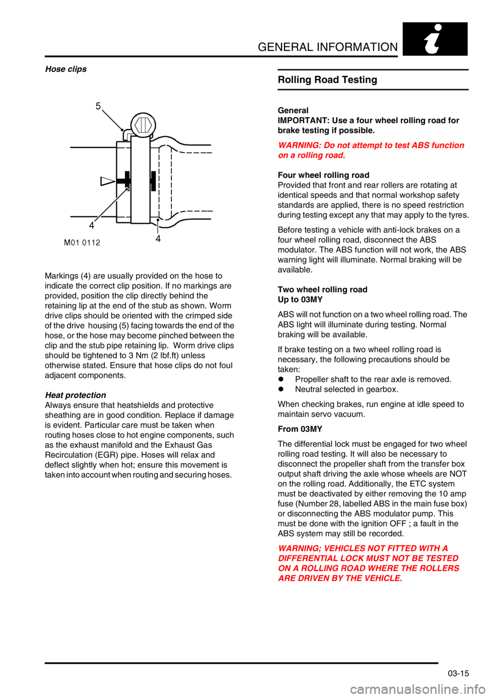
Hose clips
Markings (4) are usually provided on the hose to
indicate the correct clip position. If no markings are
provided, position the clip directly behind the
retaining lip at the end of the stub as shown. Worm
drive clips should be oriented with the crimped side
of the drive housing (5) facing towards the end of the
hose, or the hose may become pinched between the
clip and the stub pipe retaining lip. Worm drive clips
should be tightened to 3 Nm (2 lbf.ft) unless
otherwise stated. Ensure that hose clips do not foul
adjacent components.
Heat protection
Always ensure that heatshields and protective
sheathing are in good condition. Replace if damage
is evident. Particular care must be taken when
routing hoses close to hot engine components, such
as the exhaust manifold and the Exhaust Gas
Recirculation (EGR) pipe. Hoses will relax and
deflect slightly when hot; ensure this movement is
taken into account when routing and securing hoses.
Rolling Road Testing
General
IMPORTANT: Use a four wheel rolling road for
brake testing if possible.
WARNING: Do not attempt to test ABS function
on a rolling road.
Four wheel rolling road
Provided that front and rear rollers are rotating at
identical speeds and that normal workshop safety
standards are applied, there is no speed restriction
during testing except any that may apply to the tyres.
Before testing a vehicle with anti-lock brakes on a
four wheel rolling road, disconnect the ABS
modulator. The ABS function will not work, the ABS
warning light will illuminate. Normal braking will be
available.
Two wheel rolling road
Up to 03MY
ABS will not function on a two wheel rolling road. The
ABS light will illuminate during testing. Normal
braking will be available.
If brake testing on a two wheel rolling road is
necessary, the following precautions should be
taken:
lPropeller shaft to the rear axle is removed.
lNeutral selected in gearbox.
When checking brakes, run engine at idle speed to
maintain servo vacuum.
From 03MY
The differential lock must be engaged for two wheel
rolling road testing. It will also be necessary to
disconnect the propeller shaft from the transfer box
output shaft driving the axle whose wheels are NOT
on the rolling road. Additionally, the ETC system
must be deactivated by either removing the 10 amp
fuse (Number 28, labelled ABS in the main fuse box)
or disconnecting the ABS modulator pump. This
must be done with the ignition OFF ; a fault in the
ABS system may still be recorded.
WARNING; VEHICLES NOT FITTED WITH A
DIFFERENTIAL LOCK MUST NOT BE TESTED
ON A ROLLING ROAD WHERE THE ROLLERS
ARE DRIVEN BY THE VEHICLE.
Page 51 of 1672
GENERAL INFORMATION
03-16
Fuel Handling Precautions
Fuel vapour is highly flammable and in confined
spaces is also explosive and toxic. The vapour is
heavier than air and will always fall to the lowest
level. The vapour can be easily distributed
throughout a workshop by air currents;
consequently, even a small spillage of fuel is
potentially very dangerous.
The following information provides basic precautions
which must be observed if fuel is to be handled
safely. It also outlines other areas of risk which must
not be ignored. This information is issued for basic
guidance only, if in doubt consult your local Fire
Officer.
General
Always have a fire extinguisher containing FOAM,
CO
2, GAS or POWDER close at hand when handling
or draining fuel or when dismantling fuel systems.
Fire extinguishers should also be located in areas
where fuel containers are stored.
Always disconnect the vehicle battery before
carrying out dismantling or draining work on a fuel
system.
Whenever fuel is being handled, drained or stored, or
when fuel systems are being dismantled, all forms of
ignition must be extinguished or removed; any
leadlamps must be flameproof and kept clear of
spillage.
WARNING: No one should be permitted to repair
components associated with fuel without first
having specialist training.
WARNING: Do not remove fuel system
components while the vehicle is over a pit.
Fuel tank draining
Fuel tank draining should be carried out in
accordance with the procedure outlined in the FUEL
DELIVERY section of this manual and observing the
following precautions.
WARNING: Fuel must not be extracted or drained
from any vehicle while it is over a pit. Extraction
or draining of fuel must be carried out in a well
ventilated area.
The capacity of containers must be more than
adequate for the amount of fuel to be extracted or
drained. The container should be clearly marked
with its contents and placed in a safe storage
area which meets the requirements of local
authority regulations.Fuel tank removal
When the fuel line is secured to the fuel tank outlet by
a spring steel clip, the clip must be released before
the fuel line is disconnected or the fuel tank is
removed. This procedure will avoid the possibility of
fumes in the fuel tank being ignited when the clip is
released.
As an added precaution, fuel tanks should have a
'FUEL VAPOUR' warning label attached to them as
soon as they are removed from the vehicle.
Fuel tank repairs - plastic tank
No attempt should be made to repair a plastic fuel
tank. If the structure of the tank is damaged, a new
tank must be fitted.
Body repairs
Plastic fuel pipes are particularly susceptible to heat,
even at relatively low temperature, and can be
melted by heat conducted from some distance away.
When body repairs involve the use of heat, all fuel
pipes which run in the vicinity of the repair area must
be removed, and the tank outlet plugged.
WARNING: If welding is to be carried out in the
vicinity of the fuel tank, the fuel system must be
drained and the tank removed before welding
commences.
Page 52 of 1672
GENERAL INFORMATION
03-17
Electrical Precautions
General
The following guidelines are intended to ensure the
safety of the operator while preventing damage to the
electrical and electronic components fitted to the
vehicle. Where necessary, specific precautions are
detailed in the individual procedures of this manual.
Equipment
Prior to commencing any test procedure on the
vehicle ensure that the relevant test equipment is
working correctly and any harness or connectors are
in good condition. It is particularly important to check
the condition of the lead and plugs of mains operated
equipment.
Polarity
Never reverse connect the vehicle battery and
always ensure the correct polarity when connecting
test equipment.
High voltage circuits
Whenever disconnecting live ht circuits always use
insulated pliers and never allow the open end of the
ht lead to contact other components, particularly
ECU's. Exercise caution when measuring the voltage
on the coil terminals while the engine is running, high
voltage spikes can occur on these terminals.
Connectors and harnesses
The engine compartment of a vehicle is a particularly
hostile environment for electrical components and
connectors:
lAlways ensure electrically related items are dry
and oil free before disconnecting and
connecting test equipment.
lEnsure disconnected multiplugs and sensors
are protected from being contaminated with oil,
coolant or other solutions. Contamination could
impair performance or result in catastrophic
failure.
lNever force connectors apart using tools to
prise apart or by pulling on the wiring harness.
lAlways ensure locking tabs are disengaged
before disconnection, and match orientation to
enable correct reconnection.
lEnsure that any protection (covers, insulation
etc.) is replaced if disturbed.Having confirmed a component to be faulty:
lSwitch off the ignition and disconnect the
battery.
lRemove the component and support the
disconnected harness.
lWhen replacing the component keep oily hands
away from electrical connection areas and push
connectors home until any locking tabs fully
engage.
Battery disconnection
Before disconnecting the battery, disable the alarm
system and switch off all electrical equipment. If the
radio is to be serviced, ensure the security code has
been deactivated.
CAUTION: To prevent damage to electrical
components, always disconnect the battery
when working on the vehicle's electrical system.
The ground lead must be disconnected first and
reconnected last.
CAUTION: Always ensure that battery leads are
routed correctly and are not close to any
potential chafing points.
Battery charging
Only recharge the battery with it removed from the
vehicle. Always ensure any battery charging area is
well ventilated and that every precaution is taken to
avoid naked flames and sparks.
Ignition system safety precautions
The vehicle's ignition system produces high voltage
and the following precautions should be observed
before carrying out any work on the system.
WARNING: Before commencing work on an
ignition system, ensure all high tension
terminals, adapters and diagnostic equipment
are adequately insulated and shielded to prevent
accidental personal contacts and minimise the
risk of shock. Wearers of surgically implanted
pacemaker devices should not be in close
proximity of ignition circuits or diagnostic
equipment.
Disciplines
Switch off the ignition prior to making any connection
or disconnection in the system to prevent electrical
surges caused by disconnecting 'live' connections
damaging electronic components.
Ensure hands and work surfaces are clean and free
of grease, swarf, etc. Grease collects dirt which can
cause electrical tracking (short-circuits) or high-
resistance contacts.
When handling printed circuit boards, treat with care
and hold by the edges only; note that some electronic
components are susceptible to body static.
Page 54 of 1672
GENERAL INFORMATION
03-19
WARNING: Do not use rear facing child seats in
the front passenger seat if the vehicle is fitted
with a passenger airbag.
WARNING: It is imperative that before any work
is undertaken on the SRS system the appropriate
information is read thoroughly.
WARNING: Replace the airbag every 10 years.
Do not install used SRS parts from another car.
When repairing an SRS system, always use
approved new parts.
Carefully inspect the airbag module before
installing it. Do not install an airbag module that
shows signs of being dropped or improperly
handled, such as dents, cracks or deformation.
Do not try to disassemble or tamper with the
airbag module.
Special bolts are necessary for installing the
airbag module. Do not use other bolts.
Preliminary procedures
The SRS system uses energy reserve capacitors
that keep the system active in the event of electrical
supply failure under crash conditions. It is necessary
to allow the capacitors sufficient time to discharge in
order to avoid the risk of accidental deployment.
Always remove the ignition key from the starter
switch, disconnect the vehicle battery and wait 10
minutes before commencing work on the SRS
system.
Carefully inspect any SRS component before
installation. Do not install any SRS component that
shows signs of damage such as dents, cracks or
deformity.Component handling
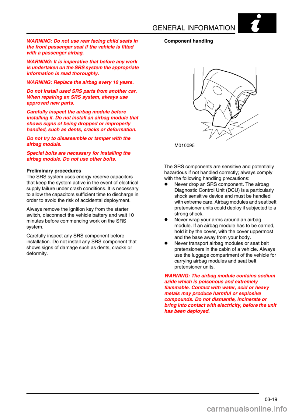
The SRS components are sensitive and potentially
hazardous if not handled correctly; always comply
with the following handling precautions:
lNever drop an SRS component. The airbag
Diagnostic Control Unit (DCU) is a particularly
shock sensitive device and must be handled
with extreme care. Airbag modules and seat belt
pretensioner units could deploy if subjected to a
strong shock.
lNever wrap your arms around an airbag
module. If an airbag module has to be carried,
hold it by the cover, with the cover uppermost
and the base away from your body.
lNever transport airbag modules or seat belt
pretensioners in the cabin of a vehicle. Always
use the luggage compartment of the vehicle for
carrying airbag modules and seat belt
pretensioner units.
WARNING: The airbag module contains sodium
azide which is poisonous and extremely
flammable. Contact with water, acid or heavy
metals may produce harmful or explosive
compounds. Do not dismantle, incinerate or
bring into contact with electricity, before the unit
has been deployed.