steering LAND ROVER FREELANDER 2001 User Guide
[x] Cancel search | Manufacturer: LAND ROVER, Model Year: 2001, Model line: FREELANDER, Model: LAND ROVER FREELANDER 2001Pages: 1007, PDF Size: 23.47 MB
Page 90 of 1007
GENERAL DATA
04-27
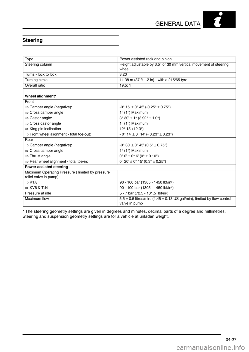
Steering
* The steering geometry settings are given in degrees and minutes, decimal parts of a degree and millimetres.
Steering and suspension geometry settings are for a vehicle at unladen weight.
Type Power assisted rack and pinion
Steering column Height adjustable by 3.5° or 30 mm vertical movement of steering
wheel
Turns - lock to lock 3.20
Turning circle: 11.38 m (37 ft 1.2 in) - with a 215/65 tyre
Overall ratio 19.5: 1
Wheel alignment*
Front
⇒ Camber angle (negative): -0° 15' ± 0° 45' (-0.25° ± 0.75°)
⇒ Cross camber angle 1° (1°) Maximum
⇒ Castor angle: 3° 30' ± 1° (3.92° ± 1.0°)
⇒ Cross castor angle 1° (1°) Maximum
⇒ King pin inclination 12° 18' (12.3°)
⇒ Front wheel alignment - total toe-out: - 0° 14' ± 0° 14' (- 0.23° ± 0.23°)
Rear
⇒ Camber angle (negative): -0° 30' ± 0° 45' (0.5° ± 0.75°)
⇒ Cross camber angle 1° (1°) Maximum
⇒ Thrust angle: 0° 0' ± 0° 6' (0° ± 0.10°)
⇒ Rear wheel alignment - total toe-in: 0° 20' ± 0° 15' (0.3° ± 0.25°)
Power assisted steering
Maximum Operating Pressure ( limited by pressure
relief valve in pump):
⇒ K1.8 90 - 100 bar (1305 - 1450 lbf/in
2)
⇒ KV6 & Td4 90 - 100 bar (1305 - 1450 lbf/in
2)
Pressure at idle 5 - 7 bar (72.5 - 101.5 lbf/in
2)
Maximum flow 5.5 ± 0.5 litres/min. (1.45 ± 0.13 US gal/min), limited by flow control
valve in pump
Page 101 of 1007
IDENTIFICATION NUMBERS
05-2
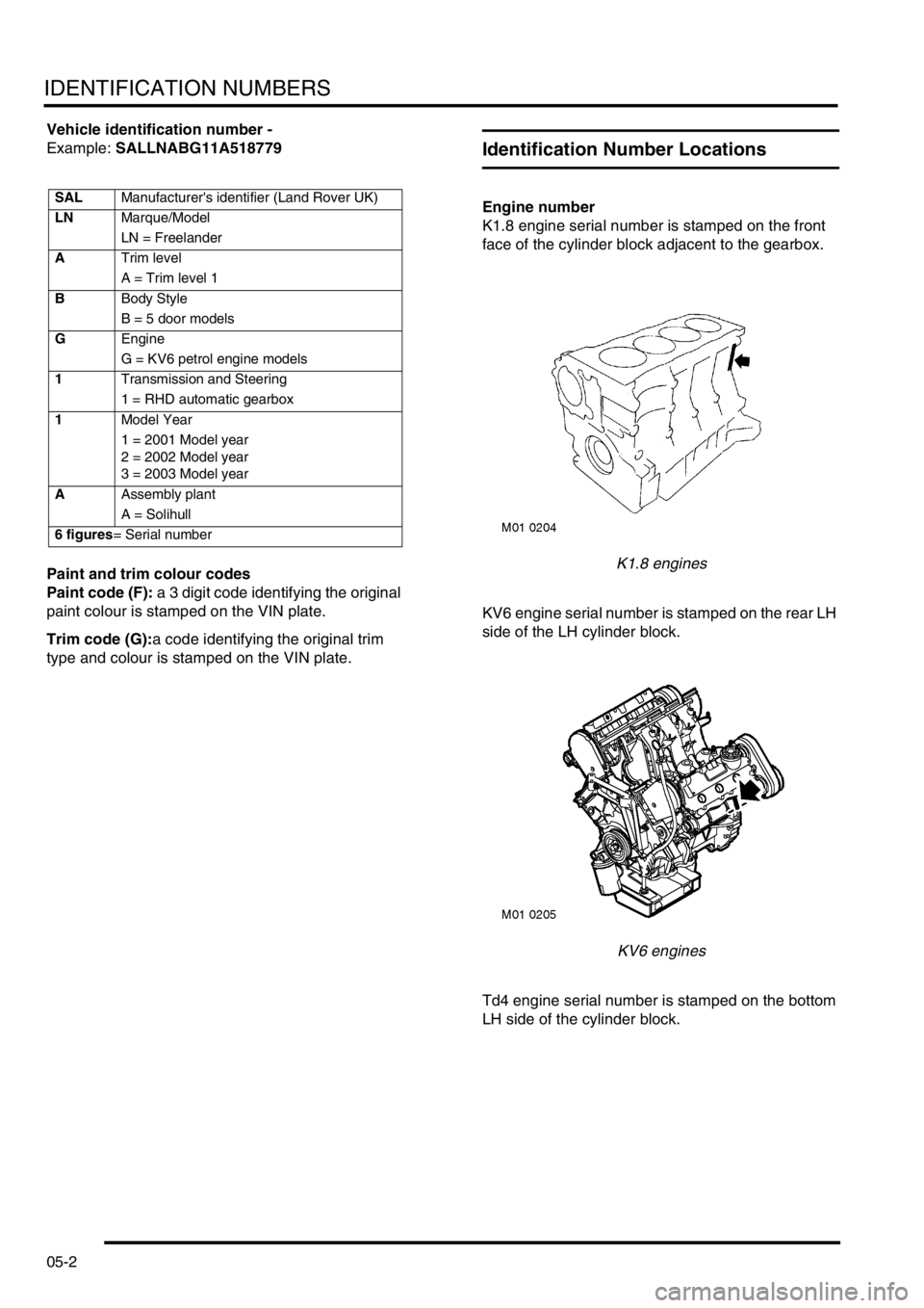
Vehicle identification number -
Example: SALLNABG11A518779
Paint and trim colour codes
Paint code (F): a 3 digit code identifying the original
paint colour is stamped on the VIN plate.
Trim code (G):a code identifying the original trim
type and colour is stamped on the VIN plate.
Identification Number Locations
Engine number
K1.8 engine serial number is stamped on the front
face of the cylinder block adjacent to the gearbox.
K1.8 engines
KV6 engine serial number is stamped on the rear LH
side of the LH cylinder block.
KV6 engines
Td4 engine serial number is stamped on the bottom
LH side of the cylinder block.SALManufacturer's identifier (Land Rover UK)
LNMarque/Model
LN = Freelander
ATrim level
A = Trim level 1
BBody Style
B = 5 door models
GEngine
G = KV6 petrol engine models
1Transmission and Steering
1 = RHD automatic gearbox
1Model Year
1 = 2001 Model year
2 = 2002 Model year
3 = 2003 Model year
AAssembly plant
A = Solihull
6 figures= Serial number
Page 128 of 1007
TORQUE WRENCH SETTINGS
06-25
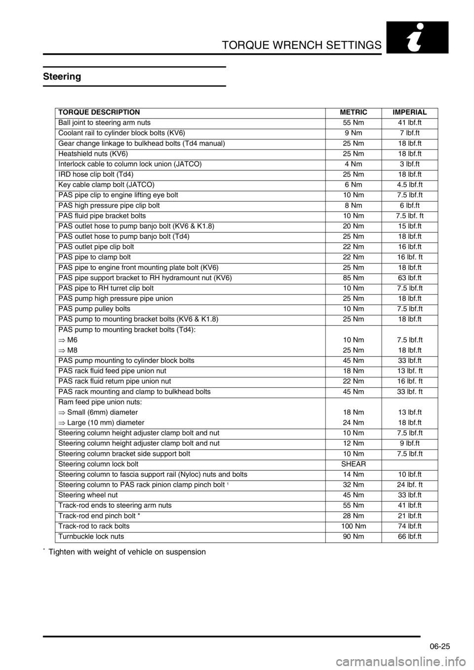
Steering
* Tighten with weight of vehicle on suspension
TORQUE DESCRIPTION METRIC IMPERIAL
Ball joint to steering arm nuts 55 Nm 41 lbf.ft
Coolant rail to cylinder block bolts (KV6) 9 Nm 7 lbf.ft
Gear change linkage to bulkhead bolts (Td4 manual) 25 Nm 18 lbf.ft
Heatshield nuts (KV6) 25 Nm 18 lbf.ft
Interlock cable to column lock union (JATCO) 4 Nm 3 lbf.ft
IRD hose clip bolt (Td4) 25 Nm 18 lbf.ft
Key cable clamp bolt (JATCO) 6 Nm 4.5 lbf.ft
PAS pipe clip to engine lifting eye bolt 10 Nm 7.5 lbf.ft
PAS high pressure pipe clip bolt 8 Nm 6 lbf.ft
PAS fluid pipe bracket bolts 10 Nm 7.5 lbf. ft
PAS outlet hose to pump banjo bolt (KV6 & K1.8) 20 Nm 15 lbf.ft
PAS outlet hose to pump banjo bolt (Td4) 25 Nm 18 lbf.ft
PAS outlet pipe clip bolt 22 Nm 16 lbf.ft
PAS pipe to clamp bolt 22 Nm 16 lbf. ft
PAS pipe to engine front mounting plate bolt (KV6) 25 Nm 18 lbf.ft
PAS pipe support bracket to RH hydramount nut (KV6) 85 Nm 63 lbf.ft
PAS pipe to RH turret clip bolt 10 Nm 7.5 lbf.ft
PAS pump high pressure pipe union 25 Nm 18 lbf.ft
PAS pump pulley bolts 10 Nm 7.5 lbf.ft
PAS pump to mounting bracket bolts (KV6 & K1.8) 25 Nm 18 lbf.ft
PAS pump to mounting bracket bolts (Td4):
⇒ M610 Nm 7.5 lbf.ft
⇒ M825 Nm 18 lbf.ft
PAS pump mounting to cylinder block bolts 45 Nm 33 lbf.ft
PAS rack fluid feed pipe union nut 18 Nm 13 lbf. ft
PAS rack fluid return pipe union nut 22 Nm 16 lbf. ft
PAS rack mounting and clamp to bulkhead bolts 45 Nm 33 lbf. ft
Ram feed pipe union nuts:
⇒ Small (6mm) diameter 18 Nm 13 lbf.ft
⇒ Large (10 mm) diameter 24 Nm 18 lbf.ft
Steering column height adjuster clamp bolt and nut 10 Nm 7.5 lbf.ft
Steering column height adjuster clamp bolt and nut 12 Nm 9 lbf.ft
Steering column bracket side support bolt 10 Nm 7.5 lbf.ft
Steering column lock bolt SHEAR
Steering column to fascia support rail (Nyloc) nuts and bolts 14 Nm 10 lbf.ft
Steering column to PAS rack pinion clamp pinch bolt
132 Nm 24 lbf. ft
Steering wheel nut 45 Nm 33 lbf.ft
Track-rod ends to steering arm nuts 55 Nm 41 lbf.ft
Track-rod end pinch bolt * 28 Nm 21 lbf.ft
Track-rod to rack bolts 100 Nm 74 lbf.ft
Turnbuckle lock nuts 90 Nm 66 lbf.ft
Page 132 of 1007
TORQUE WRENCH SETTINGS
06-29
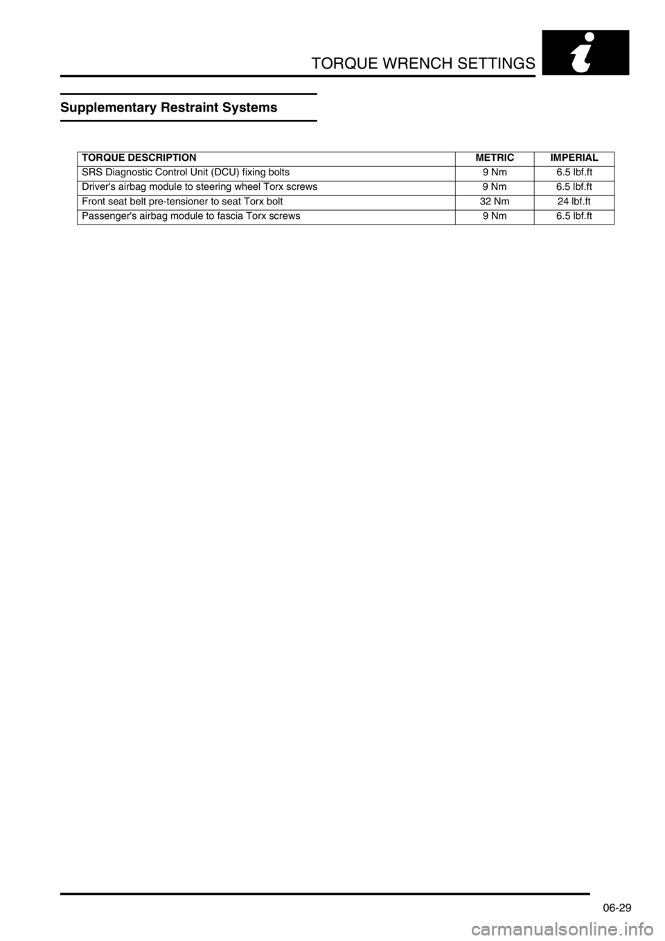
Supplementary Restraint Systems
TORQUE DESCRIPTION METRIC IMPERIAL
SRS Diagnostic Control Unit (DCU) fixing bolts 9 Nm 6.5 lbf.ft
Driver's airbag module to steering wheel Torx screws 9 Nm 6.5 lbf.ft
Front seat belt pre-tensioner to seat Torx bolt 32 Nm 24 lbf.ft
Passenger's airbag module to fascia Torx screws 9 Nm 6.5 lbf.ft
Page 133 of 1007
TORQUE WRENCH SETTINGS
06-30
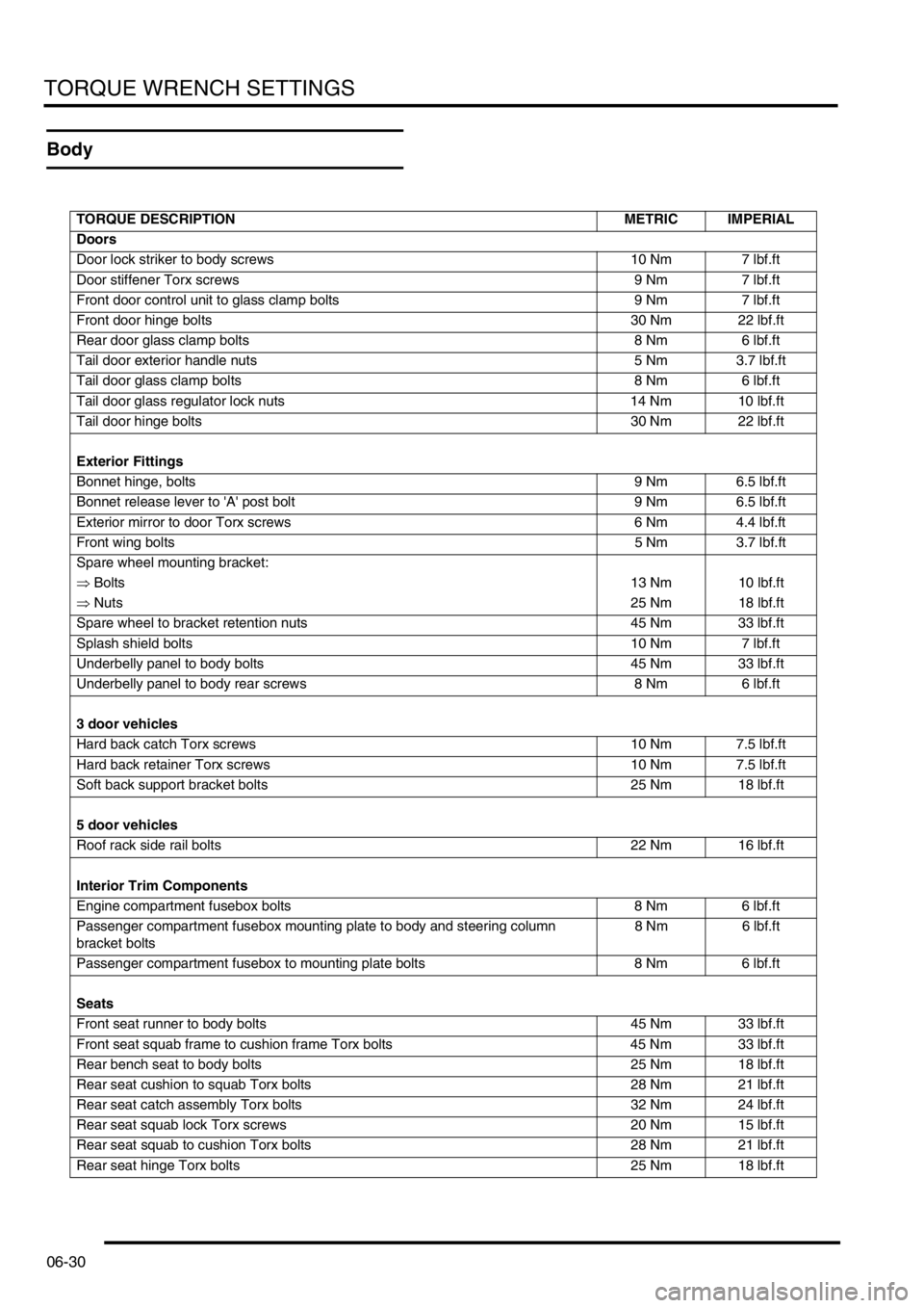
Body
TORQUE DESCRIPTION METRIC IMPERIAL
Doors
Door lock striker to body screws 10 Nm 7 lbf.ft
Door stiffener Torx screws 9 Nm 7 lbf.ft
Front door control unit to glass clamp bolts 9 Nm 7 lbf.ft
Front door hinge bolts 30 Nm 22 lbf.ft
Rear door glass clamp bolts 8 Nm 6 lbf.ft
Tail door exterior handle nuts 5 Nm 3.7 lbf.ft
Tail door glass clamp bolts 8 Nm 6 lbf.ft
Tail door glass regulator lock nuts 14 Nm 10 lbf.ft
Tail door hinge bolts 30 Nm 22 lbf.ft
Exterior Fittings
Bonnet hinge, bolts 9 Nm 6.5 lbf.ft
Bonnet release lever to 'A' post bolt 9 Nm 6.5 lbf.ft
Exterior mirror to door Torx screws 6 Nm 4.4 lbf.ft
Front wing bolts5 Nm 3.7 lbf.ft
Spare wheel mounting bracket:
⇒ Bolts13 Nm 10 lbf.ft
⇒ Nuts25 Nm 18 lbf.ft
Spare wheel to bracket retention nuts 45 Nm 33 lbf.ft
Splash shield bolts 10 Nm 7 lbf.ft
Underbelly panel to body bolts 45 Nm 33 lbf.ft
Underbelly panel to body rear screws 8 Nm 6 lbf.ft
3 door vehicles
Hard back catch Torx screws 10 Nm 7.5 lbf.ft
Hard back retainer Torx screws 10 Nm 7.5 lbf.ft
Soft back support bracket bolts 25 Nm 18 lbf.ft
5 door vehicles
Roof rack side rail bolts 22 Nm 16 lbf.ft
Interior Trim Components
Engine compartment fusebox bolts 8 Nm 6 lbf.ft
Passenger compartment fusebox mounting plate to body and steering column
bracket bolts8 Nm 6 lbf.ft
Passenger compartment fusebox to mounting plate bolts 8 Nm 6 lbf.ft
Seats
Front seat runner to body bolts 45 Nm 33 lbf.ft
Front seat squab frame to cushion frame Torx bolts 45 Nm 33 lbf.ft
Rear bench seat to body bolts 25 Nm 18 lbf.ft
Rear seat cushion to squab Torx bolts 28 Nm 21 lbf.ft
Rear seat catch assembly Torx bolts 32 Nm 24 lbf.ft
Rear seat squab lock Torx screws 20 Nm 15 lbf.ft
Rear seat squab to cushion Torx bolts 28 Nm 21 lbf.ft
Rear seat hinge Torx bolts 25 Nm 18 lbf.ft
Page 140 of 1007
LIFTING AND TOWING
08-1
LIFTING AND TOWING
Jacking
The following instructions must be carried out before
raising the vehicle off the ground:
lUse a solid level surface.
lApply parking brake.
lSelect 1st. gear in main gearbox and ensure
HDC is not selected.
CAUTION: To avoid damage to under body
components of the vehicle, adhere to the
following jacking procedures:
DO NOT POSITION JACKS OR AXLE STANDS
UNDER THE FOLLOWING COMPONENTS:
lBumpers
lBrake or Fuel lines
lExhaust pipe
lSuspension components
lSteering rack and linkages
lFuel tank
lEngine sump
lGearbox
lIRD unit
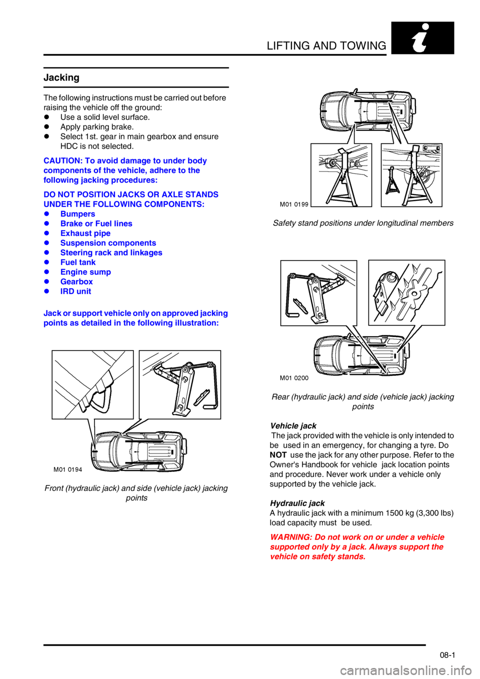
Jack or support vehicle only on approved jacking
points as detailed in the following illustration:
Front (hydraulic jack) and side (vehicle jack) jacking
pointsSafety stand positions under longitudinal members
Rear (hydraulic jack) and side (vehicle jack) jacking
points
Vehicle jack
The jack provided with the vehicle is only intended to
be used in an emergency, for changing a tyre. Do
NOT use the jack for any other purpose. Refer to the
Owner's Handbook for vehicle jack location points
and procedure. Never work under a vehicle only
supported by the vehicle jack.
Hydraulic jack
A hydraulic jack with a minimum 1500 kg (3,300 lbs)
load capacity must be used.
WARNING: Do not work on or under a vehicle
supported only by a jack. Always support the
vehicle on safety stands.
Page 141 of 1007
LIFTING AND TOWING
08-2
Raising the front of a vehicle
Position the cup of the hydraulic arm under the
centre of the front body crossmember assembly.
Use jack to raise front road wheels to enable safety
stands to be installed under the front end of each
longitudinal member.
Carefully lower jack until vehicle sits securely on
safety stands.
Before working on the underside of a vehicle re-
check the stability of the vehicle on the stands.
Use the reverse procedure when removing a vehicle
from stands.
NOTE: For some repair operations it may be
necessary to use a jack to support the engine under
the sump. In this case, a block of wood should be
used on the jack to protect the sump.
Raising the rear of a vehicle
Position cup of hydraulic arm under the centre of the
rear subframe crossmember at the position
identified by the embossed arrows.
Use jack to raise rear road wheels to enable safety
stands to be installed under the rear ends of the
body longitudinal members.
Carefully lower jack until vehicle sits securely on
safety stands.
Before working on the underside of a vehicle, re-
check the stability of the vehicle on the stands.
Use the reverse procedure when removing a vehicle
from stands.
Wheel-free lift
Locate the lifting pads under the ends of the body
longitudinal members. Raise the ramp to support the
weight of the vehicle, ensure the vehicle is secure on
the lifting pads, then raise the ramp to the required
height.
Towing
General
The vehicle has permanent four wheel drive. The
following instructions must be adhered to:
Towing the vehicle on all four wheels with driver
operating steering and brakes
lTurn ignition key to position '1' to release
steering lock and then to position 'II' to enable
the brake lights, wipers and direction indicators
to be operated, if necessary.
l Select neutral in gearbox and ensure HDC (hill
descent control) is deselected.
lSecure tow rope, chain or cable to towing eye.
lRelease the parking brake.
CAUTION: The brake servo and power assisted
steering system will not be functional without the
engine running. Greater pedal pressure will be
required to apply the brakes and the steering
system will require greater effort to turn the front
road wheels. The vehicle tow connection should
only be used under normal road conditions,
'snatch' recovery should be avoided.
Suspended tow by breakdown vehicle
Mark propeller shaft drive flanges and mating flanges
with identification lines to enable the propeller shaft
to be refitted in its original position.
Remove the propeller shaft fixings then remove the
shaft from the vehicle.
CAUTION: To prevent vehicle damage, rear
propeller shaft MUST BE removed.
Page 142 of 1007
LIFTING AND TOWING
08-3
If the front of the vehicle is to be trailed, turn ignition
key to position 'I' to release steering lock.
WARNING: Do not turn the starter switch to
position '0' or remove the ignition key while the
vehicle is being towed.
CAUTION: If it is considered unsafe to turn the
starter switch to position '1' due to accident
damage or an electrical fault; disconnect the
battery before turning the ignition switch.
CAUTION: The steering wheel and/or linkage
must be secured in a straight ahead position. DO
NOT use the steering lock mechanism for this
purpose.
CAUTION: Under no circumstances should the
vehicle be towed or recovered by means of
lashing to the rear subframe. Serious damage to
the subframe and body could result.
CAUTION: Only use the rear towing eye for
towing another vehicle.
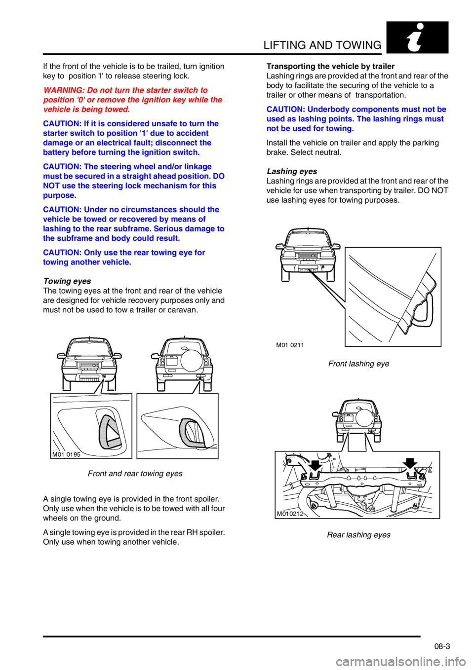
Towing eyes
The towing eyes at the front and rear of the vehicle
are designed for vehicle recovery purposes only and
must not be used to tow a trailer or caravan.
Front and rear towing eyes
A single towing eye is provided in the front spoiler.
Only use when the vehicle is to be towed with all four
wheels on the ground.
A single towing eye is provided in the rear RH spoiler.
Only use when towing another vehicle.Transporting the vehicle by trailer
Lashing rings are provided at the front and rear of the
body to facilitate the securing of the vehicle to a
trailer or other means of transportation.
CAUTION: Underbody components must not be
used as lashing points. The lashing rings must
not be used for towing.
Install the vehicle on trailer and apply the parking
brake. Select neutral.
Lashing eyes
Lashing rings are provided at the front and rear of the
vehicle for use when transporting by trailer. DO NOT
use lashing eyes for towing purposes.
Front lashing eye
Rear lashing eyes
Page 144 of 1007
CAPACITIES, FLUIDS, LUBRICANTS AND SEALANTS
09-1
CAPACITIES, FLUIDS, LUBRICANTS AND SEALANTS
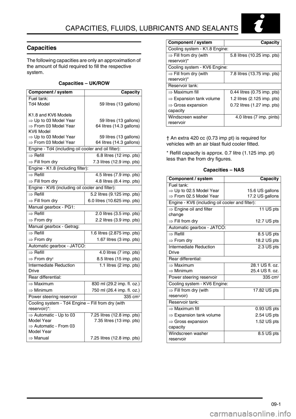
Capacities
The following capacities are only an approximation of
the amount of fluid required to fill the respective
system.
Capacities – UK/ROW
† An extra 420 cc (0.73 imp pt) is required for
vehicles with an air blast fluid cooler fitted.
* Refill capacity is approx. 0.7 litre (1.125 imp. pt)
less than the from dry figures.
Capacities – NAS
Component / system Capacity
Fuel tank:
Td4 Model
K1.8 and KV6 Models
⇒ Up to 03 Model Year
⇒ From 03 Model Year
KV6 Model
⇒ Up to 03 Model Year
⇒ From 03 Model Year59 litres (13 gallons)
59 litres (13 gallons)
64 litres (14.3 gallons)
59 litres (13 gallons)
64 litres (14.3 gallons)
Engine - Td4 (including oil cooler and oil filter):
⇒ Refill 6.8 litres (12 imp. pts)
⇒ Fill from dry 7.3 litres (12.9 imp. pts)
Engine - K1.8 (including filter):
⇒ Refill 4.5 litres (7.9 imp. pts)
⇒ Fill from dry 4.8 litres (8.4 imp. pts)
Engine - KV6 (including oil cooler and filter):
⇒ Refill 5.2 litres (9.125 imp. pts)
⇒ Fill from dry 6.0 litres (10.625 imp. pts)
Manual gearbox - PG1:
⇒ Refill 2.0 litres (3.5 imp. pts)
⇒ From dry 2.2 litres (3.9 imp. pts)
Manual gearbox - Getrag:
⇒ Refill 1.6 litres (2.875 imp. pts)
⇒ From dry 1.67 litres (3 imp. pts)
Automatic gearbox - JATCO:
⇒ Refill 4.0 litres (7 imp. pts)
⇒ From dry
†8.5 litres (15 imp. pts)
Intermediate Reduction
Drive1.1 litres (2 imp. pts)
Rear differential:
⇒ Maximum 830 ml (29.2 imp. fl. oz.)
⇒ Minimum 750 ml (26.4 imp. fl. oz.)
Power steering reservoir 335 cm
3
Cooling system - Td4 Engine – Fill from dry (with
reservoir)*:
⇒ Automatic - Up to 03
Model Year
⇒ Automatic - From 03
Model Year7.25 litres (12.8 imp. pts)
7.35 litres (13 imp. pts)
⇒ Manual 7.25 litres (12.8 imp. pts)
Cooling system - K1.8 Engine:
⇒ Fill from dry (with
reservoir)*5.8 litres (10.25 imp. pts)
Cooling system - KV6 Engine:
⇒ Fill from dry (with
reservoir)*7.8 litres (13.75 imp. pts)
Reservoir tank:
⇒ Maximum fill 0.44 litres (0.75 imp. pts)
⇒ Expansion tank volume 1.2 litres (2.125 imp. pts)
⇒ Gross expansion
capacity0.72 litres (1.27 imp. pts)
Windscreen washer
reservoir 4.0 litres (7 imp. pints)
Component / system Capacity
Fuel tank:
⇒ Up to 02.5 Model Year
⇒ From 02.5 Model Year15.6 US gallons
17.2 US gallons
Engine - KV6 (including oil cooler and filter):
⇒ Engine oil and filter
change11 US pts
⇒ Fill from dry 12.7 US pts
Automatic gearbox - JATCO:
⇒ Refill 8.5 US pts
⇒ From dry 18.2 US pts
Intermediate Reduction
Drive2.3 US pts
Rear differential:
⇒ Maximum
⇒ Minimum28.1 US fl. oz.
25.4 US fl. oz.
Power steering reservoir 335 cm
3
Cooling system - KV6 Engine:
⇒ Fill from dry (with
reservoir)17.82 US pts
Reservoir tank:
⇒ Maximum fill 0.93 US pts
⇒ Expansion tank volume 2.54 US pts
⇒ Gross expansion
capacity1.52 US pts
Windscreen washer
reservoir 8.5 US pts Component / system Capacity
Page 148 of 1007
MAINTENANCE
MAINTENANCE 10-1
MAINTENANCE MAINTENANCE
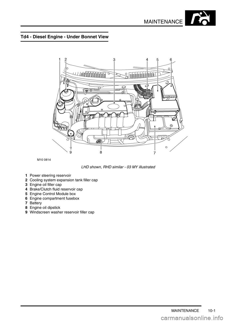
Td4 - Diesel Engine - Under Bonnet View
LHD shown, RHD similar - 03 MY illustrated
1Power steering reservoir
2Cooling system expansion tank filler cap
3Engine oil filler cap
4Brake/Clutch fluid reservoir cap
5Engine Control Module box
6Engine compartment fusebox
7Battery
8Engine oil dipstick
9Windscreen washer reservoir filler cap