seats LAND ROVER FREELANDER 2001 Workshop Manual
[x] Cancel search | Manufacturer: LAND ROVER, Model Year: 2001, Model line: FREELANDER, Model: LAND ROVER FREELANDER 2001Pages: 1007, PDF Size: 23.47 MB
Page 7 of 1007

CONTENTS
4CONTENTS
MAINTENANCE ........................................................................................ 10-1
MAINTENANCE
Td4 - Diesel Engine - Under Bonnet View ...................................................................................... 10-1
K1.8 – Petrol Engine – Under Bonnet View .................................................................................... 10-2
KV6 – Petrol Engine – Under Bonnet View .................................................................................... 10-3
Seats and Seat Belts ...................................................................................................................... 10-4
Lamps, Horns and Warning Indicators ........................................................................................... 10-4
Wipers and Washers ...................................................................................................................... 10-5
Handbrake ...................................................................................................................................... 10-5
Alarm Handset Battery.................................................................................................................... 10-6
Road Wheels .................................................................................................................................. 10-6
Tyres ............................................................................................................................................... 10-7
Brake Pads and Calipers ................................................................................................................ 10-7
Brake Fluid...................................................................................................................................... 10-9
Road Wheel Speed Sensors .......................................................................................................... 10-9
Fuel Filter - Petrol ........................................................................................................................... 10-10
Fuel Filter - Diesel........................................................................................................................... 10-10
Fuel Pump and Filter assembly - Diesel - 03 Model Year onwards ................................................ 10-10
Fuel Sedimenter - Diesel - 03 Model Year onwards ....................................................................... 10-10
Door Locks, Hinges, Check Straps and Bonnet Catch ................................................................... 10-11
Anti-freeze ...................................................................................................................................... 10-12
Cooling System and Intercooler...................................................................................................... 10-12
Vent filter - turbocharger boost control solenoid valve - Td4 .......................................................... 10-13
Spark Plugs – K1.8 ......................................................................................................................... 10-13
Spark Plugs – KV6.......................................................................................................................... 10-13
Air Cleaner – Petrol Models ............................................................................................................ 10-13
Ancillary Drive Belt – Td4 ............................................................................................................... 10-14
Ancillary Drive Belt – K1.8 .............................................................................................................. 10-14
Ancillary Drive Belt – KV6 ............................................................................................................... 10-15
Camshaft Timing Belt – K1.8 .......................................................................................................... 10-15
Camshaft Timing Belt – KV6........................................................................................................... 10-16
Brake/Clutch Reservoir ................................................................................................................... 10-16
PAS Fluid Level .............................................................................................................................. 10-17
Intermediate Reduction Drive - Non NAS models .......................................................................... 10-17
Intermediate Reduction Drive - NAS models .................................................................................. 10-18
Manual Gearbox – PG1 .................................................................................................................. 10-18
Manual Gearbox – GETRAG .......................................................................................................... 10-19
Automatic Gearbox – JATCO ......................................................................................................... 10-19
Rear Axle ........................................................................................................................................ 10-20
Clutch Pipes and Unions ................................................................................................................ 10-21
Windscreen and Rear Washer Reservoir ....................................................................................... 10-21
Battery ............................................................................................................................................ 10-21
Engine Oil and Filter – Td4 ............................................................................................................. 10-22
Engine Oil and Filter – K1.8 ............................................................................................................ 10-23
Engine Oil and Filter – KV6 ............................................................................................................ 10-24
Fuel Hoses and Pipes..................................................................................................................... 10-25
Brake Hoses and Pipes ................................................................................................................. 10-26
Check Exhaust System................................................................................................................... 10-26
Suspension ..................................................................................................................................... 10-27
Steering ......................................................................................................................................... 10-28
Road Test ....................................................................................................................................... 10-28
Endorse Service Record ................................................................................................................. 10-30
Report any Unusual Features ......................................................................................................... 10-30
Page 17 of 1007

CONTENTS
14 CONTENTS
INTERIOR TRIM COMPONENTS ............................................................. 76-3-1
REPAIRS
Sun visor ......................................................................................................................................... 76-3-1
Trim casing - rear quarter - lower - 3 door ...................................................................................... 76-3-1
Trim casing - rear quarter - lower - 5 door ...................................................................................... 76-3-2
Trim casing - rear quarter - upper - 3 door ..................................................................................... 76-3-3
Trim casing - rear quarter - upper - 5 door ..................................................................................... 76-3-4
Trim finisher - 'A' post - upper - renew ............................................................................................ 76-3-5
Trim finisher - 'B/C' post - upper - renew ........................................................................................ 76-3-6
Trim finisher - 'B' post - lower - 5 door ............................................................................................ 76-3-7
Trim casing - body side - rear - 3 door............................................................................................ 76-3-8
Console - front - up to 04MY........................................................................................................... 76-3-9
Console assembly - front - from 04MY ........................................................................................... 76-3-11
Console - rear ................................................................................................................................. 76-3-12
Cup holder - fascia - from 04MY ..................................................................................................... 76-3-13
Fascia - up to 04MY........................................................................................................................ 76-3-14
Fascia - from 04MY ........................................................................................................................ 76-3-19
Drink tray assembly - fascia - up to 04MY ...................................................................................... 76-3-23
Stowage box - fascia ...................................................................................................................... 76-3-23
Carpet - luggage compartment ....................................................................................................... 76-3-24
Glove box........................................................................................................................................ 76-3-25
Headlining - 3 door ......................................................................................................................... 76-3-25
Headlining - 5 door ......................................................................................................................... 76-3-27
SCREENS ................................................................................................. 76-4-1
REPAIRS
Windscreen ..................................................................................................................................... 76-4-1
Glass - body side - rear .................................................................................................................. 76-4-3
SEATS ....................................................................................................... 76-5-1
REPAIRS
Front seat ....................................................................................................................................... 76-5-1
Rear seat - LH ............................................................................................................................... 76-5-1
Rear seat - RH ............................................................................................................................... 76-5-2
Cushion & squab - rear seat - bench type - 3 door ........................................................................ 76-5-2
Cover - one piece - front seat cushion ........................................................................................... 76-5-3
Cover - rear seat cushion - RH ..................................................................................................... 76-5-4
Cover - rear seat cushion - LH........................................................................................................ 76-5-6
Cover - cushion - rear single seat - 3 door .................................................................................... 76-5-7
Finisher - seat base - front - each .................................................................................................. 76-5-8
Finisher - cushion side - front seat ................................................................................................. 76-5-9
Manual mechanism - lumbar support - front seat .......................................................................... 76-5-9
Latch - rear squab - RH ................................................................................................................. 76-5-11
Latch - rear squab - LH ................................................................................................................... 76-5-11
Cover - squab - front seat .............................................................................................................. 76-5-12
Cover - squab - rear seat - side - LH .............................................................................................. 76-5-13
Cover - squab - rear seat - RH ...................................................................................................... 76-5-14
Cover - squab - rear single seat - 3 door ....................................................................................... 76-5-16
Page 52 of 1007
GENERAL INFORMATION
03-21
It should be noted that these precautions are not
restricted to operations performed when servicing
the SRS system, the same care should be exercised
when working on ancillary systems and components
located in the vicinity of SRS components; these
include but are not limited to:
lSteering system – steering wheel airbag,
rotary coupler.
lFront fascia – passenger front airbag (where
fitted); SRS DCU behind centre console, on
transmission tunnel under the HeVAC system.
lFront seats – seat belt pre-tensioners, integral
with seat belt buckle assembly.
lElectrical system – SRS harnesses, link leads
and connectors.
Making the SRS system safe
Before working on or in the vicinity of SRS
components, ensure the system is rendered safe by
performing the following procedures:
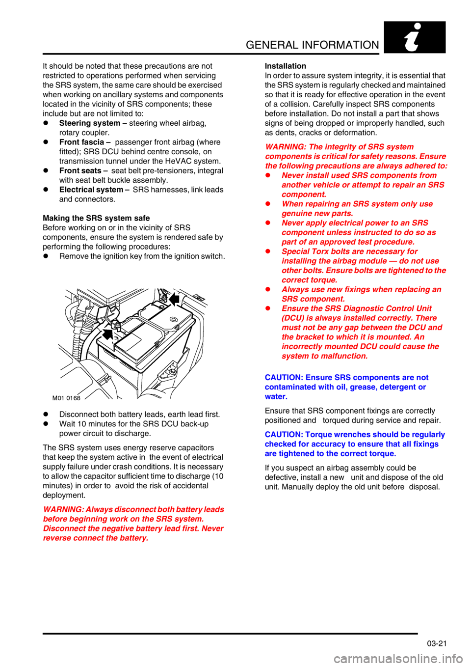
lRemove the ignition key from the ignition switch.
lDisconnect both battery leads, earth lead first.
lWait 10 minutes for the SRS DCU back-up
power circuit to discharge.
The SRS system uses energy reserve capacitors
that keep the system active in the event of electrical
supply failure under crash conditions. It is necessary
to allow the capacitor sufficient time to discharge (10
minutes) in order to avoid the risk of accidental
deployment.
WARNING: Always disconnect both battery leads
before beginning work on the SRS system.
Disconnect the negative battery lead first. Never
reverse connect the battery.Installation
In order to assure system integrity, it is essential that
the SRS system is regularly checked and maintained
so that it is ready for effective operation in the event
of a collision. Carefully inspect SRS components
before installation. Do not install a part that shows
signs of being dropped or improperly handled, such
as dents, cracks or deformation.
WARNING: The integrity of SRS system
components is critical for safety reasons. Ensure
the following precautions are always adhered to:
lNever install used SRS components from
another vehicle or attempt to repair an SRS
component.
lWhen repairing an SRS system only use
genuine new parts.
lNever apply electrical power to an SRS
component unless instructed to do so as
part of an approved test procedure.
lSpecial Torx bolts are necessary for
installing the airbag module — do not use
other bolts. Ensure bolts are tightened to the
correct torque.
lAlways use new fixings when replacing an
SRS component.
lEnsure the SRS Diagnostic Control Unit
(DCU) is always installed correctly. There
must not be any gap between the DCU and
the bracket to which it is mounted. An
incorrectly mounted DCU could cause the
system to malfunction.
CAUTION: Ensure SRS components are not
contaminated with oil, grease, detergent or
water.
Ensure that SRS component fixings are correctly
positioned and torqued during service and repair.
CAUTION: Torque wrenches should be regularly
checked for accuracy to ensure that all fixings
are tightened to the correct torque.
If you suspect an airbag assembly could be
defective, install a new unit and dispose of the old
unit. Manually deploy the old unit before disposal.
Page 56 of 1007
GENERAL INFORMATION
03-25
Warning Labels
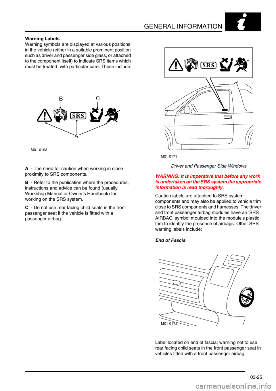
Warning symbols are displayed at various positions
in the vehicle (either in a suitable prominent position
such as driver and passenger side glass, or attached
to the component itself) to indicate SRS items which
must be treated with particular care. These include:
A - The need for caution when working in close
proximity to SRS components.
B - Refer to the publication where the procedures,
instructions and advice can be found (usually
Workshop Manual or Owner's Handbook) for
working on the SRS system.
C - Do not use rear facing child seats in the front
passenger seat if the vehicle is fitted with a
passenger airbag.Driver and Passenger Side Windows
WARNING: It is imperative that before any work
is undertaken on the SRS system the appropriate
information is read thoroughly.
Caution labels are attached to SRS system
components and may also be applied to vehicle trim
close to SRS components and harnesses. The driver
and front passenger airbag modules have an 'SRS
AIRBAG' symbol moulded into the module's plastic
trim to identify the presence of airbags. Other SRS
warning labels include:
End of Fascia
Label located on end of fascia; warning not to use
rear facing child seats in the front passenger seat in
vehicles fitted with a front passenger airbag.
Page 133 of 1007
TORQUE WRENCH SETTINGS
06-30
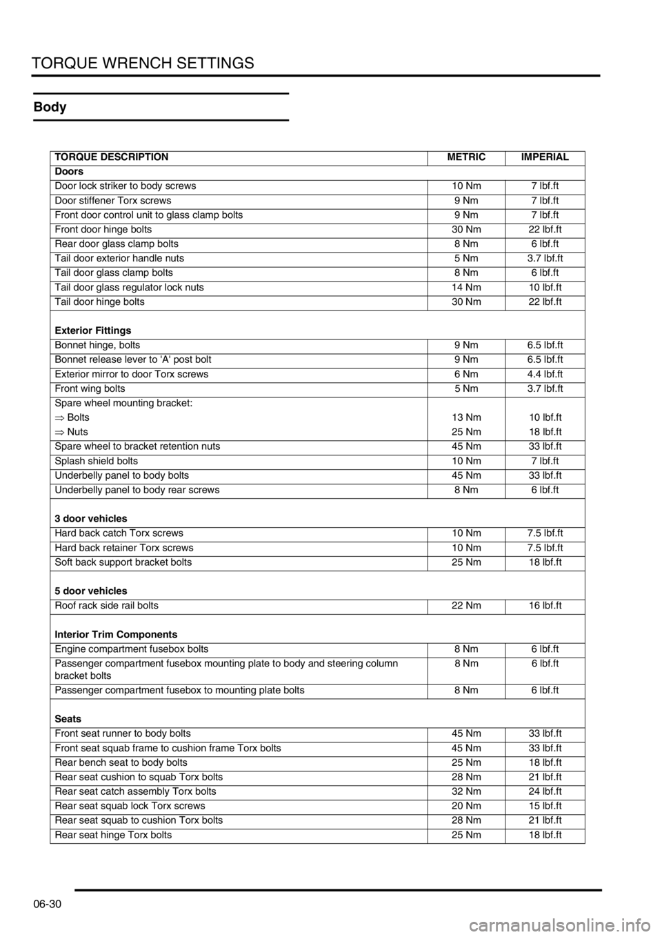
Body
TORQUE DESCRIPTION METRIC IMPERIAL
Doors
Door lock striker to body screws 10 Nm 7 lbf.ft
Door stiffener Torx screws 9 Nm 7 lbf.ft
Front door control unit to glass clamp bolts 9 Nm 7 lbf.ft
Front door hinge bolts 30 Nm 22 lbf.ft
Rear door glass clamp bolts 8 Nm 6 lbf.ft
Tail door exterior handle nuts 5 Nm 3.7 lbf.ft
Tail door glass clamp bolts 8 Nm 6 lbf.ft
Tail door glass regulator lock nuts 14 Nm 10 lbf.ft
Tail door hinge bolts 30 Nm 22 lbf.ft
Exterior Fittings
Bonnet hinge, bolts 9 Nm 6.5 lbf.ft
Bonnet release lever to 'A' post bolt 9 Nm 6.5 lbf.ft
Exterior mirror to door Torx screws 6 Nm 4.4 lbf.ft
Front wing bolts5 Nm 3.7 lbf.ft
Spare wheel mounting bracket:
⇒ Bolts13 Nm 10 lbf.ft
⇒ Nuts25 Nm 18 lbf.ft
Spare wheel to bracket retention nuts 45 Nm 33 lbf.ft
Splash shield bolts 10 Nm 7 lbf.ft
Underbelly panel to body bolts 45 Nm 33 lbf.ft
Underbelly panel to body rear screws 8 Nm 6 lbf.ft
3 door vehicles
Hard back catch Torx screws 10 Nm 7.5 lbf.ft
Hard back retainer Torx screws 10 Nm 7.5 lbf.ft
Soft back support bracket bolts 25 Nm 18 lbf.ft
5 door vehicles
Roof rack side rail bolts 22 Nm 16 lbf.ft
Interior Trim Components
Engine compartment fusebox bolts 8 Nm 6 lbf.ft
Passenger compartment fusebox mounting plate to body and steering column
bracket bolts8 Nm 6 lbf.ft
Passenger compartment fusebox to mounting plate bolts 8 Nm 6 lbf.ft
Seats
Front seat runner to body bolts 45 Nm 33 lbf.ft
Front seat squab frame to cushion frame Torx bolts 45 Nm 33 lbf.ft
Rear bench seat to body bolts 25 Nm 18 lbf.ft
Rear seat cushion to squab Torx bolts 28 Nm 21 lbf.ft
Rear seat catch assembly Torx bolts 32 Nm 24 lbf.ft
Rear seat squab lock Torx screws 20 Nm 15 lbf.ft
Rear seat squab to cushion Torx bolts 28 Nm 21 lbf.ft
Rear seat hinge Torx bolts 25 Nm 18 lbf.ft
Page 151 of 1007
MAINTENANCE
10-4 MAINTENANCE
Seats and Seat Belts
Check
1.Check seat frames are secured to floor and
show no signs of movement.
2.Check operation of seat slide and tilt
mechanisms, ensuring there is no excessive
play between seat cushion and seat back.
3.Check tightness of accessible seat fixings.
4.Fully extract seat belt and allow it to return
under its own recoil mechanism.
5.Check entire length of seat belt webbing for
signs of fraying or damage. Repeat for all belts.
6.Check security of seat belt upper mountings.
7.Check for correct operation of seat belt height
adjusters.
8.Check security of seat belt buckle mountings.
9.Connect each belt to the correct buckle, check
seat belt buckle and tongue are secure.
Release seat belt buckle and check for correct
operation.
10.Check tightness of accessible seat belt
mountings.
Lamps, Horns and Warning Indicators
Check
1.Switch on side, head and tail lights and check
operation.
2.Check headlamp dim/dip operation.
3.Check headlamp levelling operation.
4.Check turn signals and hazard warning lights
operation.
5.Press brake pedal and check operation of
brake lights.
6.Check all exterior lamp lenses for clarity and
condition. Pay particular attention to head lamp
lenses for signs of stone chips or damage.
7.Check horn for loud clear sound.
8.Check operation of all instrument pack warning
and indicator lights.
9.Check for correct operation of interior courtesy
lights.
10.Switch on headlamps (with ignition switch at 'O'
position) and check light reminder warning
operates when door is opened.
Page 170 of 1007
MAINTENANCE
MAINTENANCE 10-23
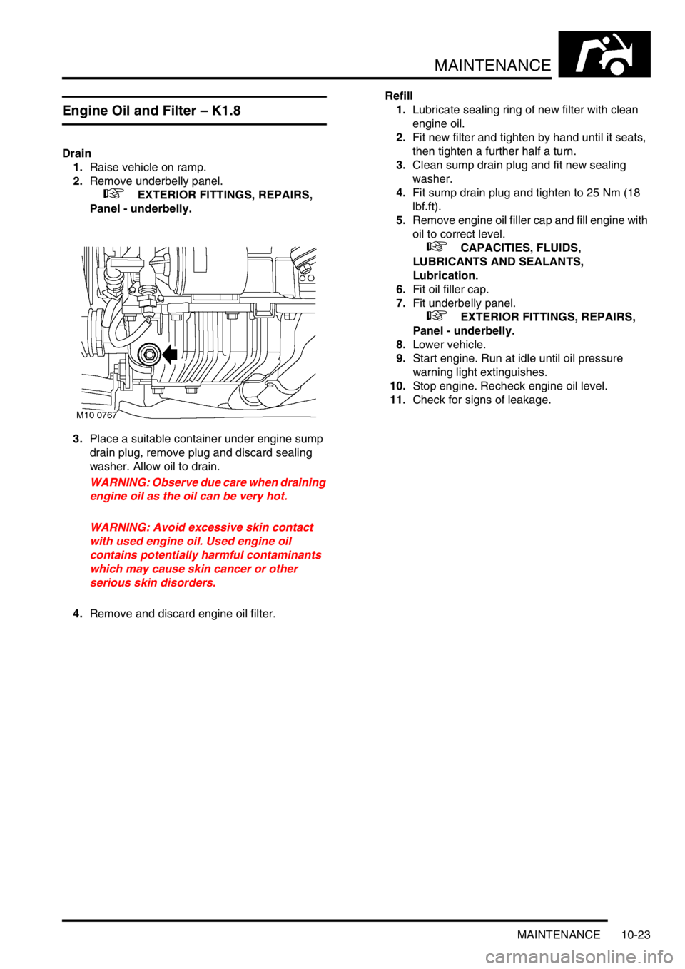
Engine Oil and Filter – K1.8
Drain
1.Raise vehicle on ramp.
2.Remove underbelly panel.
+ EXTERIOR FITTINGS, REPAIRS,
Panel - underbelly.
3.Place a suitable container under engine sump
drain plug, remove plug and discard sealing
washer. Allow oil to drain.
WARNING: Observe due care when draining
engine oil as the oil can be very hot.
WARNING: Avoid excessive skin contact
with used engine oil. Used engine oil
contains potentially harmful contaminants
which may cause skin cancer or other
serious skin disorders.
4.Remove and discard engine oil filter.Refill
1.Lubricate sealing ring of new filter with clean
engine oil.
2.Fit new filter and tighten by hand until it seats,
then tighten a further half a turn.
3.Clean sump drain plug and fit new sealing
washer.
4.Fit sump drain plug and tighten to 25 Nm (18
lbf.ft).
5.Remove engine oil filler cap and fill engine with
oil to correct level.
+ CAPACITIES, FLUIDS,
LUBRICANTS AND SEALANTS,
Lubrication.
6.Fit oil filler cap.
7.Fit underbelly panel.
+ EXTERIOR FITTINGS, REPAIRS,
Panel - underbelly.
8.Lower vehicle.
9.Start engine. Run at idle until oil pressure
warning light extinguishes.
10.Stop engine. Recheck engine oil level.
11.Check for signs of leakage.
Page 171 of 1007
MAINTENANCE
10-24 MAINTENANCE
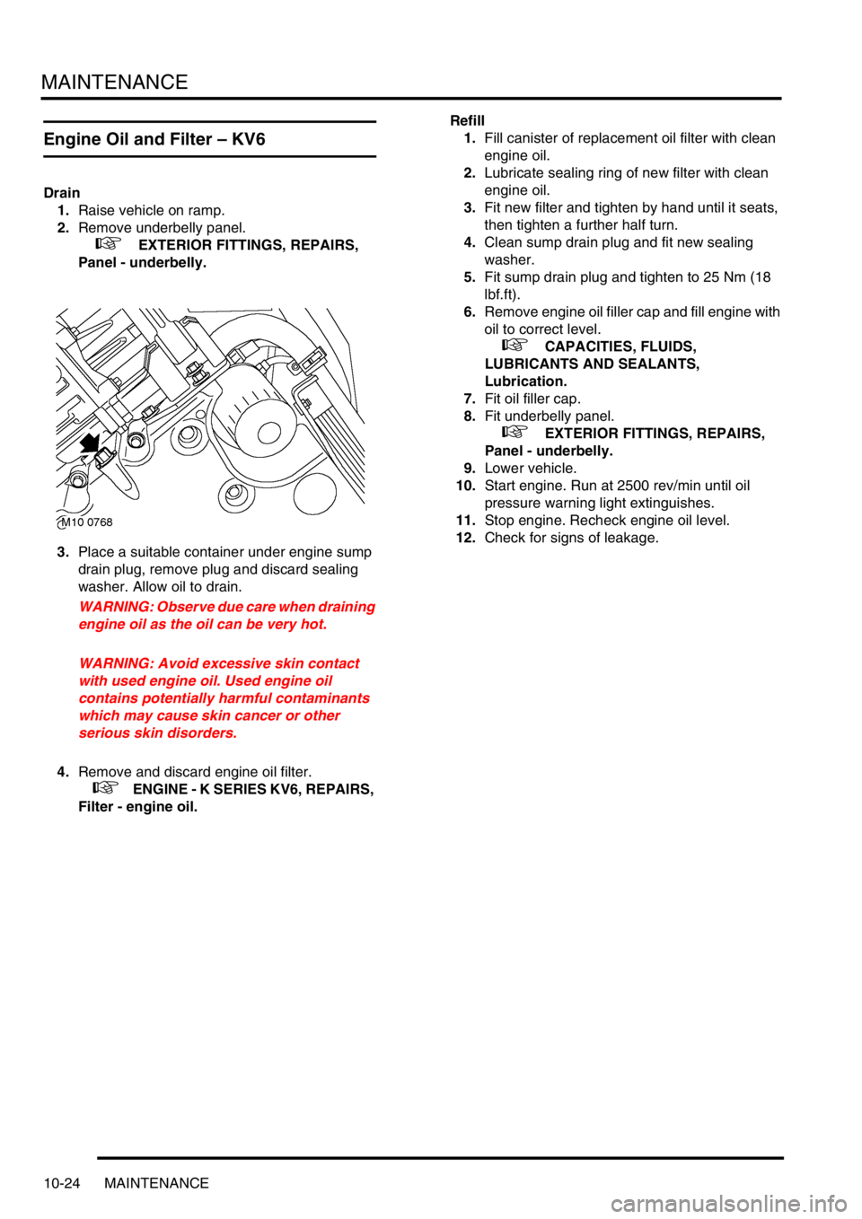
Engine Oil and Filter – KV6
Drain
1.Raise vehicle on ramp.
2.Remove underbelly panel.
+ EXTERIOR FITTINGS, REPAIRS,
Panel - underbelly.
3.Place a suitable container under engine sump
drain plug, remove plug and discard sealing
washer. Allow oil to drain.
WARNING: Observe due care when draining
engine oil as the oil can be very hot.
WARNING: Avoid excessive skin contact
with used engine oil. Used engine oil
contains potentially harmful contaminants
which may cause skin cancer or other
serious skin disorders.
4.Remove and discard engine oil filter.
+ ENGINE - K SERIES KV6, REPAIRS,
Filter - engine oil.Refill
1.Fill canister of replacement oil filter with clean
engine oil.
2.Lubricate sealing ring of new filter with clean
engine oil.
3.Fit new filter and tighten by hand until it seats,
then tighten a further half turn.
4.Clean sump drain plug and fit new sealing
washer.
5.Fit sump drain plug and tighten to 25 Nm (18
lbf.ft).
6.Remove engine oil filler cap and fill engine with
oil to correct level.
+ CAPACITIES, FLUIDS,
LUBRICANTS AND SEALANTS,
Lubrication.
7.Fit oil filler cap.
8.Fit underbelly panel.
+ EXTERIOR FITTINGS, REPAIRS,
Panel - underbelly.
9.Lower vehicle.
10.Start engine. Run at 2500 rev/min until oil
pressure warning light extinguishes.
11.Stop engine. Recheck engine oil level.
12.Check for signs of leakage.
Page 210 of 1007
ENGINE - K SERIES KV6
REPAIRS 12-3-33
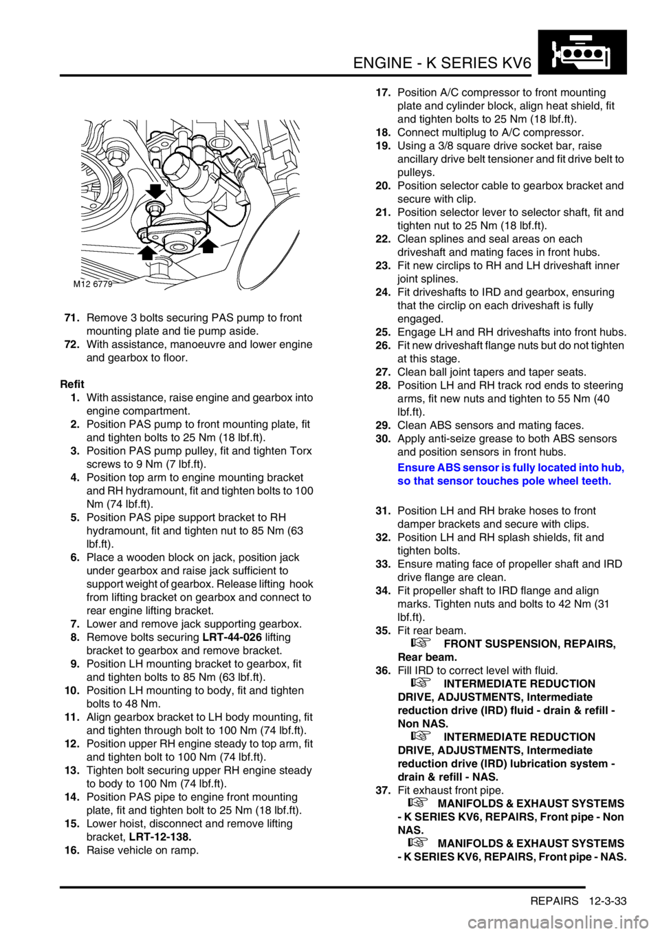
71.Remove 3 bolts securing PAS pump to front
mounting plate and tie pump aside.
72.With assistance, manoeuvre and lower engine
and gearbox to floor.
Refit
1.With assistance, raise engine and gearbox into
engine compartment.
2.Position PAS pump to front mounting plate, fit
and tighten bolts to 25 Nm (18 lbf.ft).
3.Position PAS pump pulley, fit and tighten Torx
screws to 9 Nm (7 lbf.ft).
4.Position top arm to engine mounting bracket
and RH hydramount, fit and tighten bolts to 100
Nm (74 lbf.ft).
5.Position PAS pipe support bracket to RH
hydramount, fit and tighten nut to 85 Nm (63
lbf.ft).
6.Place a wooden block on jack, position jack
under gearbox and raise jack sufficient to
support weight of gearbox. Release lifting hook
from lifting bracket on gearbox and connect to
rear engine lifting bracket.
7.Lower and remove jack supporting gearbox.
8.Remove bolts securing LRT-44-026 lifting
bracket to gearbox and remove bracket.
9.Position LH mounting bracket to gearbox, fit
and tighten bolts to 85 Nm (63 lbf.ft).
10.Position LH mounting to body, fit and tighten
bolts to 48 Nm.
11.Align gearbox bracket to LH body mounting, fit
and tighten through bolt to 100 Nm (74 lbf.ft).
12.Position upper RH engine steady to top arm, fit
and tighten bolt to 100 Nm (74 lbf.ft).
13.Tighten bolt securing upper RH engine steady
to body to 100 Nm (74 lbf.ft).
14.Position PAS pipe to engine front mounting
plate, fit and tighten bolt to 25 Nm (18 lbf.ft).
15.Lower hoist, disconnect and remove lifting
bracket, LRT-12-138.
16.Raise vehicle on ramp.17.Position A/C compressor to front mounting
plate and cylinder block, align heat shield, fit
and tighten bolts to 25 Nm (18 lbf.ft).
18.Connect multiplug to A/C compressor.
19.Using a 3/8 square drive socket bar, raise
ancillary drive belt tensioner and fit drive belt to
pulleys.
20.Position selector cable to gearbox bracket and
secure with clip.
21.Position selector lever to selector shaft, fit and
tighten nut to 25 Nm (18 lbf.ft).
22.Clean splines and seal areas on each
driveshaft and mating faces in front hubs.
23.Fit new circlips to RH and LH driveshaft inner
joint splines.
24.Fit driveshafts to IRD and gearbox, ensuring
that the circlip on each driveshaft is fully
engaged.
25.Engage LH and RH driveshafts into front hubs.
26.Fit new driveshaft flange nuts but do not tighten
at this stage.
27.Clean ball joint tapers and taper seats.
28.Position LH and RH track rod ends to steering
arms, fit new nuts and tighten to 55 Nm (40
lbf.ft).
29.Clean ABS sensors and mating faces.
30.Apply anti-seize grease to both ABS sensors
and position sensors in front hubs.
Ensure ABS sensor is fully located into hub,
so that sensor touches pole wheel teeth.
31.Position LH and RH brake hoses to front
damper brackets and secure with clips.
32.Position LH and RH splash shields, fit and
tighten bolts.
33.Ensure mating face of propeller shaft and IRD
drive flange are clean.
34.Fit propeller shaft to IRD flange and align
marks. Tighten nuts and bolts to 42 Nm (31
lbf.ft).
35.Fit rear beam.
+ FRONT SUSPENSION, REPAIRS,
Rear beam.
36.Fill IRD to correct level with fluid.
+ INTERMEDIATE REDUCTION
DRIVE, ADJUSTMENTS, Intermediate
reduction drive (IRD) fluid - drain & refill -
Non NAS.
+ INTERMEDIATE REDUCTION
DRIVE, ADJUSTMENTS, Intermediate
reduction drive (IRD) lubrication system -
drain & refill - NAS.
37.Fit exhaust front pipe.
+ MANIFOLDS & EXHAUST SYSTEMS
- K SERIES KV6, REPAIRS, Front pipe - Non
NAS.
+ MANIFOLDS & EXHAUST SYSTEMS
- K SERIES KV6, REPAIRS, Front pipe - NAS.
Page 220 of 1007
ENGINE - K SERIES KV6
REPAIRS 12-3-43
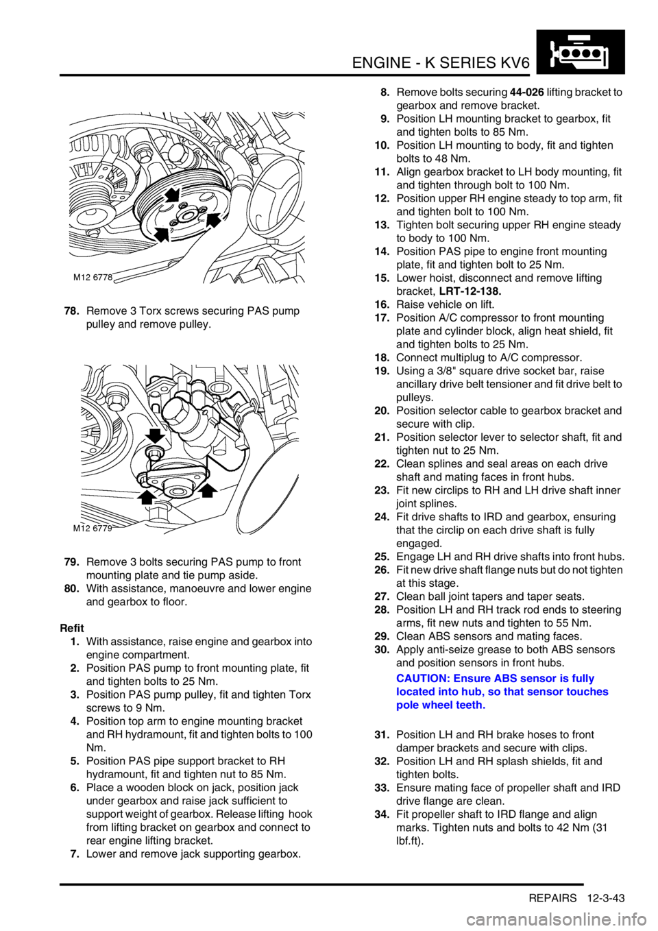
78.Remove 3 Torx screws securing PAS pump
pulley and remove pulley.
79.Remove 3 bolts securing PAS pump to front
mounting plate and tie pump aside.
80.With assistance, manoeuvre and lower engine
and gearbox to floor.
Refit
1.With assistance, raise engine and gearbox into
engine compartment.
2.Position PAS pump to front mounting plate, fit
and tighten bolts to 25 Nm.
3.Position PAS pump pulley, fit and tighten Torx
screws to 9 Nm.
4.Position top arm to engine mounting bracket
and RH hydramount, fit and tighten bolts to 100
Nm.
5.Position PAS pipe support bracket to RH
hydramount, fit and tighten nut to 85 Nm.
6.Place a wooden block on jack, position jack
under gearbox and raise jack sufficient to
support weight of gearbox. Release lifting hook
from lifting bracket on gearbox and connect to
rear engine lifting bracket.
7.Lower and remove jack supporting gearbox.8.Remove bolts securing 44-026 lifting bracket to
gearbox and remove bracket.
9.Position LH mounting bracket to gearbox, fit
and tighten bolts to 85 Nm.
10.Position LH mounting to body, fit and tighten
bolts to 48 Nm.
11.Align gearbox bracket to LH body mounting, fit
and tighten through bolt to 100 Nm.
12.Position upper RH engine steady to top arm, fit
and tighten bolt to 100 Nm.
13.Tighten bolt securing upper RH engine steady
to body to 100 Nm.
14.Position PAS pipe to engine front mounting
plate, fit and tighten bolt to 25 Nm.
15.Lower hoist, disconnect and remove lifting
bracket, LRT-12-138.
16.Raise vehicle on lift.
17.Position A/C compressor to front mounting
plate and cylinder block, align heat shield, fit
and tighten bolts to 25 Nm.
18.Connect multiplug to A/C compressor.
19.Using a 3/8" square drive socket bar, raise
ancillary drive belt tensioner and fit drive belt to
pulleys.
20.Position selector cable to gearbox bracket and
secure with clip.
21.Position selector lever to selector shaft, fit and
tighten nut to 25 Nm.
22.Clean splines and seal areas on each drive
shaft and mating faces in front hubs.
23.Fit new circlips to RH and LH drive shaft inner
joint splines.
24.Fit drive shafts to IRD and gearbox, ensuring
that the circlip on each drive shaft is fully
engaged.
25.Engage LH and RH drive shafts into front hubs.
26.Fit new drive shaft flange nuts but do not tighten
at this stage.
27.Clean ball joint tapers and taper seats.
28.Position LH and RH track rod ends to steering
arms, fit new nuts and tighten to 55 Nm.
29.Clean ABS sensors and mating faces.
30.Apply anti-seize grease to both ABS sensors
and position sensors in front hubs.
CAUTION: Ensure ABS sensor is fully
located into hub, so that sensor touches
pole wheel teeth.
31.Position LH and RH brake hoses to front
damper brackets and secure with clips.
32.Position LH and RH splash shields, fit and
tighten bolts.
33.Ensure mating face of propeller shaft and IRD
drive flange are clean.
34.Fit propeller shaft to IRD flange and align
marks. Tighten nuts and bolts to 42 Nm (31
lbf.ft).