light LAND ROVER FREELANDER 2001 Workshop Manual
[x] Cancel search | Manufacturer: LAND ROVER, Model Year: 2001, Model line: FREELANDER, Model: LAND ROVER FREELANDER 2001Pages: 1007, PDF Size: 23.47 MB
Page 14 of 1007

CONTENTS
CONTENTS 11
REAR SUSPENSION ................................................................................ 64-1
REPAIRS
Bush - trailing link............................................................................................................................ 64-1
Bearing - hub ................................................................................................................................. 64-2
Damper .......................................................................................................................................... 64-5
Trailing arm .................................................................................................................................... 64-8
Bush - trailing arm .......................................................................................................................... 64-9
Link - adjustable - transverse ......................................................................................................... 64-10
Link - transverse fixed .................................................................................................................... 64-11
Bush - link - transverse .................................................................................................................. 64-12
Sub frame ...................................................................................................................................... 64-13
BRAKES ................................................................................................... 70-1
ADJUSTMENTS
Brake bleed ..................................................................................................................................... 70-1
Cable - handbrake - check and adjust ............................................................................................ 70-2
REPAIRS
Drum - rear ...................................................................................................................................... 70-3
Disc - front....................................................................................................................................... 70-5
Hose - front - primary - LH .............................................................................................................. 70-6
Hose - rear ...................................................................................................................................... 70-7
Cylinder - master - tandem - LHD ................................................................................................... 70-8
Cylinder - master - tandem - RHD................................................................................................... 70-9
Lever assembly - handbrake........................................................................................................... 70-10
Cable - handbrake ......................................................................................................................... 70-11
Switch - handbrake warning ............................................................................................................ 70-12
Switch - stop light ............................................................................................................................ 70-13
Sensor - brake pedal position ........................................................................................................ 70-13
Shoes/pads - front - set................................................................................................................... 70-14
Brake Shoes - rear set .................................................................................................................... 70-15
Servo assembly - LHD .................................................................................................................... 70-17
Servo assembly - RHD ................................................................................................................... 70-19
Vacuum pump - Td4 - manual ........................................................................................................ 70-20
Vacuum pump - Td4 - automatic ..................................................................................................... 70-21
Vacuum - enhancer - KV6 .............................................................................................................. 70-22
Carrier assembly - calliper - front ................................................................................................... 70-23
Wheel cylinder - rear ....................................................................................................................... 70-24
Switch - low fluid level ..................................................................................................................... 70-25
Sensor & harness - front wheel - RH .............................................................................................. 70-25
Sensor & harness - front wheel - LH ............................................................................................... 70-27
Sensor & harness - rear wheel ....................................................................................................... 70-29
Modulator unit ................................................................................................................................. 70-30
Switch - hill descent - from 04MY ................................................................................................... 70-31
Switch - hill descent - up to 03MY................................................................................................... 70-32
Page 15 of 1007

CONTENTS
12 CONTENTS
RESTRAINT SYSTEMS ............................................................................ 75-1
REPAIRS
Automatic belt assembly - front - 3 door ......................................................................................... 75-1
Automatic belt assembly - front - 5 door ......................................................................................... 75-2
Seat belt - centre - rear ................................................................................................................... 75-3
Seat belt - rear - LH ........................................................................................................................ 75-4
Adjustable mounting - seat belt - 'B' pillar ....................................................................................... 75-5
Stalk - rear seat belt - LH - 3 door .................................................................................................. 75-6
Stalk - rear seat belt - LH - 5 door .................................................................................................. 75-7
Pre-tensioner - seat belt - front ....................................................................................................... 75-8
Pre-tensioner - seat belt - front - deployment - off vehicle ............................................................. 75-9
Stalk - rear seat belt - centre .......................................................................................................... 75-11
Air bag - steering wheel .................................................................................................................. 75-13
Air bag - fascia - passenger - up to 04MY ...................................................................................... 75-14
Air bag - fascia - passenger - from 04MY ....................................................................................... 75-15
Diagnostic control unit (DCU) ........................................................................................................ 75-16
Airbag - passenger - deployment - off vehicle ............................................................................... 75-17
Rotary coupler - (SRS) air bag system ........................................................................................... 75-19
Airbag module - steering wheel - deployment - off vehicle ............................................................ 75-20
Airbag module - steering wheel - deployment - in-vehicle .............................................................. 75-21
Pre-tensioner - front seatbelt - deployment - in-vehicle .................................................................. 75-23
DOORS...................................................................................................... 76-1-1
ADJUSTMENTS
Door - front or rear - adjust on striker ............................................................................................ 76-1-1
Door - front - align on hinges .......................................................................................................... 76-1-2
REPAIRS
Door assembly - front - remove for access & refit .......................................................................... 76-1-3
Door assembly - rear - remove for access & refit ........................................................................... 76-1-4
Door - tail assembly - remove for access & refit ............................................................................. 76-1-5
Glass - front door .......................................................................................................................... 76-1-6
Glass - rear door ............................................................................................................................ 76-1-7
Rubber/felt - glass channel - front door ........................................................................................ 76-1-8
Rubber/felt - glass channel - rear door .......................................................................................... 76-1-9
Glass - tail door .............................................................................................................................. 76-1-10
Quarter light - rear door .................................................................................................................. 76-1-11
Glass regulator - tail door .............................................................................................................. 76-1-12
Seal - waist inner - tail door ............................................................................................................ 76-1-13
Trim casing - front door - 3 door .................................................................................................... 76-1-14
Trim casing - front door - 5 door - up to 04MY................................................................................ 76-1-15
Trim casing - front door - 5 door - from 04MY ................................................................................ 76-1-16
Trim casing - rear door - up to 04MY .............................................................................................. 76-1-18
Trim casing - rear door - from 04MY............................................................................................... 76-1-20
Trim casing - tail door ..................................................................................................................... 76-1-22
Plastic sheet - front door - lower - 3 door........................................................................................ 76-1-23
Pocket - front door - 3 door ............................................................................................................. 76-1-23
Plastic sheet - front door - upper - 3 door ....................................................................................... 76-1-24
Plastic sheet - tail door ................................................................................................................... 76-1-24
Plastic sheet - front door - 5 door .................................................................................................. 76-1-25
Plastic sheet - rear door.................................................................................................................. 76-1-25
Latch - front door - 3 door ............................................................................................................... 76-1-26
Latch - front door - 5 door .............................................................................................................. 76-1-27
Latch - rear door ............................................................................................................................. 76-1-28
Latch - tail door ............................................................................................................................... 76-1-29
Page 23 of 1007

CONTENTS
20 CONTENTS
LIGHTING.................................................................................................. 86-2-1
ADJUSTMENTS
Headlamps - pair - align beam - up to 04MY .................................................................................. 86-2-1
Headlamps - pair - align beam - from 04MY ................................................................................... 86-2-1
REPAIRS
Headlamp assembly - up to 04MY.................................................................................................. 86-2-3
Headlamp assembly - from 04MY .................................................................................................. 86-2-4
Lamp assembly - flasher side repeater - front ................................................................................ 86-2-5
Lamp assembly - tail ....................................................................................................................... 86-2-5
Lamp assembly - number plate ...................................................................................................... 86-2-6
Lamp assembly - fog/driving - from 04MY ...................................................................................... 86-2-6
Lamp assembly - rear ..................................................................................................................... 86-2-7
Lamp assembly - centre high mounted stop (CHMSL) ................................................................... 86-2-7
Lamp assembly - glove compartment ............................................................................................. 86-2-8
Lamp assembly - load space .......................................................................................................... 86-2-8
Switch - headlamp levelling ............................................................................................................ 86-2-9
Switch - glove compartment ........................................................................................................... 86-2-9
Switch - hazard warning ................................................................................................................. 86-2-10
Switch - combined direction indicator/headlight/horn ..................................................................... 86-2-10
Switch - rear fog lamp ..................................................................................................................... 86-2-11
CONTROL UNITS ..................................................................................... 86-3-1
REPAIRS
Control unit - window lift ................................................................................................................. 86-3-1
Relay - power folding mirrors - from 02MY ..................................................................................... 86-3-1
Central Control Unit (CCU) ............................................................................................................. 86-3-2
Control Unit - power fold mirrors - up to 02MY ............................................................................... 86-3-3
SECURITY................................................................................................. 86-4-1
REPAIRS
Solenoid/motor - taildoor................................................................................................................. 86-4-1
Switch/push - horn .......................................................................................................................... 86-4-2
Horn ................................................................................................................................................ 86-4-2
Immobilisation - electronic control unit (ECU) - ............................................................................. 86-4-3
Sensor - volumetric - alarm system - 3 door ................................................................................... 86-4-3
Module (ECU) - volumetric - alarm system - 5 door - without sunroof ........................................... 86-4-5
Module (ECU) - volumetric - alarm system - 5 door - with sunroof ................................................ 86-4-7
Receiver - alarm system ................................................................................................................. 86-4-10
Coil - passive immobilisation - alarm system .................................................................................. 86-4-10
Page 24 of 1007

CONTENTS
CONTENTS 21
WINDOWS ................................................................................................ 86-5-1
REPAIRS
Motor & control unit - front door - 3 door ......................................................................................... 86-5-1
Motor & control unit - front door - 5 door ......................................................................................... 86-5-2
Switch - master window - 5 door - from 04MY ................................................................................ 86-5-2
Relay - control - tail door glass ....................................................................................................... 86-5-3
Microswitch - hardtop sensing - 3 door ........................................................................................... 86-5-4
Relay - heated front screen ........................................................................................................... 86-5-5
Switch - backlight heater ................................................................................................................. 86-5-6
IN CAR ENTERTAINMENT ...................................................................... 86-6-1
REPAIRS
Radio - up to 04MY ......................................................................................................................... 86-6-1
Radio/CD - from 04MY .................................................................................................................... 86-6-2
Speaker - rear - 3 door .................................................................................................................... 86-6-3
Speaker - rear - 5 door .................................................................................................................... 86-6-3
Speaker - front ................................................................................................................................ 86-6-4
Aerial - manual - 3 door .................................................................................................................. 86-6-4
Aerial - manual - 5 door .................................................................................................................. 86-6-5
Coaxial lead - front aerial - 3 door ................................................................................................... 86-6-6
Coaxial lead - front aerial - 5 door ................................................................................................... 86-6-7
Speaker - tweeter - front ................................................................................................................. 86-6-8
Speaker - tweeter - rear - 3 door ..................................................................................................... 86-6-9
Amplifier - power ............................................................................................................................ 86-6-10
Sub-woofer assembly .................................................................................................................... 86-6-11
Coaxial lead - extension.................................................................................................................. 86-6-12
HARNESSES ............................................................................................ 86-7-1
REPAIRS
Fuse box - passenger compartment ............................................................................................... 86-7-1
Harness - main ................................................................................................................................ 86-7-2
Harness - tailgate ............................................................................................................................ 86-7-12
Harness - interior lights - 5 door ...................................................................................................... 86-7-15
Harness - front door - 5 door ........................................................................................................... 86-7-15
Harness - rear door ......................................................................................................................... 86-7-16
DRIVER CONTROLS ................................................................................ 86-8-1
REPAIRS
Switch - remote control - audio system .......................................................................................... 86-8-1
Switch - park distance control (PDC) - from 04 MY ........................................................................ 86-8-1
Control unit (ECU) - parking aid - from 04MY ................................................................................. 86-8-2
Sensor - parking aid - rear - from 04MY ......................................................................................... 86-8-2
Sounder - parking aid - rear - from 04MY ....................................................................................... 86-8-3
Switch - handbrake warning ............................................................................................................ 86-8-3
Switch - hazard warning - from 04MY ............................................................................................. 86-8-4
Cigar lighter - front .......................................................................................................................... 86-8-4
Switch - control - exterior mirror ...................................................................................................... 86-8-5
Page 29 of 1007

INTRODUCTION
01-4
HRW Heated Rear Window
ht/HT High tension
HSLA High Strength Low Alloy
IACV Idle Air Control Valve
IAT Intake Air Temperature
ICE In-Car Entertainment
i.dia. Internal diameter
IDM Intelligent Driver Module
IF Intermediate Frequency
in Inch
in
2Square inch
in3Cubic inch
ILT Inlet Throttle
ISO International Organisation for
Standardisation
ITS Inflatable Tubular Structure
k Thousand
kg Kilogramme
kg/h Kilogrammes per hour
km Kilometre
km/h Kilometres per hour
kPa KiloPascal
KS Knock Sensor
lb(s) Pounds
lbf Pounds force
lbf.in Pounds force inches
lbf/in
2Pounds per square inch
lbf.ft Pounds force feet
λLambda
lc Low compression
LCD Liquid Crystal Display
LED Light Emitting Diode
LEV Low Emission Vehicle
LH Left-Hand
LHD Left-Hand Drive
LSM Light Switch Module
LVS Liquid Vapour Separator
mMetre
µMicro
MAF Mass Air Flow
MAP Manifold Absolute Pressure
MFU Multi-Function Unit
MFL Multi-Function Logic
max. Maximum
MEMS Modular Engine Management
System
MIG Metal/Inert Gas
MIL Malfunction Indicator Lamp
MPa MegaPascal
MOSFET Metal Oxide Semiconductor Field
Effect Transistor
min. Minimum
- Minus (tolerance)
' Minute (angle)
mm Millimetre
mph Miles per hour MPi Multi-Point injection
MV Motorised Valve
MY Model Year
NAS North American Specification
(-) Negative (electrical)
Nm Newton metre
No. Number
NO
2Nitrogen Dioxide
NO
xOxides of Nitrogen
NTC Negative Temperature
Coefficient
NRV Non Return Valve
OBD On Board Diagnostics
OBM On Board Monitoring
o.dia. Outside diameter
OAT Organic Acid Technology
ORM Off-road Mode
ΩOhm
PAS Power Assisted Steering
PCB Printed Circuit Board
PCV Positive Crankcase Ventilation
PDC Parking Distance Control
PDOP Position Dilation Of Precision
PI Programme Information
PPS Pulse Per Second
PS Programme Service
psi Pounds per square inch
pts. Pints
% Percentage
+ Plus (tolerance) or Positive
(electrical)
±Plus or minus (tolerance)
PTC Positive Temperature Coefficient
PTFE Polytetrafluorethylene
PWM Pulse Width Modulation
RDS Radio Data Service
rRadius
:Ratio
ref Reference
REG Regionalisation
RES Rover Engineering Standards
rev/min Revolutions per minute
RF Radio Frequency
RGB Red / Green / Blue
RH Right-Hand
RHD Right-Hand Drive
ROM Read Only Memory
RON Research Octane Number
ROV Roll Over Valve
ROW Rest Of World
SAE Society of Automotive Engineers
SAI Secondary Air Injection
" Second (angle)
SLABS Self Levelling and Anti-Lock
Brake System
SLS Self Levelling Suspension
SOHC Single Overhead Camshaft
SPE Single Point Entry
Page 36 of 1007

GENERAL INFORMATION
03-5
Local issues
A number of environmental issues will be of
particular concern to residents and other neighbours
close to the site. The sensitivity of these issues will
depend on the proximity of the site and the layout
and amount of activity carried on at the site.
Noise is a major concern and therefore consideration
should be given to the time spent carrying out noisy
activities and the location of those activities that can
cause excessive noise.
Car alarm testing, panel beating, hammering and
other such noisy activities should, whenever
possible, be carried out indoors with doors and
windows shut, or as far away from houses as
possible.
Running vehicle engines may be an outside activity
which could cause nuisance to neighbours because
of both noise and smell.
Be sensitive to the time of day when these activities
are carried out and minimise the time of the noisy
operation, particularly in the early morning and late
evening.
Another local concern will be the smell from the
various materials used. Using less solvent, paint and
petrol could help prevent this annoyance.
Local residents and other business users will also be
concerned about traffic congestion, noise and
exhaust fumes, be sensitive to these concerns and
try to minimise inconvenience from deliveries,
customers and servicing operations.
Checklist
Always adhere to the following:
lidentify where the neighbours who are likely to
be affected are situated;
lminimise noise, smells and traffic nuisance;
lprevent litter by putting waste in the correct
containers;
lhave waste skips emptied regularly.Use of resource
Another environmental concern is the waste of
materials and energy that can occur in day to day
activities.
Electricity for heating, lighting and compressed air
uses resources and releases pollution during its
generation.
Fuel used for heating, running cars or vans and
mobile plant is another limited resource which
consumes large amounts of energy during its
extraction and refining processes.
Water has to be cleaned, piped to site and disposed
of, all of which creates more potential pollution;
Oil, spares, paint etc., have all produced pollution in
the process of manufacture and they become a
waste disposal problem if discarded.
Checklist
Always adhere to the following:
Electricity and heating –
lkeep doors and windows closed in the winter;
lswitch off machinery or lights when not needed;
luse energy efficient heating systems;
lswitch off computers and photocopiers when
not needed.
Fuel –
ldon't run engines unnecessarily;
lthink about whether journeys are necessary and
drive to conserve fuel.
Water –
ldon't leave taps and hose pipes running;
lmend leaks quickly, don't be wasteful.
Compressed air –
ldon't leave valves open;
lmend leaks quickly;
ldon't leave the compressor running when not
needed.
Use of environmentally damaging materials –
lcheck whether a less toxic material is available.
Handling and storage of materials –
lhave the correct facilities available for handling
liquids to prevent spillage and wastage as listed
above;
lprovide suitable locations for storage to prevent
frost damage or other deterioration.
Page 38 of 1007

GENERAL INFORMATION
03-7
General fitting instructions
Precautions against damage
To avoid damage to the vehicle when carrying out
repairs, always adhere to the following:
lAlways fit wing and seat covers before
commencing work. Avoid spilling brake fluid or
battery acid on paintwork; immediately wash off
with water if this occurs.
lDisconnect the battery earth lead before starting
work, see ELECTRICAL PRECAUTIONS.
lAlways use the recommended service tool or a
satisfactory equivalent where specified.
lProtect exposed bearing surfaces, sealing
surfaces and screw threads from damage.
Component removal
Whenever possible, clean components and
surrounding area before removal.
lBlank off openings exposed by component
removal.
lImmediately seal fuel, oil or hydraulic lines when
apertures are exposed; use plastic caps or
plugs to prevent loss of fluid and ingress of dirt.
lClose open ends of oilways exposed by
component removal with tapered hardwood
plugs or conspicuous plastic plugs.
lImmediately a component is removed, place it in
a suitable container; use a separate container
for each component and its associated parts.
lClean bench and provide marking materials,
labels, containers and locking wire before
dismantling a component.
Dismantling
Observe scrupulous cleanliness when dismantling
components, particularly when brake, fuel or
hydraulic system parts are being worked on. A
particle of dirt or a cloth fragment could cause a
serious malfunction if trapped in these systems.Use the following procedures:
lBlow out all tapped holes, crevices, oilways and
fluid passages with an air line. Ensure that any
O-rings used for sealing are correctly replaced
or renewed if disturbed during the process.
lUse marking ink to identify mating parts and
ensure correct reassembly. Do not use a centre
punch or scriber to mark parts, they could
initiate cracks or distortion in marked
components.
lWire together mating parts where necessary to
prevent accidental interchange (e.g. roller
bearing components).
lWire labels on to all parts which are to be
renewed, and to parts requiring further
inspection before being passed for reassembly;
place these parts in separate containers from
those containing parts for rebuild.
lDo not discard a part due for renewal until after
comparing it with a new part to ensure that its
correct replacement has been obtained.
Cleaning components
Always use the recommended cleaning agent or
equivalent. Ensure that adequate ventilation is
provided when volatile degreasing agents are being
used. Do not use degreasing equipment for
components containing items which could be
damaged by the use of this process.
When washing under bonnet, never direct water onto
ECM, as water ingress may occur resulting in
damage to electrical components inside.
General Inspection
All components should be inspected for wear or
damage before being reassembled.
lNever inspect a component for wear or
dimensional check unless it is absolutely clean;
a slight smear of grease can conceal an
incipient failure.
lWhen a component is to be checked
dimensionally against recommended values,
use the appropriate measuring equipment
(surface plates, micrometers, dial gauges etc.).
Ensure the measuring equipment is calibrated
and in good serviceable condition.
lReject a component if its dimensions are
outside the specified tolerances, or if it appears
to be damaged.
lA part may be refitted if its critical dimension is
exactly to its tolerance limit and it appears to be
in satisfactory condition.
lUse 'Plastigauge' 12 Type PG-1 for checking
bearing surface clearances.
Page 42 of 1007

GENERAL INFORMATION
03-11
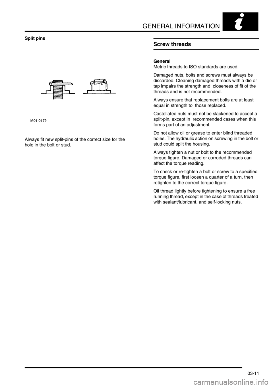
Split pins
Always fit new split-pins of the correct size for the
hole in the bolt or stud.
Screw threads
General
Metric threads to ISO standards are used.
Damaged nuts, bolts and screws must always be
discarded. Cleaning damaged threads with a die or
tap impairs the strength and closeness of fit of the
threads and is not recommended.
Always ensure that replacement bolts are at least
equal in strength to those replaced.
Castellated nuts must not be slackened to accept a
split-pin, except in recommended cases when this
forms part of an adjustment.
Do not allow oil or grease to enter blind threaded
holes. The hydraulic action on screwing in the bolt or
stud could split the housing.
Always tighten a nut or bolt to the recommended
torque figure. Damaged or corroded threads can
affect the torque reading.
To check or re-tighten a bolt or screw to a specified
torque figure, first loosen a quarter of a turn, then
retighten to the correct torque figure.
Oil thread lightly before tightening to ensure a free
running thread, except in the case of threads treated
with sealant/lubricant, and self-locking nuts.
Page 44 of 1007

GENERAL INFORMATION
03-13
Self-locking bolts and screws
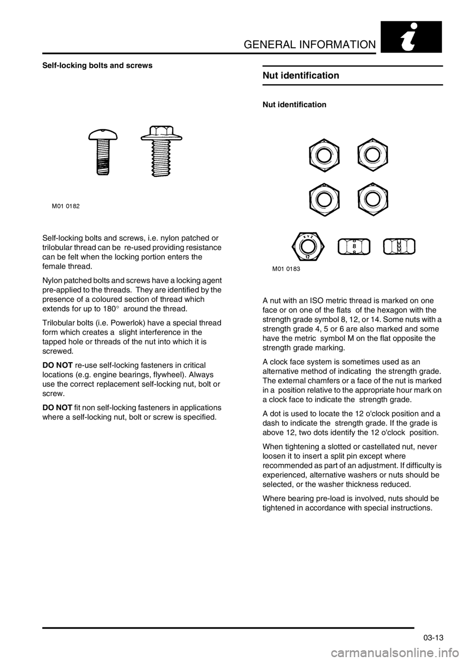
Self-locking bolts and screws, i.e. nylon patched or
trilobular thread can be re-used providing resistance
can be felt when the locking portion enters the
female thread.
Nylon patched bolts and screws have a locking agent
pre-applied to the threads. They are identified by the
presence of a coloured section of thread which
extends for up to 180° around the thread.
Trilobular bolts (i.e. Powerlok) have a special thread
form which creates a slight interference in the
tapped hole or threads of the nut into which it is
screwed.
DO NOT re-use self-locking fasteners in critical
locations (e.g. engine bearings, flywheel). Always
use the correct replacement self-locking nut, bolt or
screw.
DO NOT fit non self-locking fasteners in applications
where a self-locking nut, bolt or screw is specified.
Nut identification
Nut identification
A nut with an ISO metric thread is marked on one
face or on one of the flats of the hexagon with the
strength grade symbol 8, 12, or 14. Some nuts with a
strength grade 4, 5 or 6 are also marked and some
have the metric symbol M on the flat opposite the
strength grade marking.
A clock face system is sometimes used as an
alternative method of indicating the strength grade.
The external chamfers or a face of the nut is marked
in a position relative to the appropriate hour mark on
a clock face to indicate the strength grade.
A dot is used to locate the 12 o'clock position and a
dash to indicate the strength grade. If the grade is
above 12, two dots identify the 12 o'clock position.
When tightening a slotted or castellated nut, never
loosen it to insert a split pin except where
recommended as part of an adjustment. If difficulty is
experienced, alternative washers or nuts should be
selected, or the washer thickness reduced.
Where bearing pre-load is involved, nuts should be
tightened in accordance with special instructions.
Page 47 of 1007

GENERAL INFORMATION
03-16
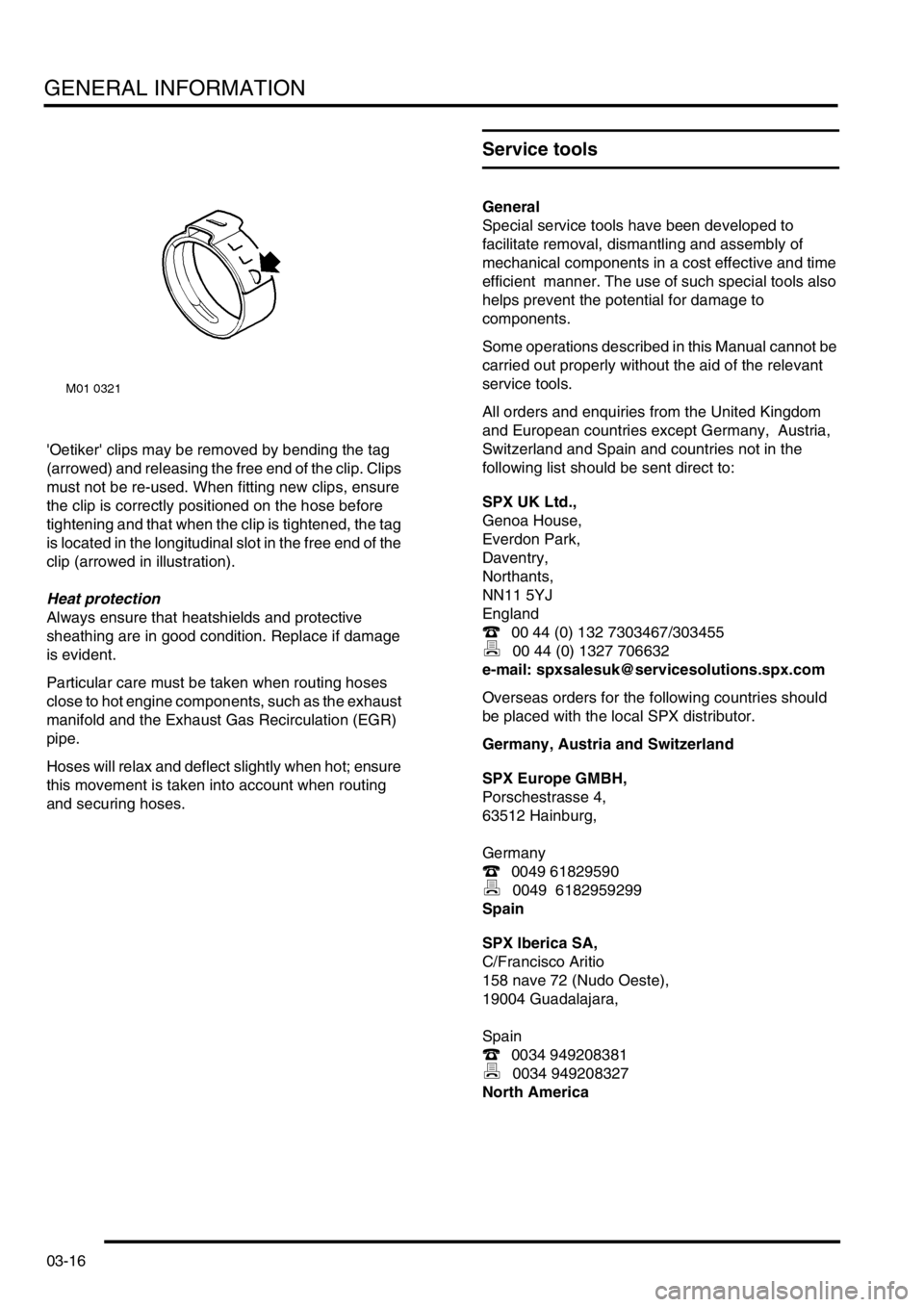
'Oetiker' clips may be removed by bending the tag
(arrowed) and releasing the free end of the clip. Clips
must not be re-used. When fitting new clips, ensure
the clip is correctly positioned on the hose before
tightening and that when the clip is tightened, the tag
is located in the longitudinal slot in the free end of the
clip (arrowed in illustration).
Heat protection
Always ensure that heatshields and protective
sheathing are in good condition. Replace if damage
is evident.
Particular care must be taken when routing hoses
close to hot engine components, such as the exhaust
manifold and the Exhaust Gas Recirculation (EGR)
pipe.
Hoses will relax and deflect slightly when hot; ensure
this movement is taken into account when routing
and securing hoses.
Service tools
General
Special service tools have been developed to
facilitate removal, dismantling and assembly of
mechanical components in a cost effective and time
efficient manner. The use of such special tools also
helps prevent the potential for damage to
components.
Some operations described in this Manual cannot be
carried out properly without the aid of the relevant
service tools.
All orders and enquiries from the United Kingdom
and European countries except Germany, Austria,
Switzerland and Spain and countries not in the
following list should be sent direct to:
SPX UK Ltd.,
Genoa House,
Everdon Park,
Daventry,
Northants,
NN11 5YJ
England
( 00 44 (0) 132 7303467/303455
) 00 44 (0) 1327 706632
e-mail: [email protected]
Overseas orders for the following countries should
be placed with the local SPX distributor.
Germany, Austria and Switzerland
SPX Europe GMBH,
Porschestrasse 4,
63512 Hainburg,
Germany
( 0049 61829590
) 0049 6182959299
Spain
SPX Iberica SA,
C/Francisco Aritio
158 nave 72 (Nudo Oeste),
19004 Guadalajara,
Spain
( 0034 949208381
) 0034 949208327
North America