wheel torque LAND ROVER FREELANDER 2001 User Guide
[x] Cancel search | Manufacturer: LAND ROVER, Model Year: 2001, Model line: FREELANDER, Model: LAND ROVER FREELANDER 2001Pages: 1007, PDF Size: 23.47 MB
Page 131 of 1007

TORQUE WRENCH SETTINGS
06-28
Brakes
1 Use NEW bolts
TORQUE DESCRIPTION METRIC IMPERIAL
ABS ECU pipe unions 17 Nm 12 lbf.ft
ABS modulator to mounting bracket bolts 9 Nm 7 lbf.ft
ABS modulator mounting bracket to inner wing:
⇒ Nuts
⇒ Bolts13 Nm
8 Nm10 lbf.ft
6 lbf.ft
Bleed screw - front calipers 10 Nm 7.5 lbf.ft
Brake servo to bulkhead nuts 22 Nm 16 lbf.ft
EGR cooler to mounting bolts 25 Nm 18 lbf.ft
EGR pipe support bracket to engine lifting bracket bolts 25 Nm 18 lbf.ft
Front caliper brake hose banjo bolt 28 Nm 21 lbf.ft
Front caliper guide pin bolts 27 Nm 20 lbf.ft
Front caliper mounting bolts 100 Nm 74 lbf.ft
Front disc shield to hub screw 8.5 Nm 6.3 lbf.ft
Front disc to drive flange screws 5 Nm 3.7 lbf.ft
Fuel rail to support bracket bolt 10 Nm 7.5 lbf.ft
Handbrake cable to body and subframe bolts 22 Nm 16 lbf.ft
Handbrake cable retaining plate bolts 22 Nm 16 lbf.ft
Handbrake lever assembly to body bolts 22 Nm 16 lbf.ft
Hill Descent Control (HDC) switch bolt 5 Nm 3.5 lbf.ft
Master cylinder to servo nuts 25 Nm 18 lbf.ft
PAS oil cooler pipe bolts 10 Nm 7.5 lbf.ft
Primary and secondary brake pipe union nuts 17 Nm 12 lbf.ft
Rear wheel cylinder pipe union nut 17 Nm 12 lbf.ft
Rear wheel cylinder to backplate bolts 8 Nm 6 lbf.ft
Reservoir to master cylinder (LHD) Torx bolt 8 Nm 6 lbf.ft
Reservoir to master cylinder (LHD) Torx bolt 6 Nm 4.5 lbf.ft
Road wheel nuts 115 Nm 85 lbf.ft
Turbocharger intercooler pipe to support bracket bolt 10 Nm 7.5 lbf.ft
Turbocharger pipe to coolant rail bolt 25 Nm 18 lbf.ft
Vacuum pump bolts
122 Nm 16 lbf.ft
Vacuum reservoir to mounting bracket nut 10 Nm 7.5 lbf.ft
Page 132 of 1007
TORQUE WRENCH SETTINGS
06-29
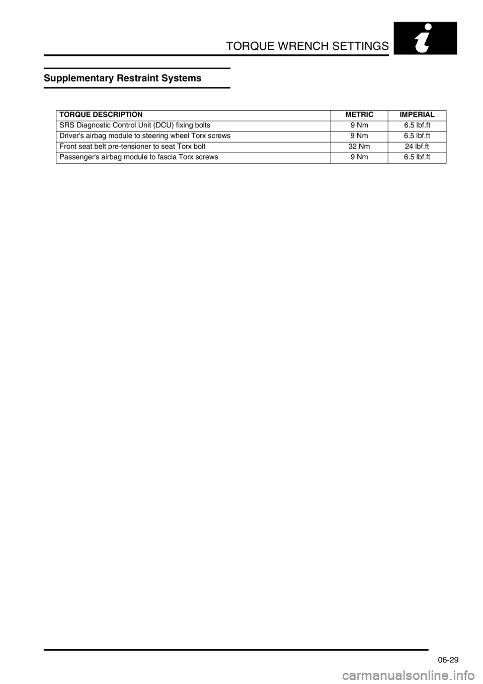
Supplementary Restraint Systems
TORQUE DESCRIPTION METRIC IMPERIAL
SRS Diagnostic Control Unit (DCU) fixing bolts 9 Nm 6.5 lbf.ft
Driver's airbag module to steering wheel Torx screws 9 Nm 6.5 lbf.ft
Front seat belt pre-tensioner to seat Torx bolt 32 Nm 24 lbf.ft
Passenger's airbag module to fascia Torx screws 9 Nm 6.5 lbf.ft
Page 133 of 1007

TORQUE WRENCH SETTINGS
06-30
Body
TORQUE DESCRIPTION METRIC IMPERIAL
Doors
Door lock striker to body screws 10 Nm 7 lbf.ft
Door stiffener Torx screws 9 Nm 7 lbf.ft
Front door control unit to glass clamp bolts 9 Nm 7 lbf.ft
Front door hinge bolts 30 Nm 22 lbf.ft
Rear door glass clamp bolts 8 Nm 6 lbf.ft
Tail door exterior handle nuts 5 Nm 3.7 lbf.ft
Tail door glass clamp bolts 8 Nm 6 lbf.ft
Tail door glass regulator lock nuts 14 Nm 10 lbf.ft
Tail door hinge bolts 30 Nm 22 lbf.ft
Exterior Fittings
Bonnet hinge, bolts 9 Nm 6.5 lbf.ft
Bonnet release lever to 'A' post bolt 9 Nm 6.5 lbf.ft
Exterior mirror to door Torx screws 6 Nm 4.4 lbf.ft
Front wing bolts5 Nm 3.7 lbf.ft
Spare wheel mounting bracket:
⇒ Bolts13 Nm 10 lbf.ft
⇒ Nuts25 Nm 18 lbf.ft
Spare wheel to bracket retention nuts 45 Nm 33 lbf.ft
Splash shield bolts 10 Nm 7 lbf.ft
Underbelly panel to body bolts 45 Nm 33 lbf.ft
Underbelly panel to body rear screws 8 Nm 6 lbf.ft
3 door vehicles
Hard back catch Torx screws 10 Nm 7.5 lbf.ft
Hard back retainer Torx screws 10 Nm 7.5 lbf.ft
Soft back support bracket bolts 25 Nm 18 lbf.ft
5 door vehicles
Roof rack side rail bolts 22 Nm 16 lbf.ft
Interior Trim Components
Engine compartment fusebox bolts 8 Nm 6 lbf.ft
Passenger compartment fusebox mounting plate to body and steering column
bracket bolts8 Nm 6 lbf.ft
Passenger compartment fusebox to mounting plate bolts 8 Nm 6 lbf.ft
Seats
Front seat runner to body bolts 45 Nm 33 lbf.ft
Front seat squab frame to cushion frame Torx bolts 45 Nm 33 lbf.ft
Rear bench seat to body bolts 25 Nm 18 lbf.ft
Rear seat cushion to squab Torx bolts 28 Nm 21 lbf.ft
Rear seat catch assembly Torx bolts 32 Nm 24 lbf.ft
Rear seat squab lock Torx screws 20 Nm 15 lbf.ft
Rear seat squab to cushion Torx bolts 28 Nm 21 lbf.ft
Rear seat hinge Torx bolts 25 Nm 18 lbf.ft
Page 153 of 1007
MAINTENANCE
10-6 MAINTENANCE
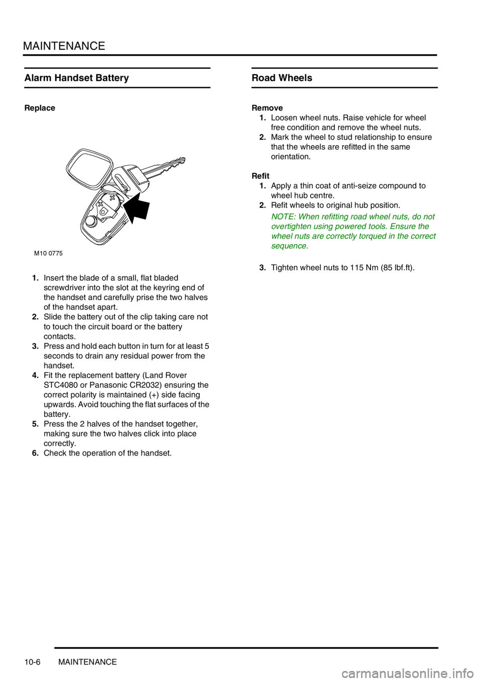
Alarm Handset Battery
Replace
1.Insert the blade of a small, flat bladed
screwdriver into the slot at the keyring end of
the handset and carefully prise the two halves
of the handset apart.
2.Slide the battery out of the clip taking care not
to touch the circuit board or the battery
contacts.
3.Press and hold each button in turn for at least 5
seconds to drain any residual power from the
handset.
4.Fit the replacement battery (Land Rover
STC4080 or Panasonic CR2032) ensuring the
correct polarity is maintained (+) side facing
upwards. Avoid touching the flat surfaces of the
battery.
5.Press the 2 halves of the handset together,
making sure the two halves click into place
correctly.
6.Check the operation of the handset.
Road Wheels
Remove
1.Loosen wheel nuts. Raise vehicle for wheel
free condition and remove the wheel nuts.
2.Mark the wheel to stud relationship to ensure
that the wheels are refitted in the same
orientation.
Refit
1.Apply a thin coat of anti-seize compound to
wheel hub centre.
2.Refit wheels to original hub position.
NOTE: When refitting road wheel nuts, do not
overtighten using powered tools. Ensure the
wheel nuts are correctly torqued in the correct
sequence.
3.Tighten wheel nuts to 115 Nm (85 lbf.ft).
Page 174 of 1007
MAINTENANCE
MAINTENANCE 10-27
Suspension
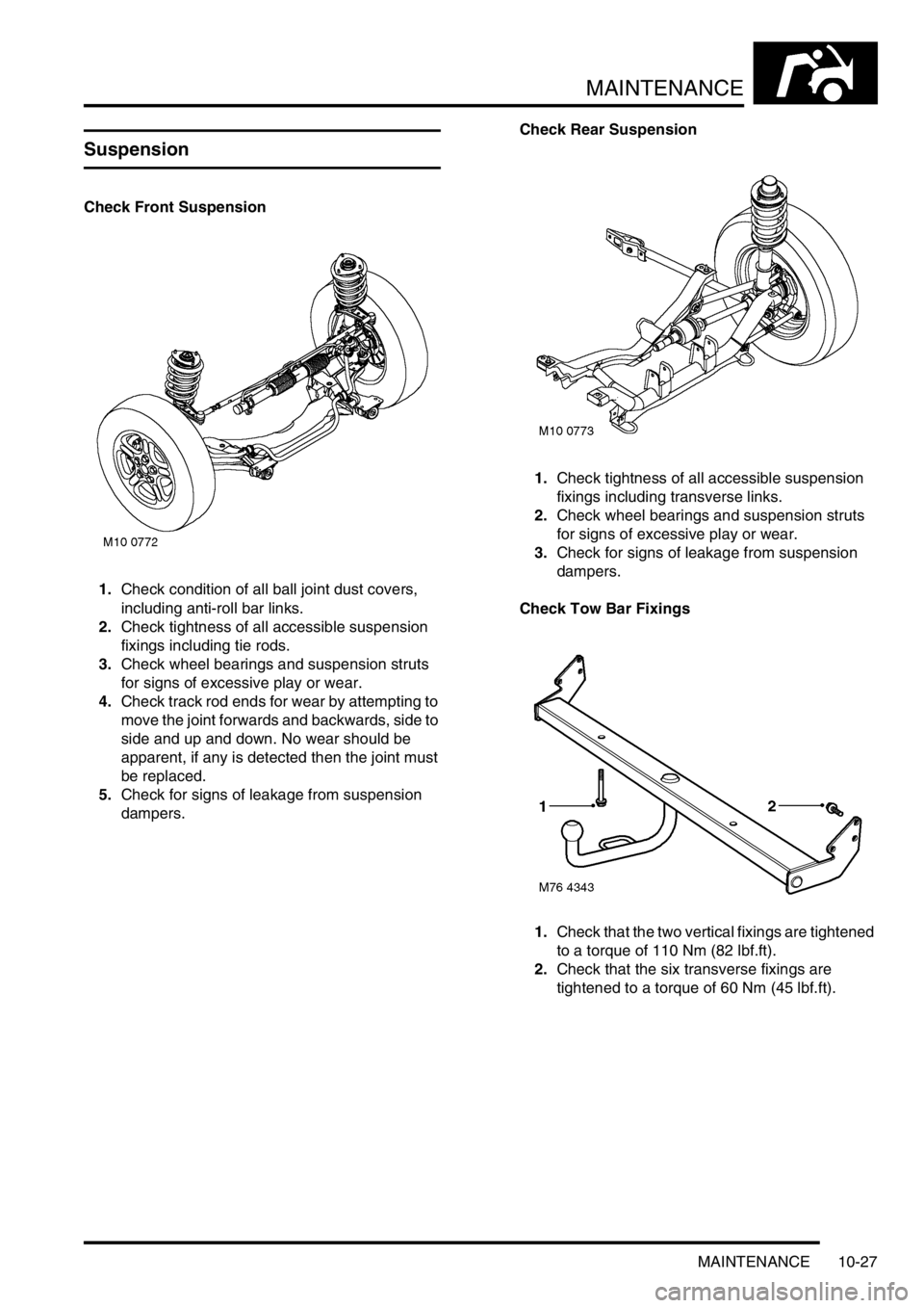
Check Front Suspension
1.Check condition of all ball joint dust covers,
including anti-roll bar links.
2.Check tightness of all accessible suspension
fixings including tie rods.
3.Check wheel bearings and suspension struts
for signs of excessive play or wear.
4.Check track rod ends for wear by attempting to
move the joint forwards and backwards, side to
side and up and down. No wear should be
apparent, if any is detected then the joint must
be replaced.
5.Check for signs of leakage from suspension
dampers.Check Rear Suspension
1.Check tightness of all accessible suspension
fixings including transverse links.
2.Check wheel bearings and suspension struts
for signs of excessive play or wear.
3.Check for signs of leakage from suspension
dampers.
Check Tow Bar Fixings
1.Check that the two vertical fixings are tightened
to a torque of 110 Nm (82 lbf.ft).
2.Check that the six transverse fixings are
tightened to a torque of 60 Nm (45 lbf.ft).
Page 516 of 1007
STEERING
REPAIRS 57-23
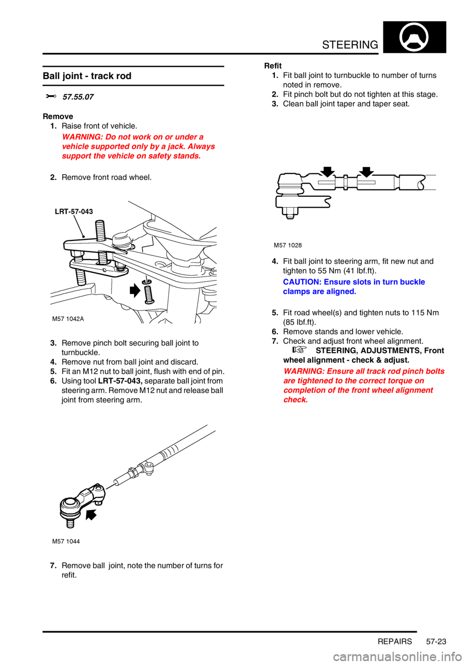
Ball joint - track rod
$% 57.55.07
Remove
1.Raise front of vehicle.
WARNING: Do not work on or under a
vehicle supported only by a jack. Always
support the vehicle on safety stands.
2.Remove front road wheel.
3.Remove pinch bolt securing ball joint to
turnbuckle.
4.Remove nut from ball joint and discard.
5.Fit an M12 nut to ball joint, flush with end of pin.
6.Using tool LRT-57-043, separate ball joint from
steering arm. Remove M12 nut and release ball
joint from steering arm.
7.Remove ball joint, note the number of turns for
refit.Refit
1.Fit ball joint to turnbuckle to number of turns
noted in remove.
2.Fit pinch bolt but do not tighten at this stage.
3.Clean ball joint taper and taper seat.
4.Fit ball joint to steering arm, fit new nut and
tighten to 55 Nm (41 lbf.ft).
CAUTION: Ensure slots in turn buckle
clamps are aligned.
5.Fit road wheel(s) and tighten nuts to 115 Nm
(85 lbf.ft).
6.Remove stands and lower vehicle.
7.Check and adjust front wheel alignment.
+ STEERING, ADJUSTMENTS, Front
wheel alignment - check & adjust.
WARNING: Ensure all track rod pinch bolts
are tightened to the correct torque on
completion of the front wheel alignment
check.
Page 517 of 1007
STEERING
57-24 REPAIRS
Track rod
$% 57.55.09
Remove
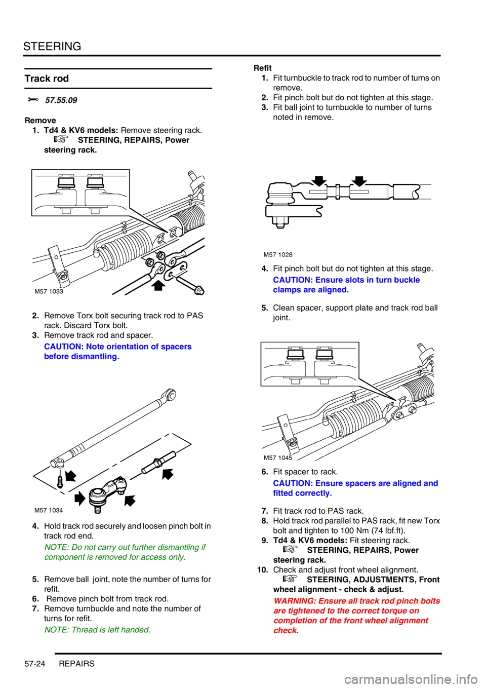
1. Td4 & KV6 models: Remove steering rack.
+ STEERING, REPAIRS, Power
steering rack.
2.Remove Torx bolt securing track rod to PAS
rack. Discard Torx bolt.
3.Remove track rod and spacer.
CAUTION: Note orientation of spacers
before dismantling.
4.Hold track rod securely and loosen pinch bolt in
track rod end.
NOTE: Do not carry out further dismantling if
component is removed for access only.
5.Remove ball joint, note the number of turns for
refit.
6. Remove pinch bolt from track rod.
7.Remove turnbuckle and note the number of
turns for refit.
NOTE: Thread is left handed.Refit
1.Fit turnbuckle to track rod to number of turns on
remove.
2.Fit pinch bolt but do not tighten at this stage.
3.Fit ball joint to turnbuckle to number of turns
noted in remove.
4.Fit pinch bolt but do not tighten at this stage.
CAUTION: Ensure slots in turn buckle
clamps are aligned.
5.Clean spacer, support plate and track rod ball
joint.
6.Fit spacer to rack.
CAUTION: Ensure spacers are aligned and
fitted correctly.
7.Fit track rod to PAS rack.
8.Hold track rod parallel to PAS rack, fit new Torx
bolt and tighten to 100 Nm (74 lbf.ft).
9. Td4 & KV6 models: Fit steering rack.
+ STEERING, REPAIRS, Power
steering rack.
10.Check and adjust front wheel alignment.
+ STEERING, ADJUSTMENTS, Front
wheel alignment - check & adjust.
WARNING: Ensure all track rod pinch bolts
are tightened to the correct torque on
completion of the front wheel alignment
check.