washer fluid LAND ROVER FREELANDER 2001 Owner's Manual
[x] Cancel search | Manufacturer: LAND ROVER, Model Year: 2001, Model line: FREELANDER, Model: LAND ROVER FREELANDER 2001Pages: 1007, PDF Size: 23.47 MB
Page 437 of 1007
AUTOMATIC GEARBOX - JATCO
44-2 ADJUSTMENTS
Gearbox fluid - drain & refill
$% 44.24.02
Drain
1.Position vehicle on ramp.
WARNING: Observe due care when draining
gearbox fluid as the fluid can be very hot.
2.Apply handbrake and position chocks under
front and rear wheels.
3.Remove underbelly panel.
+ EXTERIOR FITTINGS, REPAIRS,
Panel - underbelly.
4.Position container under gearbox.
NOTE: The fluid should be drained with the
transmission at normal operating temperature.
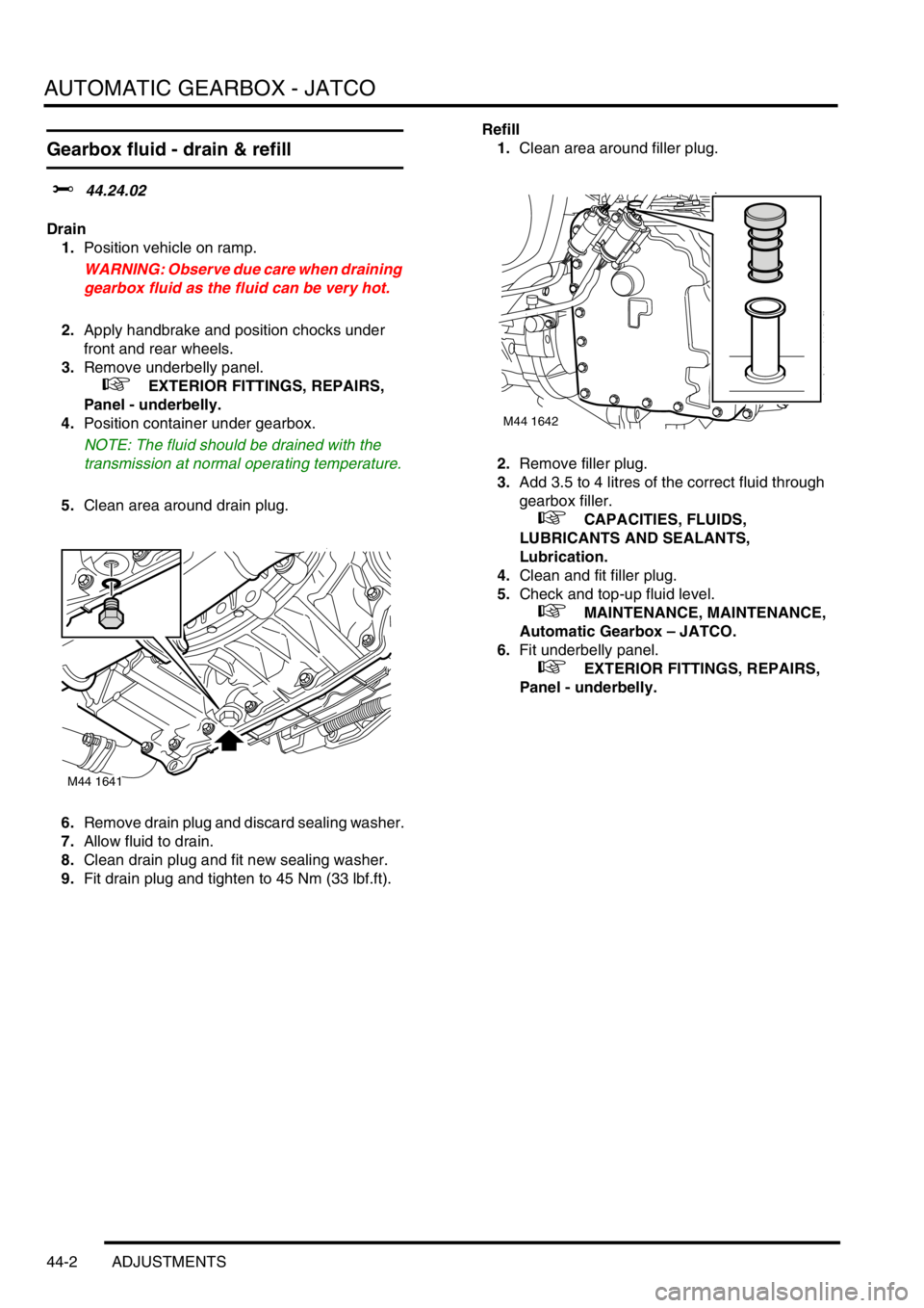
5.Clean area around drain plug.
6.Remove drain plug and discard sealing washer.
7.Allow fluid to drain.
8.Clean drain plug and fit new sealing washer.
9.Fit drain plug and tighten to 45 Nm (33 lbf.ft).Refill
1.Clean area around filler plug.
2.Remove filler plug.
3.Add 3.5 to 4 litres of the correct fluid through
gearbox filler.
+ CAPACITIES, FLUIDS,
LUBRICANTS AND SEALANTS,
Lubrication.
4.Clean and fit filler plug.
5.Check and top-up fluid level.
+ MAINTENANCE, MAINTENANCE,
Automatic Gearbox – JATCO.
6.Fit underbelly panel.
+ EXTERIOR FITTINGS, REPAIRS,
Panel - underbelly.
M44 1641
M44 1642
Page 499 of 1007
STEERING
57-6 REPAIRS
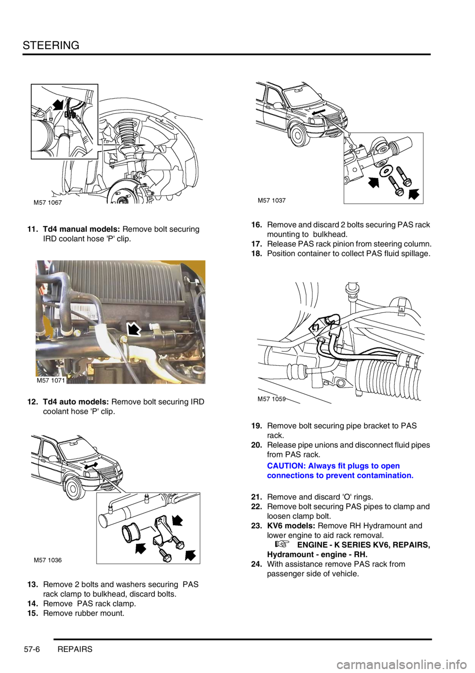
11. Td4 manual models: Remove bolt securing
IRD coolant hose 'P' clip.
12. Td4 auto models: Remove bolt securing IRD
coolant hose 'P' clip.
13.Remove 2 bolts and washers securing PAS
rack clamp to bulkhead, discard bolts.
14.Remove PAS rack clamp.
15.Remove rubber mount.16.Remove and discard 2 bolts securing PAS rack
mounting to bulkhead.
17.Release PAS rack pinion from steering column.
18.Position container to collect PAS fluid spillage.
19.Remove bolt securing pipe bracket to PAS
rack.
20.Release pipe unions and disconnect fluid pipes
from PAS rack.
CAUTION: Always fit plugs to open
connections to prevent contamination.
21.Remove and discard 'O' rings.
22.Remove bolt securing PAS pipes to clamp and
loosen clamp bolt.
23. KV6 models: Remove RH Hydramount and
lower engine to aid rack removal.
+ ENGINE - K SERIES KV6, REPAIRS,
Hydramount - engine - RH.
24.With assistance remove PAS rack from
passenger side of vehicle.
M57 1071
Page 500 of 1007
STEERING
REPAIRS 57-7
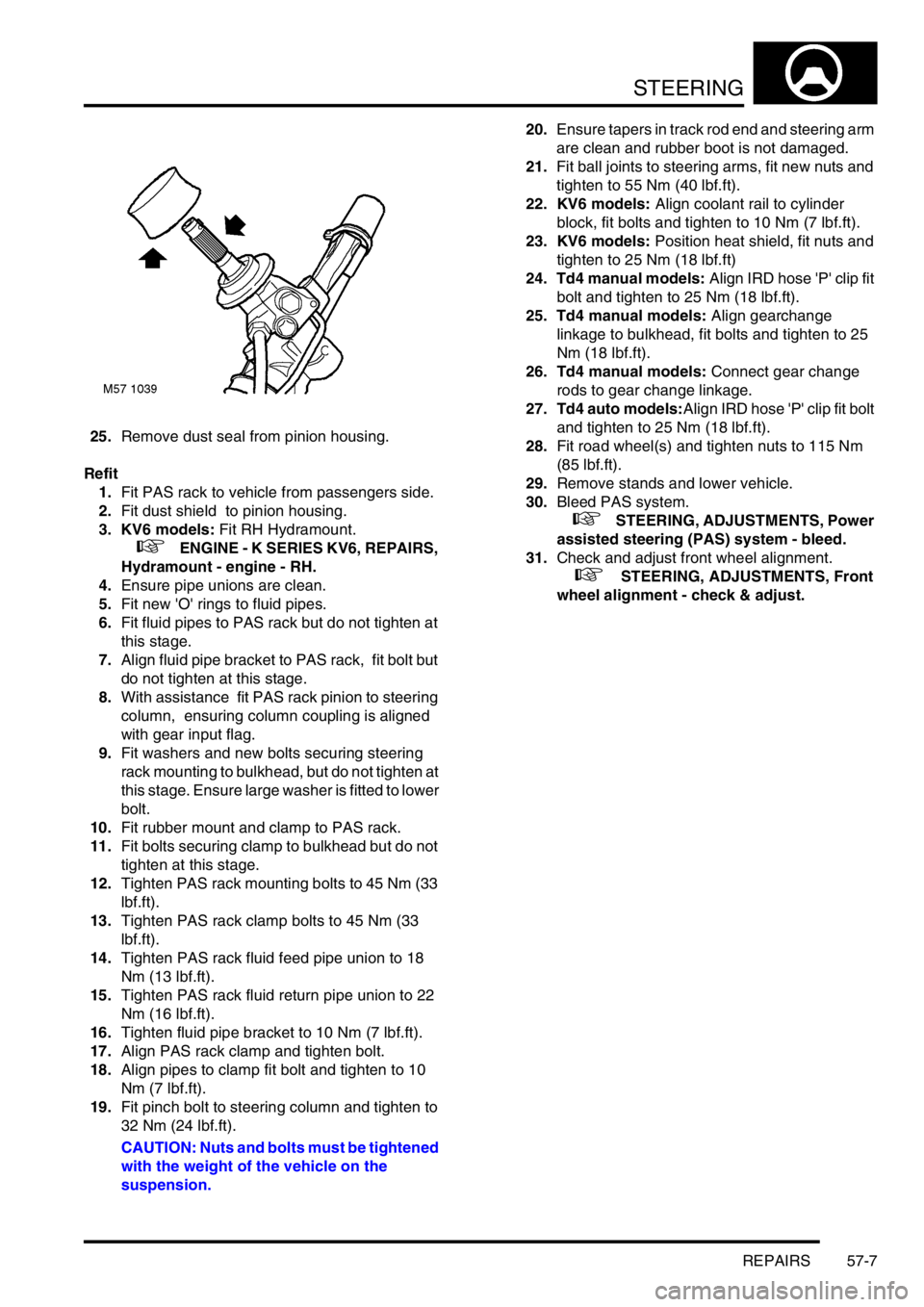
25.Remove dust seal from pinion housing.
Refit
1.Fit PAS rack to vehicle from passengers side.
2.Fit dust shield to pinion housing.
3. KV6 models: Fit RH Hydramount.
+ ENGINE - K SERIES KV6, REPAIRS,
Hydramount - engine - RH.
4.Ensure pipe unions are clean.
5.Fit new 'O' rings to fluid pipes.
6.Fit fluid pipes to PAS rack but do not tighten at
this stage.
7.Align fluid pipe bracket to PAS rack, fit bolt but
do not tighten at this stage.
8.With assistance fit PAS rack pinion to steering
column, ensuring column coupling is aligned
with gear input flag.
9.Fit washers and new bolts securing steering
rack mounting to bulkhead, but do not tighten at
this stage. Ensure large washer is fitted to lower
bolt.
10.Fit rubber mount and clamp to PAS rack.
11.Fit bolts securing clamp to bulkhead but do not
tighten at this stage.
12.Tighten PAS rack mounting bolts to 45 Nm (33
lbf.ft).
13.Tighten PAS rack clamp bolts to 45 Nm (33
lbf.ft).
14.Tighten PAS rack fluid feed pipe union to 18
Nm (13 lbf.ft).
15.Tighten PAS rack fluid return pipe union to 22
Nm (16 lbf.ft).
16.Tighten fluid pipe bracket to 10 Nm (7 lbf.ft).
17.Align PAS rack clamp and tighten bolt.
18.Align pipes to clamp fit bolt and tighten to 10
Nm (7 lbf.ft).
19.Fit pinch bolt to steering column and tighten to
32 Nm (24 lbf.ft).
CAUTION: Nuts and bolts must be tightened
with the weight of the vehicle on the
suspension.20.Ensure tapers in track rod end and steering arm
are clean and rubber boot is not damaged.
21.Fit ball joints to steering arms, fit new nuts and
tighten to 55 Nm (40 lbf.ft).
22. KV6 models: Align coolant rail to cylinder
block, fit bolts and tighten to 10 Nm (7 lbf.ft).
23. KV6 models: Position heat shield, fit nuts and
tighten to 25 Nm (18 lbf.ft)
24. Td4 manual models: Align IRD hose 'P' clip fit
bolt and tighten to 25 Nm (18 lbf.ft).
25. Td4 manual models: Align gearchange
linkage to bulkhead, fit bolts and tighten to 25
Nm (18 lbf.ft).
26. Td4 manual models: Connect gear change
rods to gear change linkage.
27. Td4 auto models:Align IRD hose 'P' clip fit bolt
and tighten to 25 Nm (18 lbf.ft).
28.Fit road wheel(s) and tighten nuts to 115 Nm
(85 lbf.ft).
29.Remove stands and lower vehicle.
30.Bleed PAS system.
+ STEERING, ADJUSTMENTS, Power
assisted steering (PAS) system - bleed.
31.Check and adjust front wheel alignment.
+ STEERING, ADJUSTMENTS, Front
wheel alignment - check & adjust.
Page 505 of 1007
STEERING
57-12 REPAIRS
Pump - steering - KV6
$% 57.20.14
Remove
1.Disconnect battery earth lead.
2.Remove engine mounting top arm.
+ ENGINE - K SERIES KV6, REPAIRS,
Arm assembly - engine mounting RH.
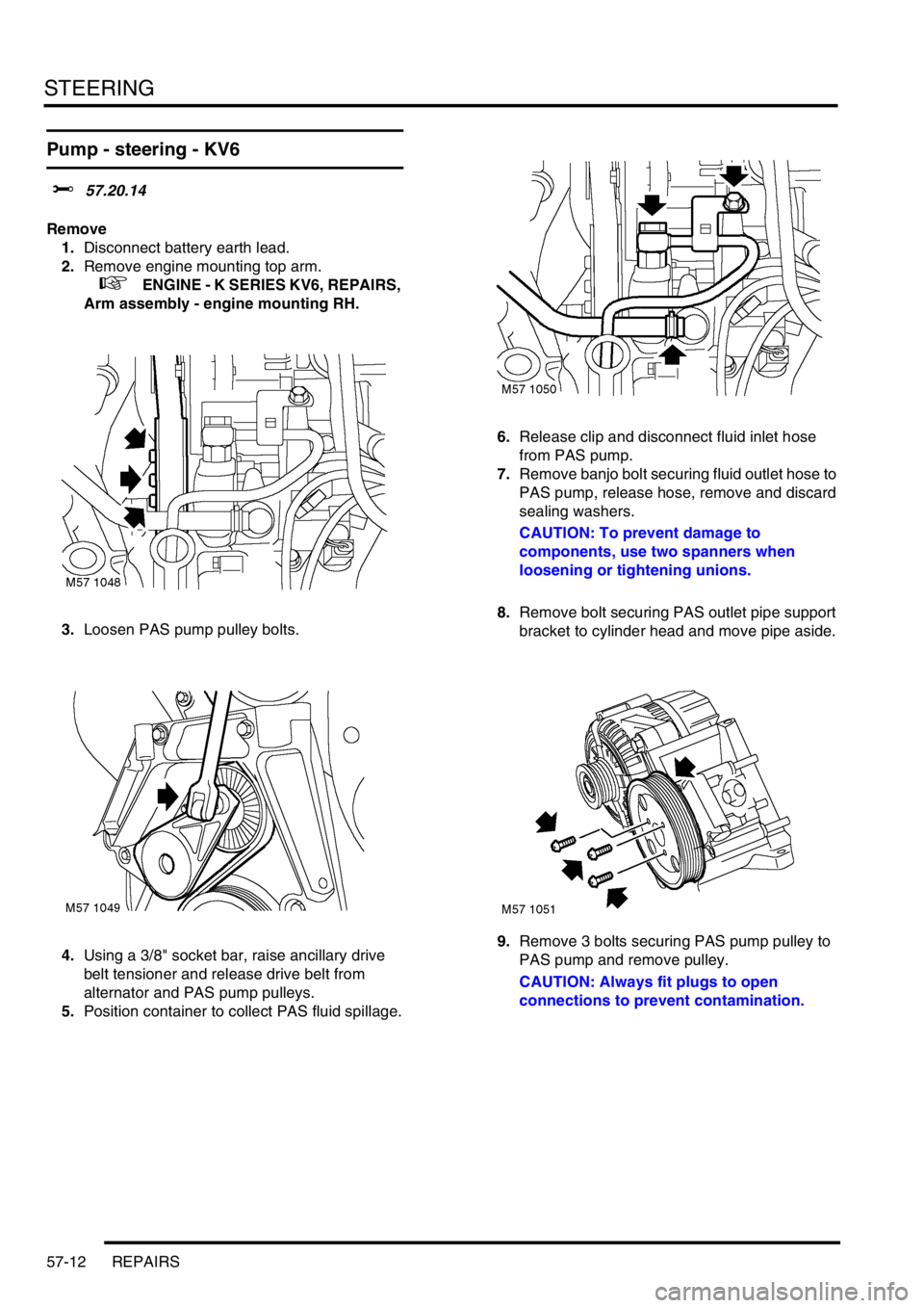
3.Loosen PAS pump pulley bolts.
4.Using a 3/8" socket bar, raise ancillary drive
belt tensioner and release drive belt from
alternator and PAS pump pulleys.
5.Position container to collect PAS fluid spillage.6.Release clip and disconnect fluid inlet hose
from PAS pump.
7.Remove banjo bolt securing fluid outlet hose to
PAS pump, release hose, remove and discard
sealing washers.
CAUTION: To prevent damage to
components, use two spanners when
loosening or tightening unions.
8.Remove bolt securing PAS outlet pipe support
bracket to cylinder head and move pipe aside.
9.Remove 3 bolts securing PAS pump pulley to
PAS pump and remove pulley.
CAUTION: Always fit plugs to open
connections to prevent contamination.
Page 506 of 1007
STEERING
REPAIRS 57-13
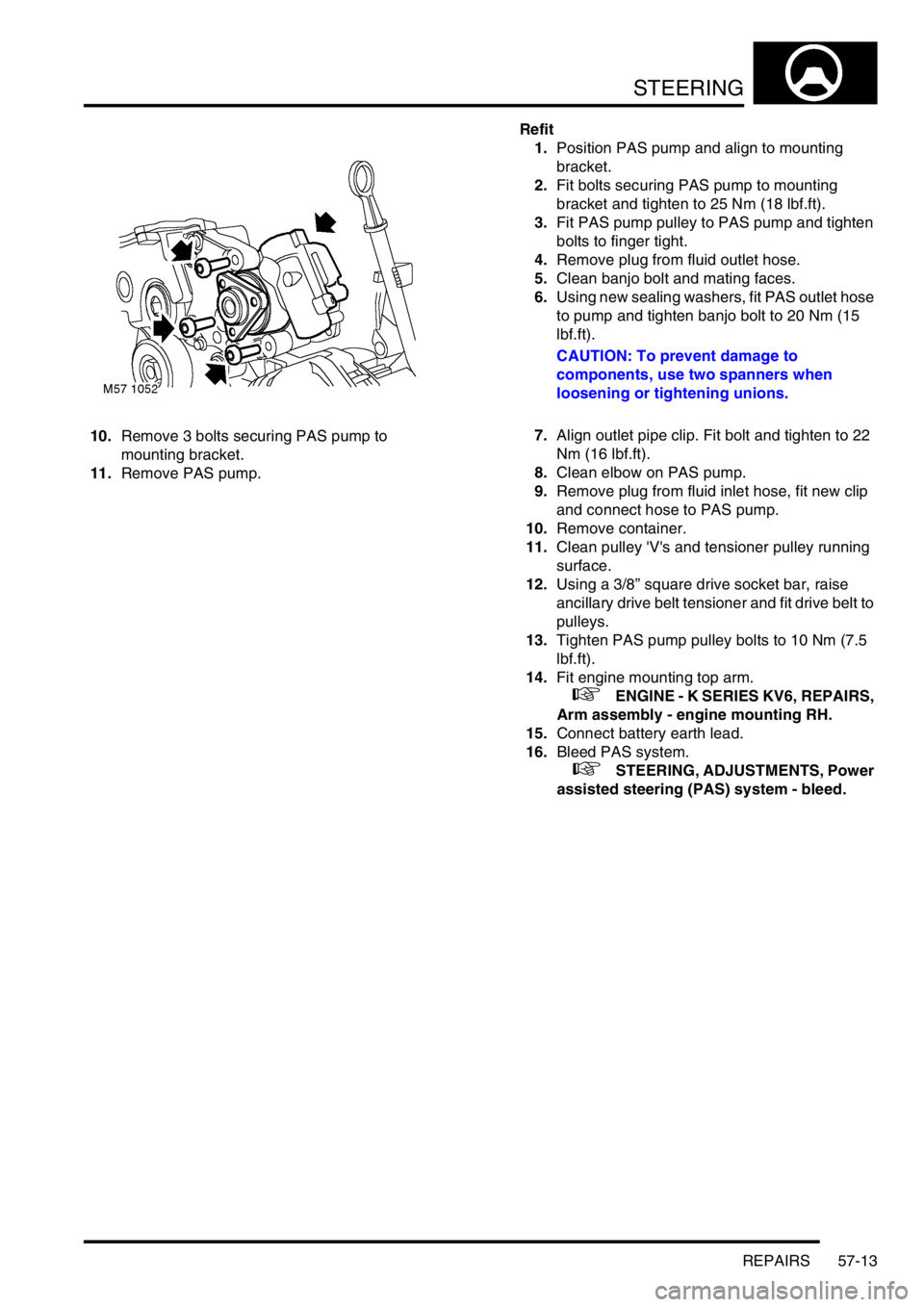
10.Remove 3 bolts securing PAS pump to
mounting bracket.
11.Remove PAS pump.Refit
1.Position PAS pump and align to mounting
bracket.
2.Fit bolts securing PAS pump to mounting
bracket and tighten to 25 Nm (18 lbf.ft).
3.Fit PAS pump pulley to PAS pump and tighten
bolts to finger tight.
4.Remove plug from fluid outlet hose.
5.Clean banjo bolt and mating faces.
6.Using new sealing washers, fit PAS outlet hose
to pump and tighten banjo bolt to 20 Nm (15
lbf.ft).
CAUTION: To prevent damage to
components, use two spanners when
loosening or tightening unions.
7.Align outlet pipe clip. Fit bolt and tighten to 22
Nm (16 lbf.ft).
8.Clean elbow on PAS pump.
9.Remove plug from fluid inlet hose, fit new clip
and connect hose to PAS pump.
10.Remove container.
11.Clean pulley 'V's and tensioner pulley running
surface.
12.Using a 3/8” square drive socket bar, raise
ancillary drive belt tensioner and fit drive belt to
pulleys.
13.Tighten PAS pump pulley bolts to 10 Nm (7.5
lbf.ft).
14.Fit engine mounting top arm.
+ ENGINE - K SERIES KV6, REPAIRS,
Arm assembly - engine mounting RH.
15.Connect battery earth lead.
16.Bleed PAS system.
+ STEERING, ADJUSTMENTS, Power
assisted steering (PAS) system - bleed.
Page 508 of 1007
STEERING
REPAIRS 57-15
Pump - steering - Td4
$% 57.20.14
Remove
1.Disconnect battery earth lead.
2.Remove hydramount.
+ ENGINE - Td4, REPAIRS,
Hydramount - engine - RH.
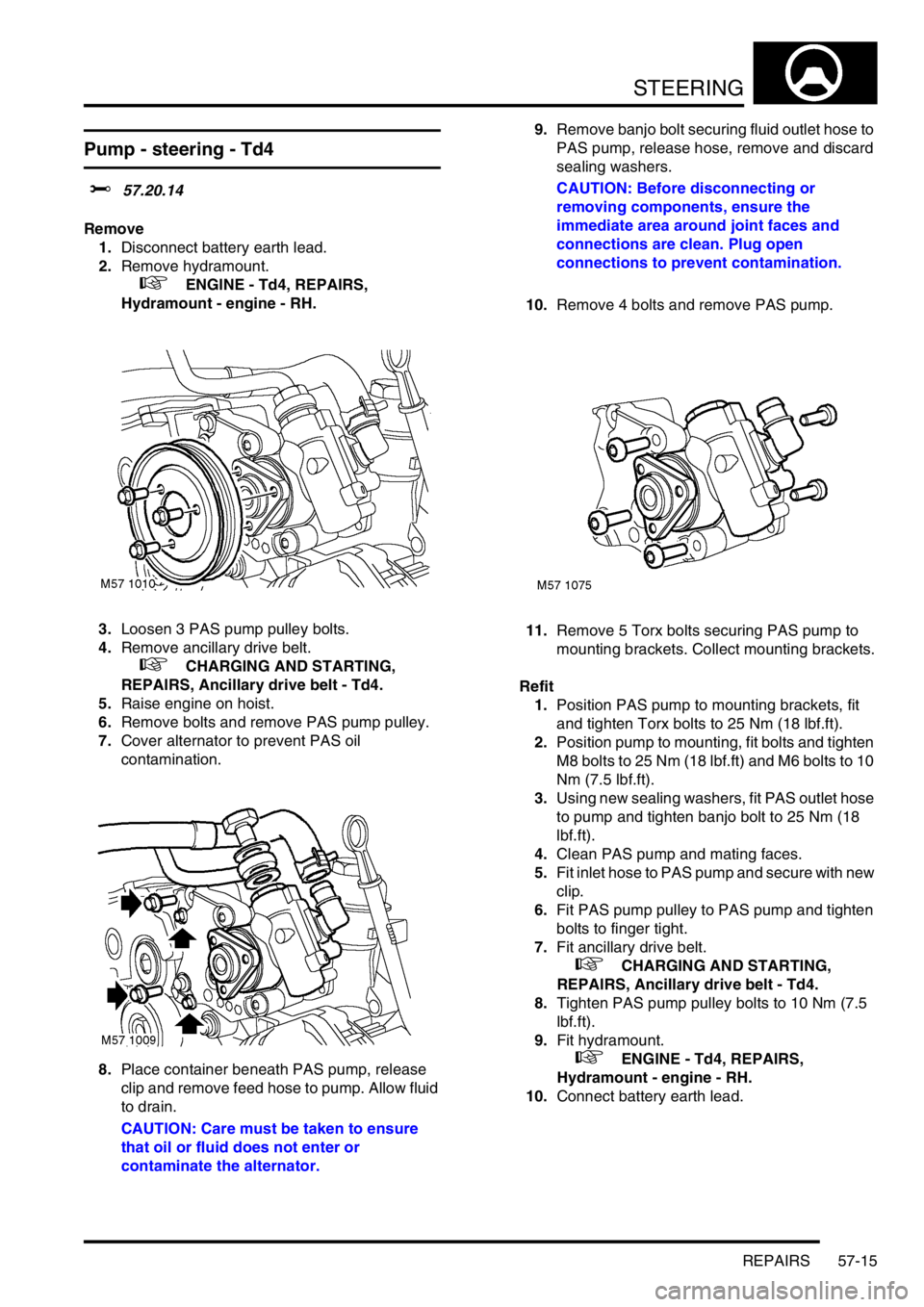
3.Loosen 3 PAS pump pulley bolts.
4.Remove ancillary drive belt.
+ CHARGING AND STARTING,
REPAIRS, Ancillary drive belt - Td4.
5.Raise engine on hoist.
6.Remove bolts and remove PAS pump pulley.
7.Cover alternator to prevent PAS oil
contamination.
8.Place container beneath PAS pump, release
clip and remove feed hose to pump. Allow fluid
to drain.
CAUTION: Care must be taken to ensure
that oil or fluid does not enter or
contaminate the alternator.9.Remove banjo bolt securing fluid outlet hose to
PAS pump, release hose, remove and discard
sealing washers.
CAUTION: Before disconnecting or
removing components, ensure the
immediate area around joint faces and
connections are clean. Plug open
connections to prevent contamination.
10.Remove 4 bolts and remove PAS pump.
11.Remove 5 Torx bolts securing PAS pump to
mounting brackets. Collect mounting brackets.
Refit
1.Position PAS pump to mounting brackets, fit
and tighten Torx bolts to 25 Nm (18 lbf.ft).
2.Position pump to mounting, fit bolts and tighten
M8 bolts to 25 Nm (18 lbf.ft) and M6 bolts to 10
Nm (7.5 lbf.ft).
3.Using new sealing washers, fit PAS outlet hose
to pump and tighten banjo bolt to 25 Nm (18
lbf.ft).
4.Clean PAS pump and mating faces.
5.Fit inlet hose to PAS pump and secure with new
clip.
6.Fit PAS pump pulley to PAS pump and tighten
bolts to finger tight.
7.Fit ancillary drive belt.
+ CHARGING AND STARTING,
REPAIRS, Ancillary drive belt - Td4.
8.Tighten PAS pump pulley bolts to 10 Nm (7.5
lbf.ft).
9.Fit hydramount.
+ ENGINE - Td4, REPAIRS,
Hydramount - engine - RH.
10.Connect battery earth lead.
Page 540 of 1007

REAR SUSPENSION
REPAIRS 64-5
7.Fit hub to damper and tighten bolts to 205 Nm
(151 lbf.ft).
CAUTION: Nuts and bolts must be tightened
with weight of vehicle on suspension.
8.Fit nut, bolt and washers securing transverse
links to hub and tighten nut to 105 Nm (77 lbf.ft).
9.Fit trailing link to hub and tighten nut and bolt to
120 Nm (89 lbf.ft).
NOTE: Ensure that washers are fitted to both
ends of bolts
10.Clean ABS sensor, smear sensor with an anti-
seize grease and fit sensor to hub.
CAUTION: Ensure ABS sensor is fully
located into hub, so that sensor touches
pole wheel teeth.
11.Fit brake pipe to wheel cylinder and tighten
union to 14 Nm (10 lbf.ft).
12.Fit clip securing brakepipe to bracket.
13.Fit and secure handbrake cable to backplate.
14.Fit brake shoes.
+ BRAKES, REPAIRS, Brake Shoes -
rear set.
15.Fit new drive shaft nut and tighten to 400 Nm
(295 lbf.ft). Stake nut to shaft.
16.Bleed brakes.
+ BRAKES, ADJUSTMENTS, Brake
bleed.
17.Fit road wheel(s) and tighten nuts to 115 Nm
(85 lbf.ft).
18.Remove stands and lower vehicle.
Damper
$% 64.30.02
Remove
1.Raise rear of vehicle.
WARNING: Do not work on or under a
vehicle supported only by a jack. Always
support the vehicle on safety stands.
2.Remove road wheel.
3.Clamp brake hose to prevent fluid loss.
4.Position absorbent cloth to catch spillage.
5.Loosen brake pipe union to hose and release
union.
CAUTION: Always fit plugs to open
connections to prevent contamination.
6.Remove clip securing brake hose to bracket on
damper. Release brake hose from bracket.
7.Release ABS sensor harness and brake hose
from damper.
8.Release ABS sensor from hub.
Page 579 of 1007
BRAKES
70-30 REPAIRS
Modulator unit
$% 70.65.49
Remove
1. Td4 and KV6 models: Remove engine
accoustic cover if fitted.
+ ENGINE - Td4, REPAIRS, Cover -
engine acoustic - Up to 02.5 Model Year.
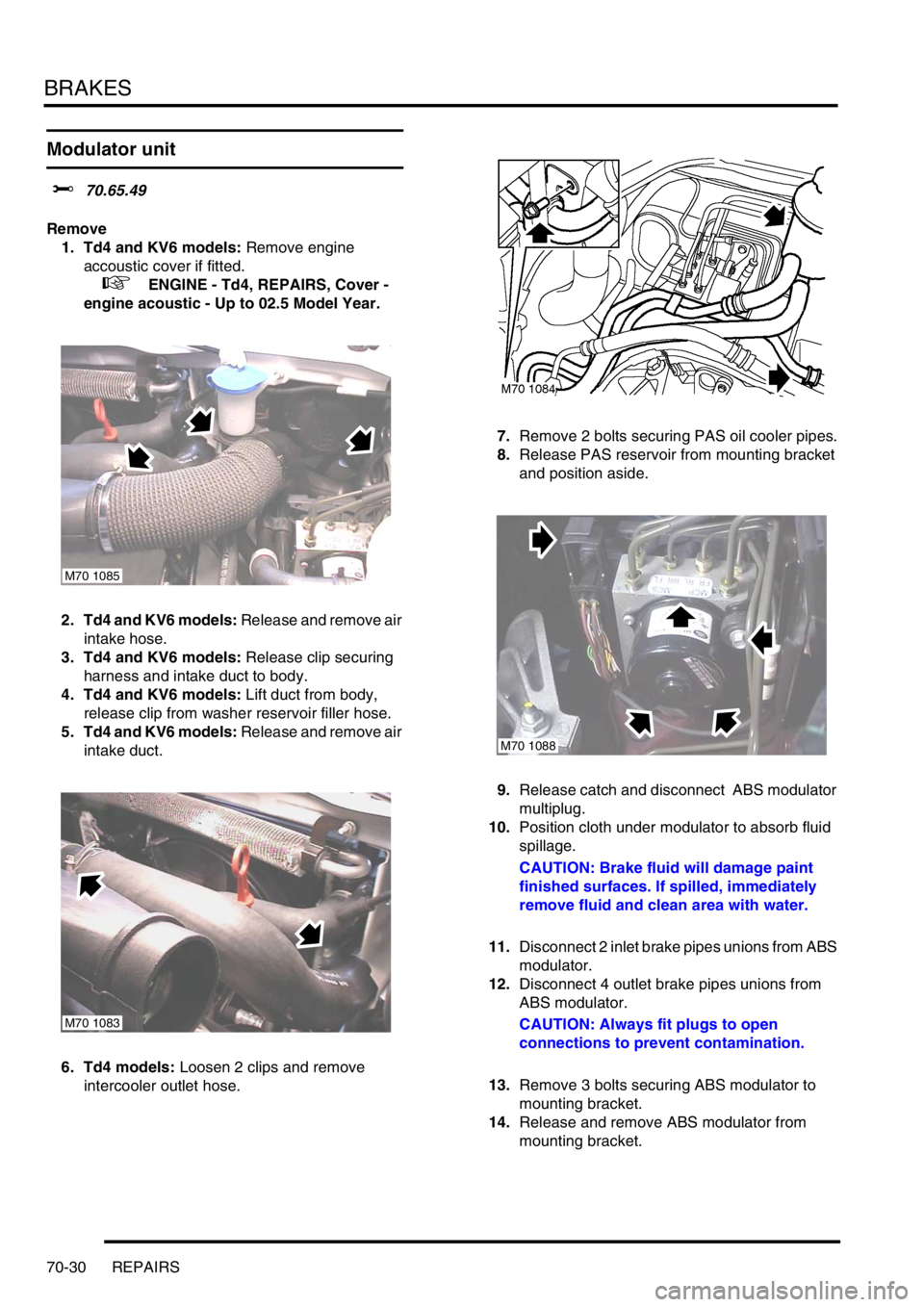
2. Td4 and KV6 models: Release and remove air
intake hose.
3. Td4 and KV6 models: Release clip securing
harness and intake duct to body.
4. Td4 and KV6 models: Lift duct from body,
release clip from washer reservoir filler hose.
5. Td4 and KV6 models: Release and remove air
intake duct.
6. Td4 models: Loosen 2 clips and remove
intercooler outlet hose.7.Remove 2 bolts securing PAS oil cooler pipes.
8.Release PAS reservoir from mounting bracket
and position aside.
9.Release catch and disconnect ABS modulator
multiplug.
10.Position cloth under modulator to absorb fluid
spillage.
CAUTION: Brake fluid will damage paint
finished surfaces. If spilled, immediately
remove fluid and clean area with water.
11.Disconnect 2 inlet brake pipes unions from ABS
modulator.
12.Disconnect 4 outlet brake pipes unions from
ABS modulator.
CAUTION: Always fit plugs to open
connections to prevent contamination.
13.Remove 3 bolts securing ABS modulator to
mounting bracket.
14.Release and remove ABS modulator from
mounting bracket.
M70 1085
M70 1083
M70 1088
Page 756 of 1007
PANEL REPAIRS
BODY REPAIRS 77-2-1
PANEL REPAIRS
General
Body shells are of monocoque construction. Front and rear sections of the shell are designed as 'energy absorbing'
zones. This means they are designed to deform progressively when subjected to impact in order to minimise the
likelihood of injury to vehicle occupants.
It is essential that design dimensions and strength are restored in accident rectification. It is important that neither
structural weakness nor excessive local stiffness are introduced into the vehicle during body repair.
Repairs usually involve a combination of operations ranging from straightening procedures to renewal of individual
panels or panel assemblies. The repairer will determine the repair method and this decision will take into account a
balance of economics between labour and material costs and the availability of repair facilities in both equipment and
skills. It may also involve considerations of the vehicles' downtime, replacement vehicle availability and repair turn-
around time.
It is expected that a repairer will select the best and most economic repair method possible, making use of the facilities
available. The instructions given are intended to assist a skilled body repairer by expanding approved procedures for
panel replacement. The objective is to restore the vehicle to a safe running condition by carrying out a repair which is
as close as is feasible to original standard. The results should not advertise to the experienced eye that the vehicle
has been damaged, although the repair might not be identical in all respects to the original factory build. Commercial
bodyshop repair facilities cannot always duplicate methods of construction used during production.
Operations covered in this Manual do not include reference to testing the vehicle after repair. It is essential that work
is inspected and suspension geometry checked after completion. Where necessary a road test of the vehicle should
be carried out, particularly where safety-related items are concerned.
Where major units have been disconnected or removed it is necessary to ensure that fluid levels are checked and
topped up where necessary. It is also necessary to ensure that the repaired vehicle is in a roadworthy condition in
respect of tyre pressures, lights, washer fluid etc.
Body repairs often involve the removal of mechanical and electrical units and associated wiring. Where necessary,
refer to the relevant section of the Workshop Manual for removal and refitting instructions.
Body components
Taking into consideration the differences in body styles, suspension systems and engine and transmission layouts,
the location of the following components as applicable to a particular vehicle is critical:
lFront suspension upper damper mountings.
lFront suspension or sub frame mountings.
lRear suspension upper damper mountings.
lRear suspension mountings or lower pivots.
Additional points which can be used to check alignment and assembly are:
lInner holes in crossmember - side - main floor.
lHoles in front longitudinals.
lHoles in side members.
lHoles in rear longitudinals.
lHoles in rear lower panels or extension rear floor.
Apertures for windscreen, backlight, bonnet and doors can be measured and checked using the dimensional
information provided and also by offering up an undamaged component as a gauge.
Straightening
Whenever possible, structural members should be cold straightened under tension. Do not attempt to straighten with
a single pull but rework the damaged area using a series of pulls, releasing tension between each stage and using
the opportunity to check alignment.
Page 780 of 1007
PANEL REPAIRS
REPAIRS 77-2-25
REPAIRS
Front bulkhead assembly
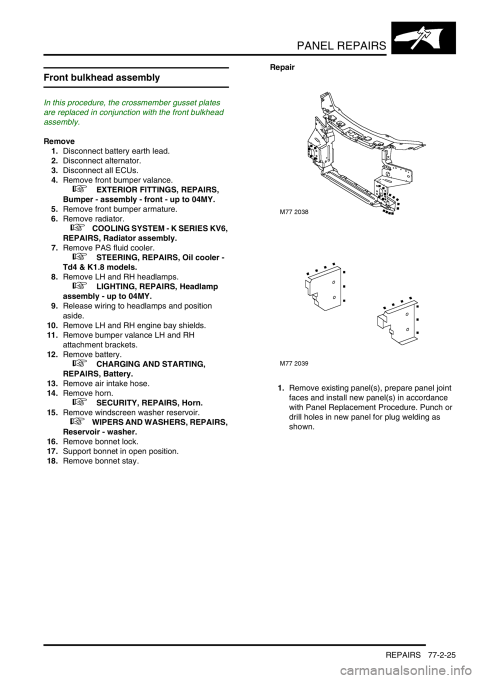
In this procedure, the crossmember gusset plates
are replaced in conjunction with the front bulkhead
assembly.
Remove
1.Disconnect battery earth lead.
2.Disconnect alternator.
3.Disconnect all ECUs.
4.Remove front bumper valance.
+ EXTERIOR FITTINGS, REPAIRS,
Bumper - assembly - front - up to 04MY.
5.Remove front bumper armature.
6.Remove radiator.
+ COOLING SYSTEM - K SERIES KV6,
REPAIRS, Radiator assembly.
7.Remove PAS fluid cooler.
+ STEERING, REPAIRS, Oil cooler -
Td4 & K1.8 models.
8.Remove LH and RH headlamps.
+ LIGHTING, REPAIRS, Headlamp
assembly - up to 04MY.
9.Release wiring to headlamps and position
aside.
10.Remove LH and RH engine bay shields.
11.Remove bumper valance LH and RH
attachment brackets.
12.Remove battery.
+ CHARGING AND STARTING,
REPAIRS, Battery.
13.Remove air intake hose.
14.Remove horn.
+ SECURITY, REPAIRS, Horn.
15.Remove windscreen washer reservoir.
+ WIPERS AND WASHERS, REPAIRS,
Reservoir - washer.
16.Remove bonnet lock.
17.Support bonnet in open position.
18.Remove bonnet stay. Repair
1.Remove existing panel(s), prepare panel joint
faces and install new panel(s) in accordance
with Panel Replacement Procedure. Punch or
drill holes in new panel for plug welding as
shown.