wheel LAND ROVER FREELANDER 2001 Service Manual
[x] Cancel search | Manufacturer: LAND ROVER, Model Year: 2001, Model line: FREELANDER, Model: LAND ROVER FREELANDER 2001Pages: 1007, PDF Size: 23.47 MB
Page 166 of 1007
MAINTENANCE
MAINTENANCE 10-19
Manual Gearbox – GETRAG
Replace Fluid
WARNING: Avoid excessive skin contact
with mineral oil. Mineral oils remove the
natural fats from the skin, leading to
dryness, irritation and dermatitis.
1.Replace gearbox fluid.
+ MANUAL GEARBOX - GETRAG,
ADJUSTMENTS, Gearbox oil - drain and
refill.
Automatic Gearbox – JATCO
Check and top-up fluid
WARNING: Avoid excessive skin contact
with mineral oil. Mineral oils remove the
natural fats from the skin, leading to
dryness, irritation and dermatitis.
1.Position vehicle on ramp.
2.Apply handbrake and position chocks under
front and rear wheels.
3.Remove underbelly panel.
+ EXTERIOR FITTINGS, REPAIRS,
Panel - underbelly.
4.Connect TestBook/T4 to monitor gearbox fluid
temperature.
CAUTION: The gearbox fluid level must only
be checked when the temperature of the
fluid is between 35° and 45°. The reading
obtained will be incorrect if the fluid is
outside this temperature range.
5.Start engine, move selector lever from 'P'
through all gear positions, pausing in each gear
position for 2-3 seconds and return to 'P'
position.
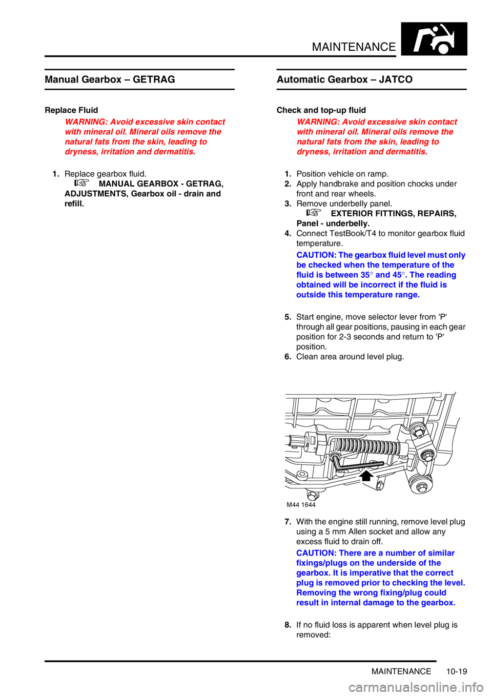
6.Clean area around level plug.
7.With the engine still running, remove level plug
using a 5 mm Allen socket and allow any
excess fluid to drain off.
CAUTION: There are a number of similar
fixings/plugs on the underside of the
gearbox. It is imperative that the correct
plug is removed prior to checking the level.
Removing the wrong fixing/plug could
result in internal damage to the gearbox.
8.If no fluid loss is apparent when level plug is
removed:
Page 174 of 1007
MAINTENANCE
MAINTENANCE 10-27
Suspension
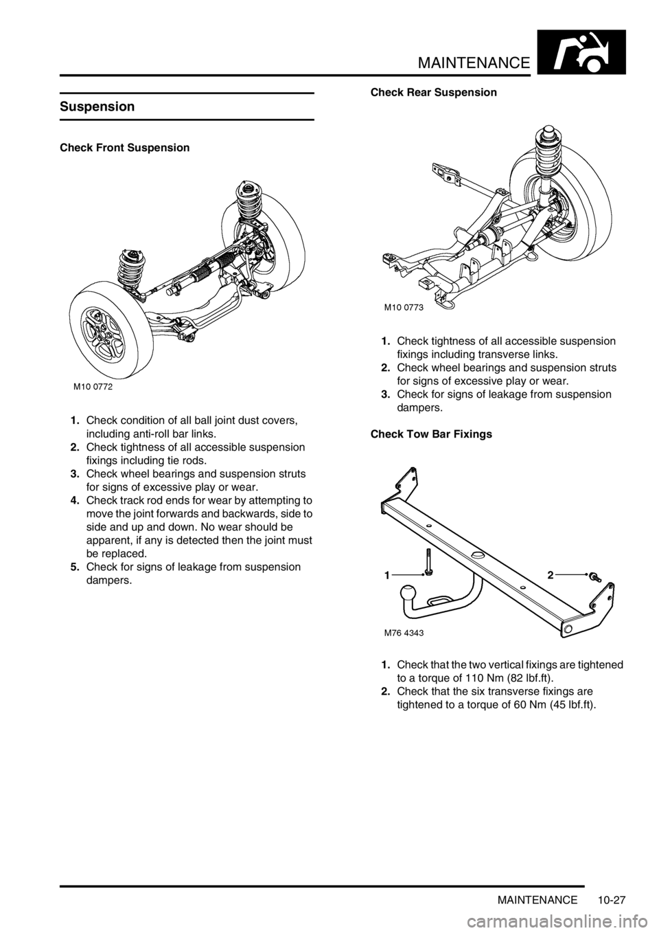
Check Front Suspension
1.Check condition of all ball joint dust covers,
including anti-roll bar links.
2.Check tightness of all accessible suspension
fixings including tie rods.
3.Check wheel bearings and suspension struts
for signs of excessive play or wear.
4.Check track rod ends for wear by attempting to
move the joint forwards and backwards, side to
side and up and down. No wear should be
apparent, if any is detected then the joint must
be replaced.
5.Check for signs of leakage from suspension
dampers.Check Rear Suspension
1.Check tightness of all accessible suspension
fixings including transverse links.
2.Check wheel bearings and suspension struts
for signs of excessive play or wear.
3.Check for signs of leakage from suspension
dampers.
Check Tow Bar Fixings
1.Check that the two vertical fixings are tightened
to a torque of 110 Nm (82 lbf.ft).
2.Check that the six transverse fixings are
tightened to a torque of 60 Nm (45 lbf.ft).
Page 175 of 1007
MAINTENANCE
10-28 MAINTENANCE
Steering
Check
1.Check/tighten steering unit and steering rod
ball joint fixings.
2.Check condition of ball joints and dust covers.
3.Check steering rack bellows for any signs of
leakage.
Road Test
There are two purposes for conducting a road test.
Firstly, to ensure the work completed within the
dealership meets the standards required as laid
down by dealership processes. Secondly, for a
skilled technician to assess the general condition of
the vehicle and report any conditions that the
customer should be made aware of.
CAUTION: Two wheel dynamometer tests must
not be carried out. Four wheel dynamometer
tests must be restricted to 3 mph (5 kph).
Engine Start
1.Check for correct operation of starter switch.
Ensure the engine starts in a correct manner.
Leave the engine running.
Starter Inhibitor Switch – (Automatic only)
1.Select 'D' gear lever position.
2.Check that engine will not start.
3.Select 'R' gear lever position and repeat start
check.
4.Check that engine will start in 'P' and 'N'
positions.
Selector Cable – (Automatic only)
1.Check for correct setting of gear selector cable.
Engine Performance and Throttle Operation
1.Start engine and check that it starts easily.
2.Check that 'oil pressure' and 'no charge'
warning lamps extinguish.
3.Check that throttle pedal movement is free and
unrestricted.
4.Check that engine is responsive to throttle
movement.
Clutch and Gear Selection –
(Manual only, normal driving conditions)
1.Check that clutch engages smoothly without
judder, slipping or noise.
2.Check for abnormal transmission noise.
3.Check for smooth quiet gear changes and that
gear selected engages easily.
Page 176 of 1007

MAINTENANCE
MAINTENANCE 10-29
Gear Change and Parking Pawl Engagement –
(Automatic only, normal driving conditions)
1.Select 'R' and check for smooth take up.
2.Select 'D' and check for smooth up-changes of
ratio from rest.
3.Slow down vehicle and check for smooth down-
changes of ratio.
4.Stop vehicle on a slope.
5.Select 'P' and release handbrake.
6.Check that vehicle does not move and that
selector does not slip out of 'P'.
7.Carry out a similar check with vehicle facing in
the opposite direction.
Steering
1.With vehicle stationary, turn steering from lock
to lock. Check for smooth operation and ensure
there is no undue noise from the power steering
pump or drive belt.
Suspension
1.Check for noise, irregularity in ride (e.g.
dampers) and wheel imbalance.
Foot brake
1.Check for pedal effort, travel, braking
efficiency, pulling and binding.
Handbrake
1.Apply handbrake firmly, check travel and
ratchet hold and release.
Instruments
1.Check for correct operation of all instruments
and warning devices where practical.
Body
1.Check for abnormal body noise.
Seat Belts
1.Check for operation of inertia reels.Road Test
1.Drive vehicle on a short road test. Check all
vehicle systems for correct operation. Pay
particular attention to:
lEngine noise
lGearbox noise
lSuspension noise
lBody noise
lBraking system operation
lGear selection
lEngine performance
2.Where possible, check for correct operation of
Hill Descent Control (HDC) system. This should
not be carried out if excessive journey time is
required.
3.After road test, carry out a final inspection of the
vehicle on vehicle ramps.
4.Check all underbonnet fluid levels and top-up if
necessary.
Page 187 of 1007
ENGINE - K SERIES KV6
12-3-10 REPAIRS
Pulley - crankshaft
$% 12.21.01
Remove
1.Remove underbelly panel.
+ EXTERIOR FITTINGS, REPAIRS,
Panel - underbelly.
2.Remove RH front road wheel.
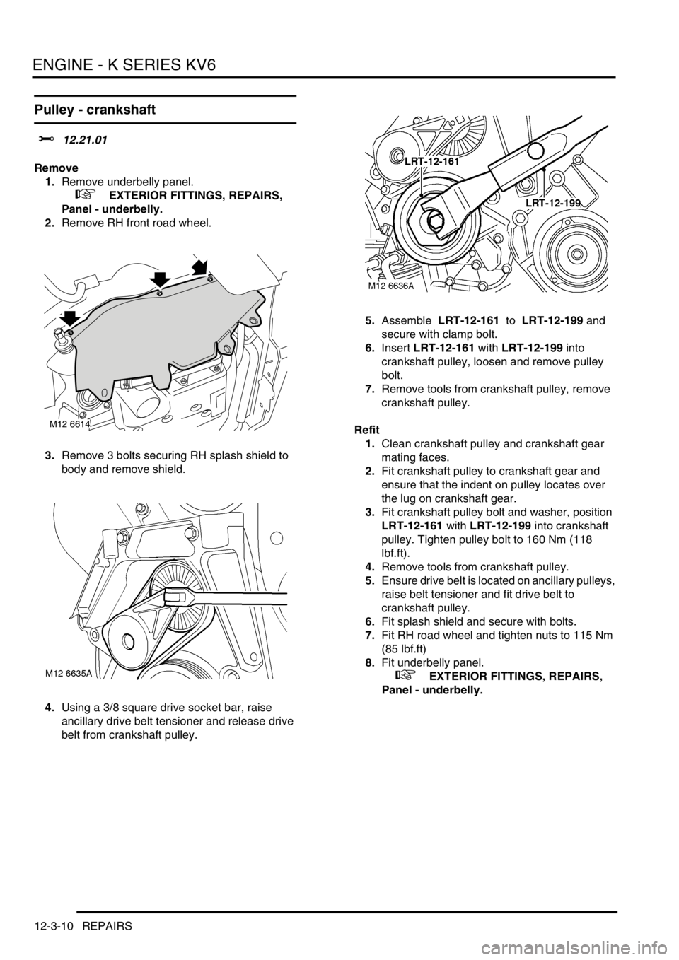
3.Remove 3 bolts securing RH splash shield to
body and remove shield.
4.Using a 3/8 square drive socket bar, raise
ancillary drive belt tensioner and release drive
belt from crankshaft pulley.5.Assemble LRT-12-161 to LRT-12-199 and
secure with clamp bolt.
6.Insert LRT-12-161 with LRT-12-199 into
crankshaft pulley, loosen and remove pulley
bolt.
7.Remove tools from crankshaft pulley, remove
crankshaft pulley.
Refit
1.Clean crankshaft pulley and crankshaft gear
mating faces.
2.Fit crankshaft pulley to crankshaft gear and
ensure that the indent on pulley locates over
the lug on crankshaft gear.
3.Fit crankshaft pulley bolt and washer, position
LRT-12-161 with LRT-12-199 into crankshaft
pulley. Tighten pulley bolt to 160 Nm (118
lbf.ft).
4.Remove tools from crankshaft pulley.
5.Ensure drive belt is located on ancillary pulleys,
raise belt tensioner and fit drive belt to
crankshaft pulley.
6.Fit splash shield and secure with bolts.
7.Fit RH road wheel and tighten nuts to 115 Nm
(85 lbf.ft)
8.Fit underbelly panel.
+ EXTERIOR FITTINGS, REPAIRS,
Panel - underbelly.
M12 6614
Page 205 of 1007
ENGINE - K SERIES KV6
12-3-28 REPAIRS
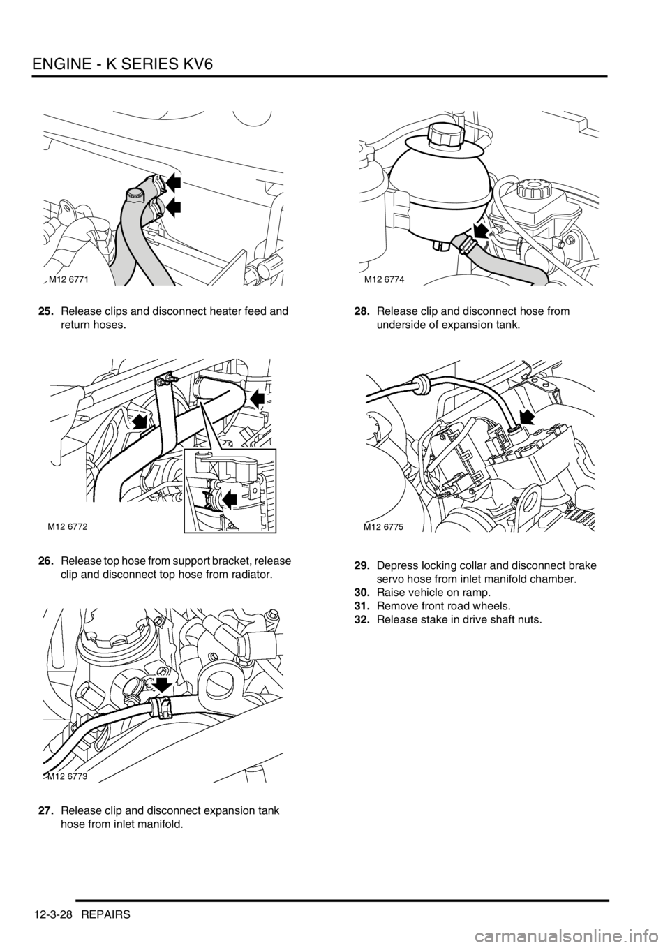
25.Release clips and disconnect heater feed and
return hoses.
26.Release top hose from support bracket, release
clip and disconnect top hose from radiator.
27.Release clip and disconnect expansion tank
hose from inlet manifold.28.Release clip and disconnect hose from
underside of expansion tank.
29.Depress locking collar and disconnect brake
servo hose from inlet manifold chamber.
30.Raise vehicle on ramp.
31.Remove front road wheels.
32.Release stake in drive shaft nuts.
M12 6771M12 6774
Page 206 of 1007
ENGINE - K SERIES KV6
REPAIRS 12-3-29
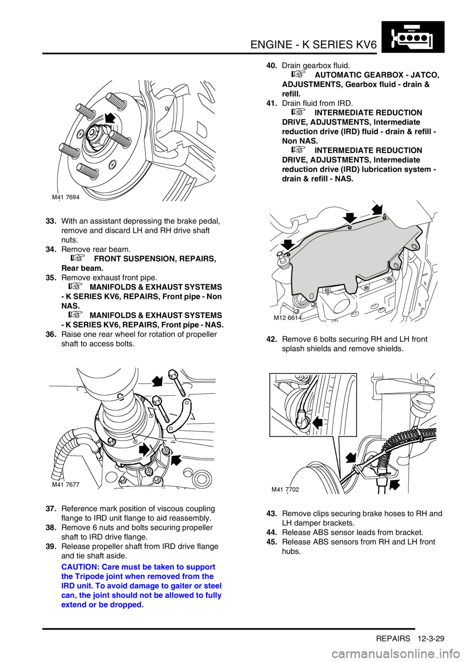
33.With an assistant depressing the brake pedal,
remove and discard LH and RH drive shaft
nuts.
34.Remove rear beam.
+ FRONT SUSPENSION, REPAIRS,
Rear beam.
35.Remove exhaust front pipe.
+ MANIFOLDS & EXHAUST SYSTEMS
- K SERIES KV6, REPAIRS, Front pipe - Non
NAS.
+ MANIFOLDS & EXHAUST SYSTEMS
- K SERIES KV6, REPAIRS, Front pipe - NAS.
36.Raise one rear wheel for rotation of propeller
shaft to access bolts.
37.Reference mark position of viscous coupling
flange to IRD unit flange to aid reassembly.
38.Remove 6 nuts and bolts securing propeller
shaft to IRD drive flange.
39.Release propeller shaft from IRD drive flange
and tie shaft aside.
CAUTION: Care must be taken to support
the Tripode joint when removed from the
IRD unit. To avoid damage to gaiter or steel
can, the joint should not be allowed to fully
extend or be dropped.40.Drain gearbox fluid.
+ AUTOMATIC GEARBOX - JATCO,
ADJUSTMENTS, Gearbox fluid - drain &
refill.
41.Drain fluid from IRD.
+ INTERMEDIATE REDUCTION
DRIVE, ADJUSTMENTS, Intermediate
reduction drive (IRD) fluid - drain & refill -
Non NAS.
+ INTERMEDIATE REDUCTION
DRIVE, ADJUSTMENTS, Intermediate
reduction drive (IRD) lubrication system -
drain & refill - NAS.
42.Remove 6 bolts securing RH and LH front
splash shields and remove shields.
43.Remove clips securing brake hoses to RH and
LH damper brackets.
44.Release ABS sensor leads from bracket.
45.Release ABS sensors from RH and LH front
hubs.
M12 6614
Page 210 of 1007
ENGINE - K SERIES KV6
REPAIRS 12-3-33
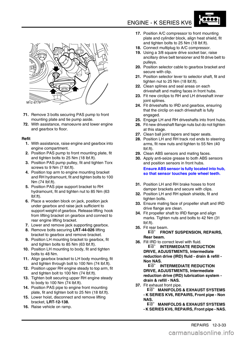
71.Remove 3 bolts securing PAS pump to front
mounting plate and tie pump aside.
72.With assistance, manoeuvre and lower engine
and gearbox to floor.
Refit
1.With assistance, raise engine and gearbox into
engine compartment.
2.Position PAS pump to front mounting plate, fit
and tighten bolts to 25 Nm (18 lbf.ft).
3.Position PAS pump pulley, fit and tighten Torx
screws to 9 Nm (7 lbf.ft).
4.Position top arm to engine mounting bracket
and RH hydramount, fit and tighten bolts to 100
Nm (74 lbf.ft).
5.Position PAS pipe support bracket to RH
hydramount, fit and tighten nut to 85 Nm (63
lbf.ft).
6.Place a wooden block on jack, position jack
under gearbox and raise jack sufficient to
support weight of gearbox. Release lifting hook
from lifting bracket on gearbox and connect to
rear engine lifting bracket.
7.Lower and remove jack supporting gearbox.
8.Remove bolts securing LRT-44-026 lifting
bracket to gearbox and remove bracket.
9.Position LH mounting bracket to gearbox, fit
and tighten bolts to 85 Nm (63 lbf.ft).
10.Position LH mounting to body, fit and tighten
bolts to 48 Nm.
11.Align gearbox bracket to LH body mounting, fit
and tighten through bolt to 100 Nm (74 lbf.ft).
12.Position upper RH engine steady to top arm, fit
and tighten bolt to 100 Nm (74 lbf.ft).
13.Tighten bolt securing upper RH engine steady
to body to 100 Nm (74 lbf.ft).
14.Position PAS pipe to engine front mounting
plate, fit and tighten bolt to 25 Nm (18 lbf.ft).
15.Lower hoist, disconnect and remove lifting
bracket, LRT-12-138.
16.Raise vehicle on ramp.17.Position A/C compressor to front mounting
plate and cylinder block, align heat shield, fit
and tighten bolts to 25 Nm (18 lbf.ft).
18.Connect multiplug to A/C compressor.
19.Using a 3/8 square drive socket bar, raise
ancillary drive belt tensioner and fit drive belt to
pulleys.
20.Position selector cable to gearbox bracket and
secure with clip.
21.Position selector lever to selector shaft, fit and
tighten nut to 25 Nm (18 lbf.ft).
22.Clean splines and seal areas on each
driveshaft and mating faces in front hubs.
23.Fit new circlips to RH and LH driveshaft inner
joint splines.
24.Fit driveshafts to IRD and gearbox, ensuring
that the circlip on each driveshaft is fully
engaged.
25.Engage LH and RH driveshafts into front hubs.
26.Fit new driveshaft flange nuts but do not tighten
at this stage.
27.Clean ball joint tapers and taper seats.
28.Position LH and RH track rod ends to steering
arms, fit new nuts and tighten to 55 Nm (40
lbf.ft).
29.Clean ABS sensors and mating faces.
30.Apply anti-seize grease to both ABS sensors
and position sensors in front hubs.
Ensure ABS sensor is fully located into hub,
so that sensor touches pole wheel teeth.
31.Position LH and RH brake hoses to front
damper brackets and secure with clips.
32.Position LH and RH splash shields, fit and
tighten bolts.
33.Ensure mating face of propeller shaft and IRD
drive flange are clean.
34.Fit propeller shaft to IRD flange and align
marks. Tighten nuts and bolts to 42 Nm (31
lbf.ft).
35.Fit rear beam.
+ FRONT SUSPENSION, REPAIRS,
Rear beam.
36.Fill IRD to correct level with fluid.
+ INTERMEDIATE REDUCTION
DRIVE, ADJUSTMENTS, Intermediate
reduction drive (IRD) fluid - drain & refill -
Non NAS.
+ INTERMEDIATE REDUCTION
DRIVE, ADJUSTMENTS, Intermediate
reduction drive (IRD) lubrication system -
drain & refill - NAS.
37.Fit exhaust front pipe.
+ MANIFOLDS & EXHAUST SYSTEMS
- K SERIES KV6, REPAIRS, Front pipe - Non
NAS.
+ MANIFOLDS & EXHAUST SYSTEMS
- K SERIES KV6, REPAIRS, Front pipe - NAS.
Page 211 of 1007

ENGINE - K SERIES KV6
12-3-34 REPAIRS
38.With assistant depressing the brake pedal,
tighten front hub nuts to 400 Nm (295 lbf.ft).
39.Stake nut to shaft.
40.Fit front road wheels, fit and tighten nuts to 115
Nm (85 lbf.ft).
41.Lower vehicle on ramp.
42.Connect brake servo vacuum hose to inlet
manifold chamber.
43.Connect coolant hose to underside of
expansion tank and secure with clip.
44.Connect expansion tank hose to inlet manifold
and secure clip.
45.Connect top hose to radiator and secure with
clip. Position hose in bracket.
46.Connect heater feed and return hoses and
secure with clips.
47.Connect throttle inner cable to throttle cam and
secure outer cable in abutment bracket, if fitted.
48.Secure throttle cable in clips on harness
brackets, if fitted.
49.Adjust throttle cable, if fitted.
+ FUEL DELIVERY SYSTEM -
PETROL, ADJUSTMENTS, Throttle cable -
check and adjust - KV6.
50.Connect hose to purge control valve.
51.Connect fuel hose to fuel rail pipe, fit rubber
sleeve over hose connector.
52.Connect gearbox harness multiplugs and
secure multiplugs in mounting bracket clips.
53.Connect Lucar connector to starter solenoid.
54.Position earth lead to gearbox housing, fit and
tighten bolt to 25 Nm (18 lbf.ft).
55.Position engine harness to 'E' box mounting
bracket and secure with clips.
56.Connect earth header multiplug.
57.Connect multiplug to underbonnet fuse box.
58.Position battery and starter motor lead to
underbonnet fuse box, fit and tighten bolts to 8
Nm (6 lbf.ft).
59.Fit underbonnet fuse box cover.
60.Position 'E' box, secure in retaining clip, fit and
tighten nut to 9 Nm (7 lbf.ft).
61.Position carrier in 'E' box and secure with clips.
62.Position and secure air duct and harness
rubber sleeve in 'E' box.
63.Connect multiplugs securing main harness to
engine harness.
64.Position ECM harness and multiplug to 'E' box,
align harness clamp and secure screws to 'E'
box.
65.Fit engine ECM.
+ ENGINE MANAGEMENT SYSTEM -
SIEMENS, REPAIRS, Engine control module
(ECM) - Non NAS.
66.Fit battery carrier.
+ CHARGING AND STARTING,
REPAIRS, Carrier - battery.67.Fill cooling system.
+ COOLING SYSTEM - K SERIES KV6,
ADJUSTMENTS, Coolant - drain and refill.
68.Connect battery earth lead.
69.Fill gearbox with fluid.
+ AUTOMATIC GEARBOX - JATCO,
ADJUSTMENTS, Gearbox fluid - drain &
refill.
70.Fit engine acoustic cover.
+ ENGINE - K SERIES KV6, REPAIRS,
Cover - engine acoustic.
Page 216 of 1007
ENGINE - K SERIES KV6
REPAIRS 12-3-39
37.Raise vehicle on lift.
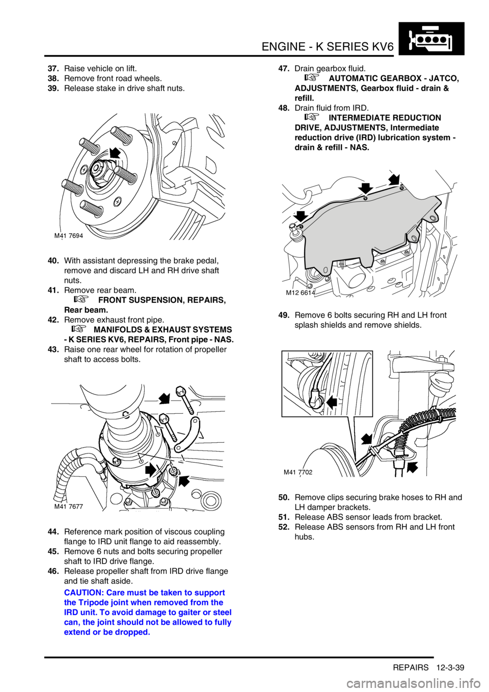
38.Remove front road wheels.
39.Release stake in drive shaft nuts.
40.With assistant depressing the brake pedal,
remove and discard LH and RH drive shaft
nuts.
41.Remove rear beam.
+ FRONT SUSPENSION, REPAIRS,
Rear beam.
42.Remove exhaust front pipe.
+ MANIFOLDS & EXHAUST SYSTEMS
- K SERIES KV6, REPAIRS, Front pipe - NAS.
43.Raise one rear wheel for rotation of propeller
shaft to access bolts.
44.Reference mark position of viscous coupling
flange to IRD unit flange to aid reassembly.
45.Remove 6 nuts and bolts securing propeller
shaft to IRD drive flange.
46.Release propeller shaft from IRD drive flange
and tie shaft aside.
CAUTION: Care must be taken to support
the Tripode joint when removed from the
IRD unit. To avoid damage to gaiter or steel
can, the joint should not be allowed to fully
extend or be dropped.47.Drain gearbox fluid.
+ AUTOMATIC GEARBOX - JATCO,
ADJUSTMENTS, Gearbox fluid - drain &
refill.
48.Drain fluid from IRD.
+ INTERMEDIATE REDUCTION
DRIVE, ADJUSTMENTS, Intermediate
reduction drive (IRD) lubrication system -
drain & refill - NAS.
49.Remove 6 bolts securing RH and LH front
splash shields and remove shields.
50.Remove clips securing brake hoses to RH and
LH damper brackets.
51.Release ABS sensor leads from bracket.
52.Release ABS sensors from RH and LH front
hubs.
M12 6614