sensor LAND ROVER FREELANDER 2001 Manual Online
[x] Cancel search | Manufacturer: LAND ROVER, Model Year: 2001, Model line: FREELANDER, Model: LAND ROVER FREELANDER 2001Pages: 1007, PDF Size: 23.47 MB
Page 455 of 1007

AUTOMATIC GEARBOX - JATCO
44-20 REPAIRS
25.Remove nut and bolt, adjacent to CKP sensor,
securing gearbox to engine.
26.Release throttle cable from abutment bracket
and disconnect cable from throttle body cam, if
fitted.
27.Depress collars and release 2 breather pipes
from throttle housing, if fitted.
28. Vehicles with cruise control: Disconnect
vacuum hose from cruise control actuator.29.Remove 4 Torx screws securing throttle
housing, release throttle housing and position
aside.
Non NAS throttle housing shown.
30.Remove and discard 'O' ring from throttle
housing.
31.Remove starter motor.
+ CHARGING AND STARTING,
REPAIRS, Starter motor - KV6.
M19 3198
Page 457 of 1007

AUTOMATIC GEARBOX - JATCO
44-22 REPAIRS
42.Remove 2 top bolts securing gearbox to
engine.
43.Release gearbox from 2 dowels.
44.Manoeuvre and lower gearbox to floor.
45.Fit converter retaining plate and secure with
bolts.Refit
1.Remove torque converter retaining plate.
2.Ensure converter is fully located in oil pump
drive by checking depth 'A' as illustrated. Depth
A = 4 mm.
3.Clean gearbox to engine mating faces, dowels
and dowel holes.
4.Fit gearbox assembly.
5.Fit bolts securing gearbox and tighten to 85 Nm
(63 lbf.ft).
6.Position LH mounting bracket to gearbox, fit
and tighten bolts to 85 Nm (63 lbf.ft).
7.Position LH mounting to body, fit and tighten
bolts to 48 Nm (35 lbf.ft).
8.Align gearbox bracket to LH body mounting, fit
and tighten through bolt to 100 Nm (74 lbf.ft).
9.Disconnect lifting equipment.
10.Remove nuts and bolts securing lifting brackets
to gearbox and remove brackets.
11.Connect engine and gearbox harness
multiplugs to main harness.
12.Secure multiplugs to clips.
13.Position engine earth lead and secure with bolt.
14.Fit starter motor.
+ CHARGING AND STARTING,
REPAIRS, Starter motor - KV6.
15.Clean throttle housing and manifold chamber
mating faces.
16.Fit new seal to inlet manifold chamber.
17.Position throttle housing to manifold chamber,
fit Torx screws and tighten to 7 Nm (7 lbf.ft).
18.Connect throttle inner cable to throttle cam and
secure outer cable in abutment bracket, if fitted.
19.Connect hose to cruise control actuator.
20.Secure breather hoses to throttle housing, if
fitted.
21.Adjust throttle cable, if fitted.
+ FUEL DELIVERY SYSTEM -
PETROL, ADJUSTMENTS, Throttle cable -
check and adjust - KV6.
22.Clean CKP sensor and mating face.
M44 1689
A
M44 1668
Page 458 of 1007

AUTOMATIC GEARBOX - JATCO
REPAIRS 44-23
23.Fit CKP sensor, fit bolt and tighten to 9 Nm (7
lbf.ft).
24.Position fluid cooler, tighten M12 bolts to 85 Nm
(63 lbf.ft) and M8 bolt to 25 Nm (18 lbf.ft).
25.Clean fluid cooler unions.
26.Lubricate new 'O' rings with clean transmission
fluid and fit 'O' rings to fluid cooler hoses.
+ CAPACITIES, FLUIDS,
LUBRICANTS AND SEALANTS,
Lubrication.
27.Connect fluid cooler hoses to gearbox and
tighten unions to 18 Nm (13 lbf.ft).
28.Clean exhaust manifold and mating face on
cylinder head.
29.Fit exhaust manifold gasket.
30.Position exhaust manifold, fit nuts and
progressively tighten, from centre outwards to
45 Nm (33 lbf.ft).
31.Connect HO2S multiplug and secure to support
bracket.
32.Position IRD cooling hose retainer, fit bolt and
tighten to 25 Nm (18 lbf.ft).
33.Align marks on drive plate to torque converter.
34.Fit bolts securing drive plate to torque converter
and tighten bolts to 45 Nm (33 lbf.ft).
35.Clean torque converter access plate.
36.Position access plate, fit bolts and tighten to 9
Nm (7 lbf.ft).
37.Clean end of drive shaft and mating splines in
gearbox.
38.Fit new circlip to LH drive shaft.
39.With assistance pull hub outwards, align drive
shaft and fit to gearbox, taking care not to
damage drive shaft oil seal.
CAUTION: Pull the drive shaft to ensure the
circlip is fully engaged and retains the shaft.
40.Fit splash shield and secure with bolts.
41.Position trunnion to selector lever, locate inner
cable through trunnion, do not tighten nut at this
stage.
42.Position selector cable to gearbox bracket and
secure with clip.
43.Adjust selector cable.
+ AUTOMATIC GEARBOX - JATCO,
ADJUSTMENTS, Selector cable - adjust.
44.Fit IRD.
+ INTERMEDIATE REDUCTION
DRIVE, REPAIRS, Intermediate reduction
drive (IRD) unit - KV6.
45.Connect battery earth lead.
46.Fit engine acoustic cover.
+ ENGINE - K SERIES KV6, REPAIRS,
Cover - engine acoustic.
47.Untie and close bonnet.
Gearbox - Td4
$% 44.20.02.99
Remove
1.Disconnect battery earth lead.
2.Tie bonnet back in upright position.
3.Remove intake ducting assembly.
+ FUEL DELIVERY SYSTEM - DIESEL,
REPAIRS, Ducting - intake assembly.
4.Remove fluid cooler.
+ AUTOMATIC GEARBOX - JATCO,
REPAIRS, Fluid cooler - Td4.
5.Remove starter motor.
+ CHARGING AND STARTING,
REPAIRS, Starter motor - Td4.
6.Remove IRD.
+ INTERMEDIATE REDUCTION
DRIVE, REPAIRS, Intermediate reduction
drive (IRD) unit - Td4.
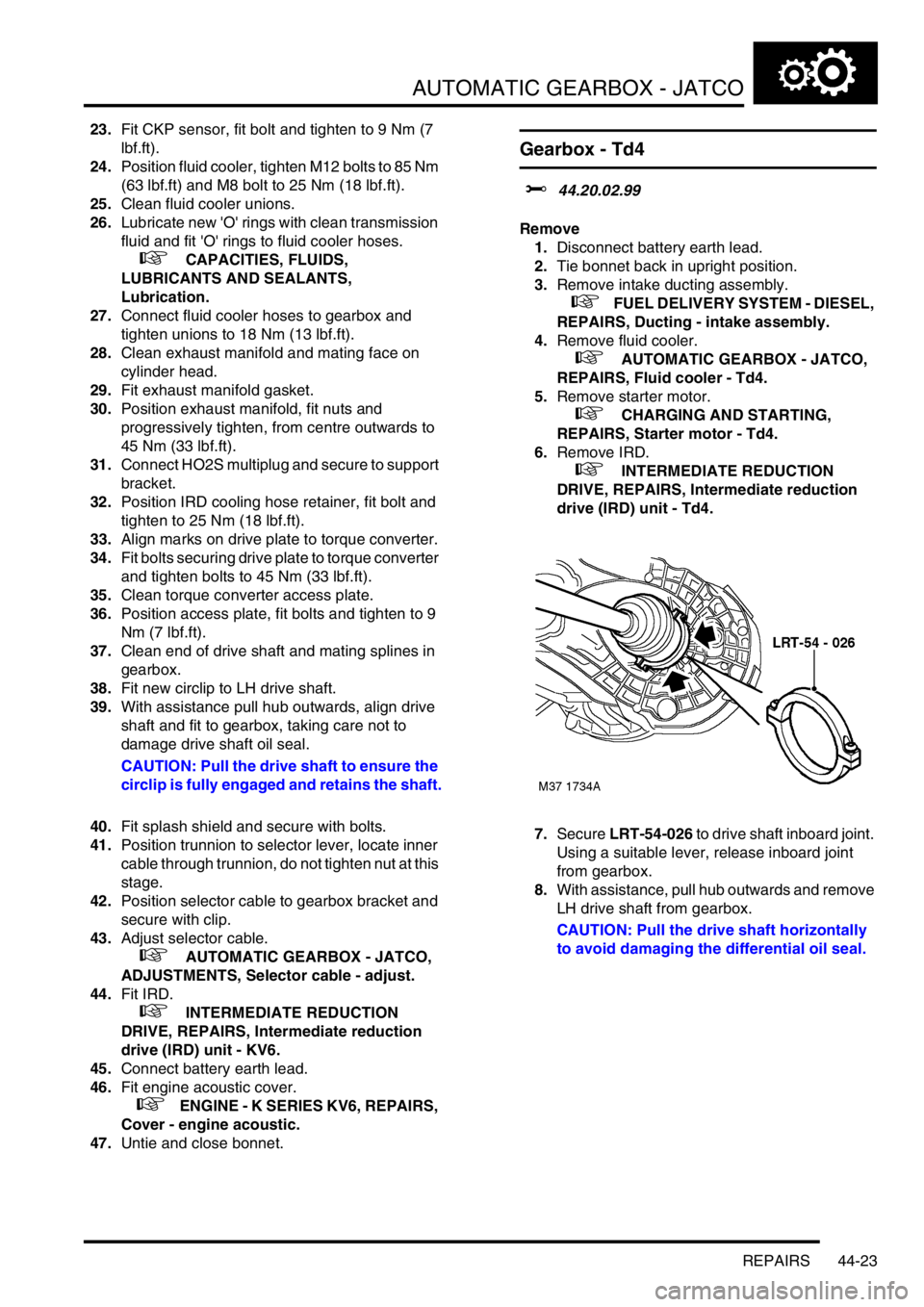
7.Secure LRT-54-026 to drive shaft inboard joint.
Using a suitable lever, release inboard joint
from gearbox.
8.With assistance, pull hub outwards and remove
LH drive shaft from gearbox.
CAUTION: Pull the drive shaft horizontally
to avoid damaging the differential oil seal.
Page 468 of 1007

DRIVESHAFTS
REPAIRS 47-1
DRIV ESHAFTS REPAIRS
Shaft with both joints - LH
$% 47.10.01
Remove
1.Disconnect battery earth lead.
2.Raise front of vehicle.
WARNING: Do not work on or under a
vehicle supported only by a jack. Always
support the vehicle on safety stands.
3.Remove road wheel.
4.Remove underbelly panel.
+ EXTERIOR FITTINGS, REPAIRS,
Panel - underbelly.
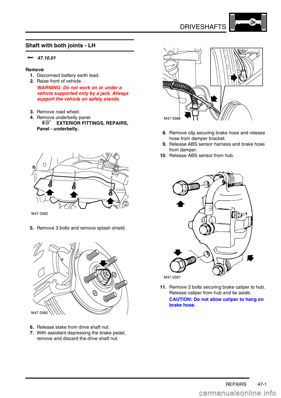
5.Remove 3 bolts and remove splash shield.
6.Release stake from drive shaft nut.
7.With assistant depressing the brake pedal,
remove and discard the drive shaft nut.8.Remove clip securing brake hose and release
hose from damper bracket.
9.Release ABS sensor harness and brake hose
from damper.
10.Release ABS sensor from hub.
11.Remove 2 bolts securing brake caliper to hub.
Release caliper from hub and tie aside.
CAUTION: Do not allow caliper to hang on
brake hose.
Page 469 of 1007

DRIVESHAFTS
47-2 REPAIRS
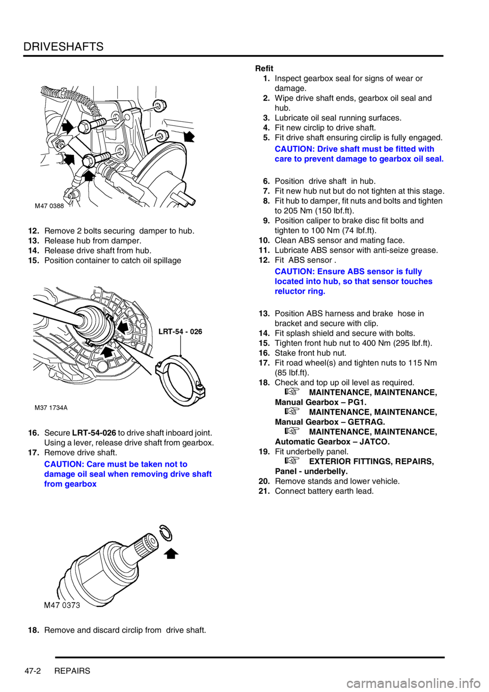
12.Remove 2 bolts securing damper to hub.
13.Release hub from damper.
14.Release drive shaft from hub.
15.Position container to catch oil spillage
16.Secure LRT-54-026 to drive shaft inboard joint.
Using a lever, release drive shaft from gearbox.
17.Remove drive shaft.
CAUTION: Care must be taken not to
damage oil seal when removing drive shaft
from gearbox
18.Remove and discard circlip from drive shaft.Refit
1.Inspect gearbox seal for signs of wear or
damage.
2.Wipe drive shaft ends, gearbox oil seal and
hub.
3.Lubricate oil seal running surfaces.
4.Fit new circlip to drive shaft.
5.Fit drive shaft ensuring circlip is fully engaged.
CAUTION: Drive shaft must be fitted with
care to prevent damage to gearbox oil seal.
6.Position drive shaft in hub.
7.Fit new hub nut but do not tighten at this stage.
8.Fit hub to damper, fit nuts and bolts and tighten
to 205 Nm (150 lbf.ft).
9.Position caliper to brake disc fit bolts and
tighten to 100 Nm (74 lbf.ft).
10.Clean ABS sensor and mating face.
11.Lubricate ABS sensor with anti-seize grease.
12.Fit ABS sensor .
CAUTION: Ensure ABS sensor is fully
located into hub, so that sensor touches
reluctor ring.
13.Position ABS harness and brake hose in
bracket and secure with clip.
14.Fit splash shield and secure with bolts.
15.Tighten front hub nut to 400 Nm (295 lbf.ft).
16.Stake front hub nut.
17.Fit road wheel(s) and tighten nuts to 115 Nm
(85 lbf.ft).
18.Check and top up oil level as required.
+ MAINTENANCE, MAINTENANCE,
Manual Gearbox – PG1.
+ MAINTENANCE, MAINTENANCE,
Manual Gearbox – GETRAG.
+ MAINTENANCE, MAINTENANCE,
Automatic Gearbox – JATCO.
19.Fit underbelly panel.
+ EXTERIOR FITTINGS, REPAIRS,
Panel - underbelly.
20.Remove stands and lower vehicle.
21.Connect battery earth lead.
Page 470 of 1007

DRIVESHAFTS
REPAIRS 47-3
Shaft with both joints - RH
$% 47.10.02
Remove
1.Disconnect battery earth lead.
2.Raise front of vehicle.
WARNING: Do not work on or under a
vehicle supported only by a jack. Always
support the vehicle on safety stands.
3.Remove road wheel.
4.Remove underbelly panel.
+ EXTERIOR FITTINGS, REPAIRS,
Panel - underbelly.
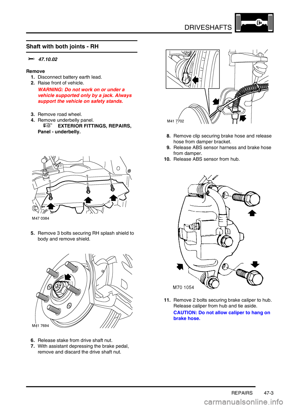
5.Remove 3 bolts securing RH splash shield to
body and remove shield.
6.Release stake from drive shaft nut.
7.With assistant depressing the brake pedal,
remove and discard the drive shaft nut.8.Remove clip securing brake hose and release
hose from damper bracket.
9.Release ABS sensor harness and brake hose
from damper.
10.Release ABS sensor from hub.
11.Remove 2 bolts securing brake caliper to hub.
Release caliper from hub and tie aside.
CAUTION: Do not allow caliper to hang on
brake hose.
Page 471 of 1007

DRIVESHAFTS
47-4 REPAIRS
12.Remove 2 bolts securing damper to hub.
13.Release hub from damper.
14.Release drive shaft from hub.
15.Position container to catch oil spillage.
16.Secure LRT-54-026 to drive shaft inboard joint.
Using a lever, release drive shaft from gearbox.
17.Remove drive shaft.
CAUTION: Care must be taken not to
damage oil seal when removing drive shaft
from gearbox18.Remove and discard circlip from drive shaft.
Refit
1.Inspect gearbox seal for signs of wear or
damage.
2.Wipe drive shaft ends, gearbox oil seal and
hub.
3.Lubricate oil seal running surfaces.
4.Fit new circlip to drive shaft.
5.Fit drive shaft ensuring circlip is fully engaged.
CAUTION: Drive shaft must be fitted with
care to prevent damage to gearbox oil seal.
6.Position drive shaft in hub.
7.Fit new hub nut but do not tighten at this stage.
8.Fit hub to damper, fit nuts and bolts and tighten
to 205 Nm (150 lbf.ft).
9.Position caliper to brake disc fit bolts and
tighten to 100 Nm (74 lbf.ft).
10.Clean ABS sensor and mating face.
11.Lubricate ABS sensor with anti-seize grease.
12.Fit ABS sensor .
CAUTION: Ensure ABS sensor is fully
located into hub, so that sensor touches
reluctor ring.
13.Position ABS harness and brake hose in
bracket and secure with clip.
14.Fit splash shield and secure with bolts.
15.Tighten front hub nut to 400 Nm (295 lbf.ft).
16.Stake front hub nut.
17.Fit road wheel(s) and tighten nuts to 115 Nm
(85 lbf.ft).
18.Check and top up oil level as required.
+ MAINTENANCE, MAINTENANCE,
Intermediate Reduction Drive - Non NAS
models.
19.Fit underbelly panel.
+ EXTERIOR FITTINGS, REPAIRS,
Panel - underbelly.
20.Remove stands and lower vehicle.
21.Connect battery earth lead.
Page 522 of 1007

FRONT SUSPENSION
REPAIRS 60-3
Bearing - hub
$% 60.25.14
Remove
1.Raise front of vehicle.
WARNING: Do not work on or under a
vehicle supported only by a jack. Always
support the vehicle on safety stands.
2.Remove road wheel.
3.Release stake in drive shaft nut.
4.With an assistant applying brakes, remove and
discard drive shaft hub nut.
5.Remove clip securing RH brake hose to
support bracket, release hose from bracket.
Release ABS sensor and pad wear sensor
harnesses from bracket.6.Remove 2 bolts securing brake caliper to hub.
Release caliper from hub and tie aside.
CAUTION: Do not allow caliper to hang on
brake hose.
7.Mark brake disc to hub relationship.
8.Remove 2 screws securing brake disc and
remove brake disc.
Page 525 of 1007

FRONT SUSPENSION
60-6 REPAIRS
Refit
1.Clean hub and drive flange.
2.Support hub on tool LRT-54-016 and press in
new bearing using LRT-54-015.
CAUTION: One side of the bearing is
magnetic. The magnetic side is identifiable
by the application of a matt black finish. The
magnetic side must face towards the
inboard side of the vehicle. Before fitting
the bearing, ensure the magnetic face is
clean. The bearing must be handled with
extreme care.
3.Fit circlip to hub.
4.Fit brake disc shield, fit bolts and tighten to 8.5
Nm (6.5 lbf.ft).
5.Support bearing on tool LRT-54-015 and press
drive flange into bearing using LRT-54-014.
6.Clean drive shaft.7.Fit hub assembly to lower joint, fit new nut and
tighten to 65 Nm (48 lbf.ft).
8.Fit drive shaft to hub.
9.Fit hub to damper, fit nuts and bolts and tighten
to 205 Nm (151 lbf.ft).
10.Clean brake disc to drive flange mating faces.
11.Fit disc to drive flange, align reference marks, fit
screws and tighten to 5 Nm (4 lbf.ft).
12.Clean mating faces of caliper and hub.
13.Position caliper to brake disc fit bolts and
tighten to 100 Nm (74 lbf.ft).
14.Fit brake hose to abutment bracket and fit clip.
15.Clean ABS sensor, smear sensor with an anti-
seize grease and fit sensor to hub.
CAUTION: Ensure ABS sensor is fully
located into hub, so that sensor touches
pole wheel teeth.
16.Fit ABS sensor lead to bracket.
17.Fit new drive shaft nut and tighten to 400 Nm
(295 lbf.ft). Stake nut to shaft.
18.Stake drive shaft hub nut.
19.Fit road wheel(s) and tighten nuts to 115 Nm
(85 lbf.ft).
20.Remove stands and lower vehicle.
Page 526 of 1007

FRONT SUSPENSION
REPAIRS 60-7
Damper
$% 60.30.02
Remove
1.Disconnect battery earth lead.
2.Raise front of vehicle.
WARNING: Do not work on or under a
vehicle supported only by a jack. Always
support the vehicle on safety stands.
3.Remove road wheel.
4.Remove clip securing brake hose to bracket on
damper.
5.Release ABS sensor harness and brake hose
from damper.
6.Release ABS sensor from hub.7.Remove 2 bolts securing brake caliper to hub.
Release caliper from hub and tie aside.
CAUTION: Do not allow caliper to hang on
brake hose.
8.Remove nut securing track rod to steering arm
and break taper joint using LRT-57-043.