dimensions LAND ROVER FREELANDER 2001 Workshop Manual
[x] Cancel search | Manufacturer: LAND ROVER, Model Year: 2001, Model line: FREELANDER, Model: LAND ROVER FREELANDER 2001Pages: 1007, PDF Size: 23.47 MB
Page 5 of 1007
CONTENTS
2CONTENTS
GENERAL DATA ..................................................................................... 04-1
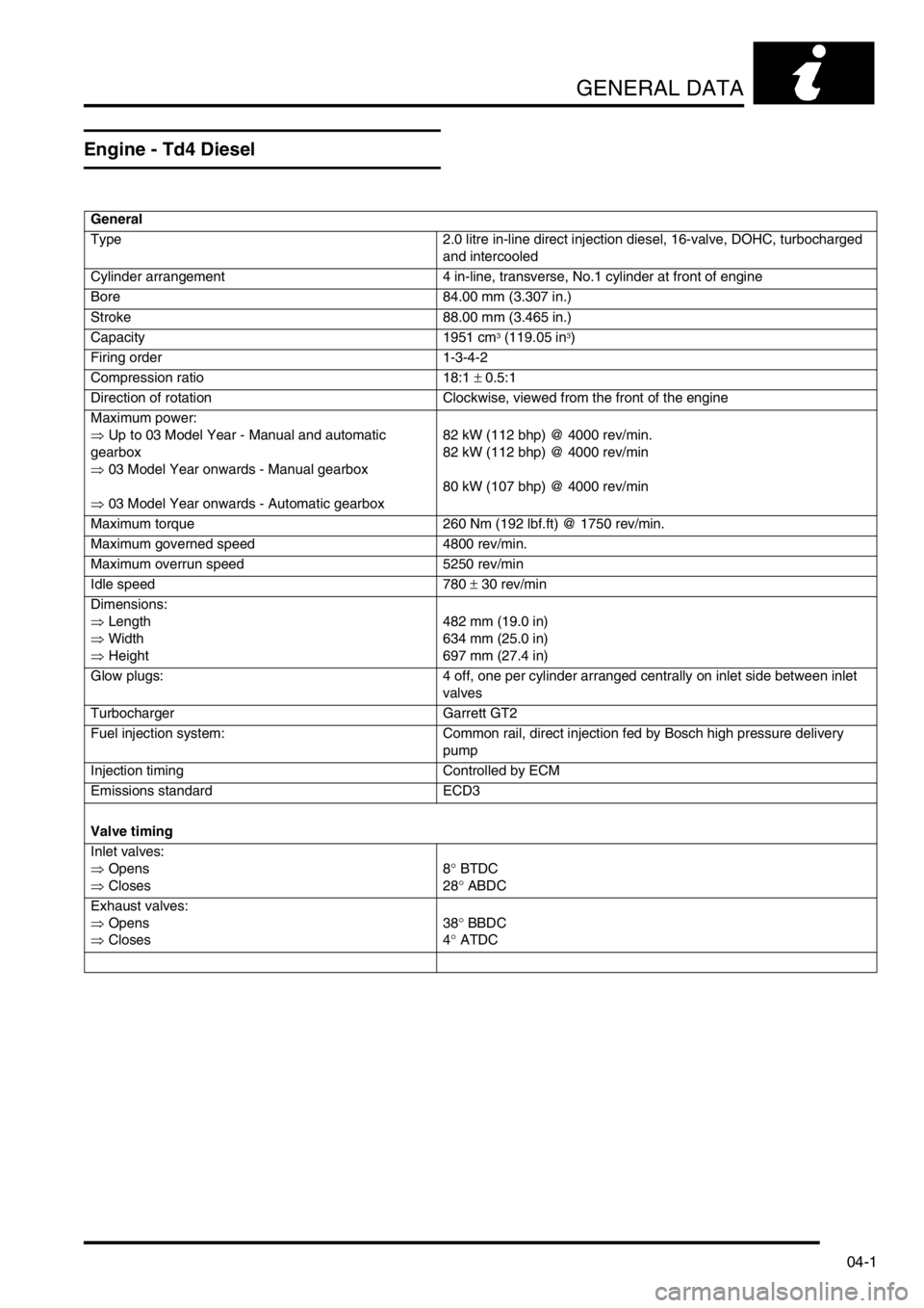
Engine - Td4 Diesel ........................................................................................................................ 04-1
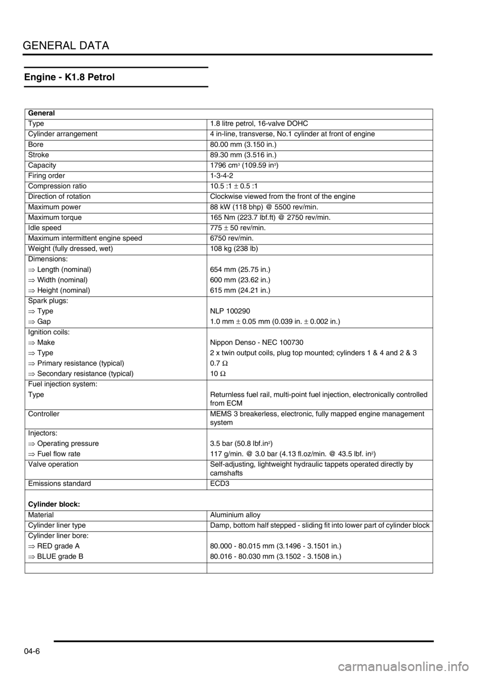
Engine - K1.8 Petrol........................................................................................................................ 04-6
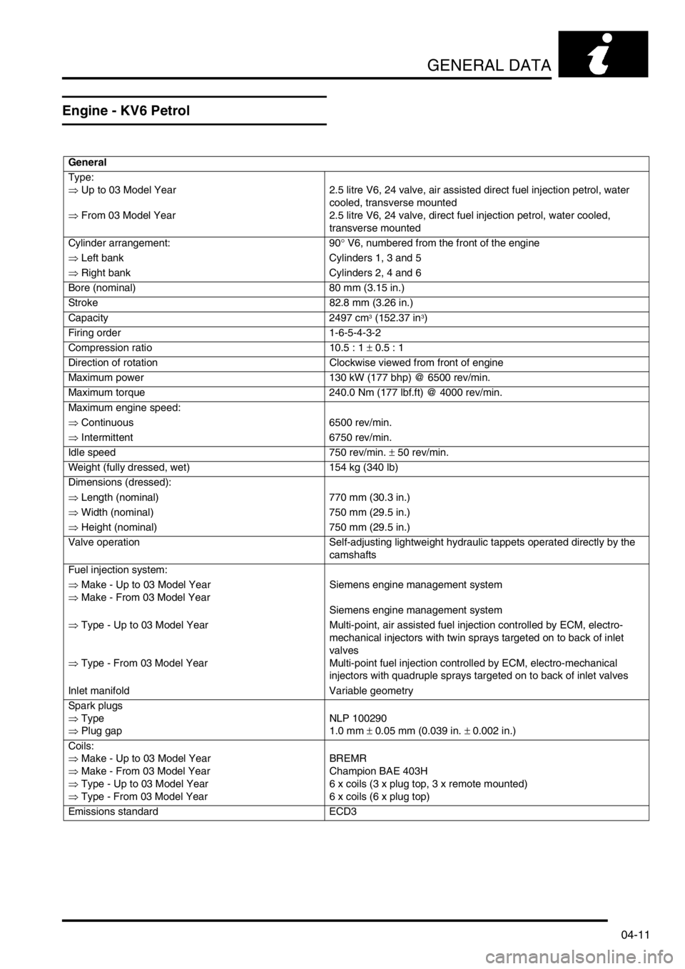
Engine - KV6 Petrol ........................................................................................................................ 04-11
Fuel system - Td4 Diesel ................................................................................................................ 04-16
Fuel system - K1.8 Petrol ............................................................................................................... 04-18
Fuel system - KV6 Petrol ................................................................................................................ 04-18
Cooling system - Td4 Diesel ........................................................................................................... 04-19
Cooling system - K1.8 Petrol .......................................................................................................... 04-19
Cooling system - KV6 Petrol ........................................................................................................... 04-19
Clutch.............................................................................................................................................. 04-20
Manual Gearbox - Getrag ............................................................................................................... 04-21
Manual Gearbox - PG1 ................................................................................................................... 04-22
Intermediate Reduction Drive (IRD)................................................................................................ 04-24
Automatic Gearbox - Jatco ............................................................................................................. 04-25
Rear Axle and Final Drive ............................................................................................................... 04-26
Steering .......................................................................................................................................... 04-27
Front Suspension............................................................................................................................ 04-28
Rear Suspension ............................................................................................................................ 04-30
Brakes............................................................................................................................................. 04-31
Wheels and tyres ............................................................................................................................ 04-32
Tyre pressures ................................................................................................................................ 04-32
Heating and Ventilation................................................................................................................... 04-33
Air Conditioning .............................................................................................................................. 04-33
Electrical - Td4 engine .................................................................................................................... 04-34
Electrical - K1.8 engine ................................................................................................................... 04-34
Electrical - KV6 engine ................................................................................................................... 04-34
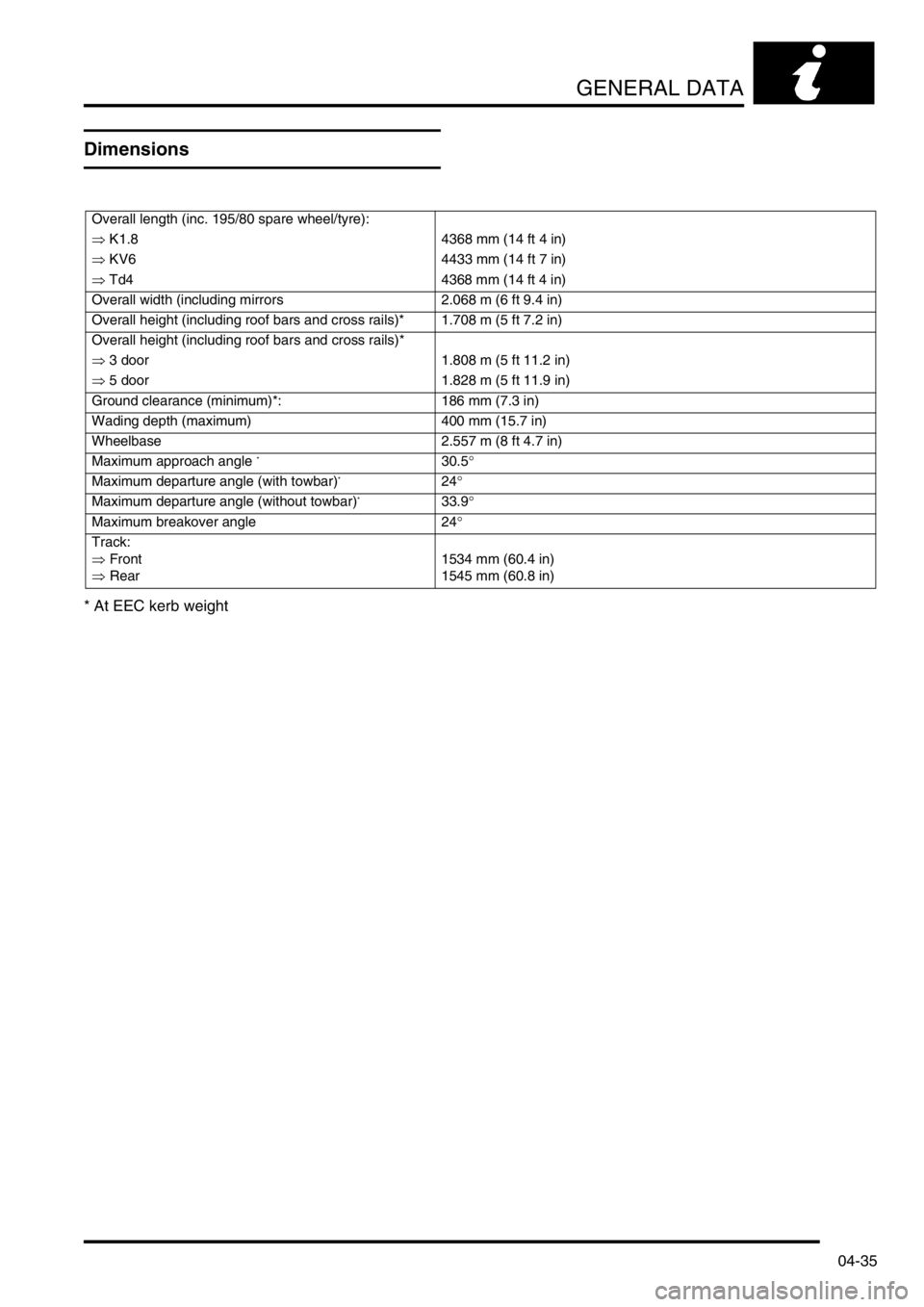
Dimensions ..................................................................................................................................... 04-35
Weights ........................................................................................................................................... 04-36
IDENTIFICATION NUMBERS .................................................................. 05-1
Vehicle Identification Number ......................................................................................................... 05-1
Identification Number Locations ..................................................................................................... 05-2
Page 18 of 1007
CONTENTS
CONTENTS 15
SUNROOF................................................................................................. 76-6-1
REPAIRS
Sun/sliding roof - complete - front - 3 door ..................................................................................... 76-6-1
Wind deflector - sun/sliding roof - 3 door ....................................................................................... 76-6-2
Seal - tray - sun /sliding roof - front ................................................................................................ 76-6-3
Sun/sliding roof - complete - front - 5 door ..................................................................................... 76-6-4
Glass panel - sun/sliding roof - front - 5 door ................................................................................. 76-6-4
Seal - panel glass - sun roof - 5 door .............................................................................................. 76-6-5
Motor - sun/sliding roof - front - 5 door ........................................................................................... 76-6-5
Drive cables & slide assemblies - sun/sliding roof - front - 5 door ................................................. 76-6-7
Drain tube - sun/sliding roof - front - each - 5 door ........................................................................ 76-6-8
Drain tube - sun/sliding roof - rear - each - 5 door ......................................................................... 76-6-9
Finisher - flange to headlining - front ............................................................................................. 76-6-9
Wind deflector - sun/sliding roof - 5 door ........................................................................................ 76-6-10
Sun blind - front - one - 5 door ....................................................................................................... 76-6-10
Switch - sun/sliding roof - front ....................................................................................................... 76-6-11
Seal - tray - sun /sliding roof - front - 5 door ................................................................................... 76-6-11
HOOD ........................................................................................................ 76-7-1
REPAIRS
Hard top - remove for access & refit ............................................................................................... 76-7-1
Frame & hood cover - assembly - remove for access & refit ......................................................... 76-7-2
Hood outer cover ............................................................................................................................ 76-7-4
Glass - body side - hard back ......................................................................................................... 76-7-5
Seal - hard back - primary............................................................................................................... 76-7-7
Catch and retainer - hard-back - front ............................................................................................. 76-7-8
Catch and retainer - hard-back - rear .............................................................................................. 76-7-9
BODY DIMENSIONS ................................................................................ 77-1-1
BODY DIMENSIONS
Dimensional Information ................................................................................................................. 77-1-1
Dimensional Illustrations ................................................................................................................. 77-1-3
BODY GAPS AND PROFILES
Gap and Profile Measurements ...................................................................................................... 77-1-17
Page 26 of 1007
INTRODUCTION
01-1
INTRODUCTION
How To Use This Manual
General
To assist in the use of this Manual, it is divided into
sections and sub-sections. The section title is given
at the top of each page and the relevant sub-section
is given at the bottom.
There is a single contents section at the front of the
Manual, which is divided by section and sub-section.
Each section is numbered from page 1.
The individual items comprising repair operations are
to be followed in the sequence in which they appear.
Item numbers shown in illustrations are referred to in
the associated text.
Adjustment, Repair and Overhaul operations include
reference to Service tool numbers and the
associated illustration depicts the tool in use.
Adjustment and repair operations also include
reference to wear limits, relevant data, torque
figures, specialist information and useful assembly
details. Each adjustment or repair operation is given
a Service Repair Operation (SRO) number.
WARNINGS, CAUTIONS and NOTES have the
following meanings:
WARNING: Procedures which must be followed
precisely to avoid the possibility of injury.
CAUTION: Calls attention to procedures which
must be followed to avoid damage to
components.
NOTE: Gives helpful information.
References
References to the LH or RH side given in this Manual
are made when viewing the vehicle from the rear.
With the engine and gearbox assembly removed, the
crankshaft pulley end of the engine is referred to as
the front.
Operations covered in this Manual do not include
reference to testing the vehicle after repair. It is
essential that work is inspected and tested after
completion and if necessary a road test of the vehicle
is carried out. This is of particular importance where
safety related items are concerned.
Dimensions
The dimensions quoted are to design engineering
specification. Service limits are included where
applicable.Electrical Reference Library (ERL) and Circuit
Diagrams
The Electrical Reference Library (ERL) and Circuit
Diagrams are separate publications intended for use
by trained Land Rover technicians and should be
referred to when attempting to diagnose electrically
related concerns.
The ERL contains descriptions of how the circuits
operate, fuse details, earth point locations, and a
definitive guide to the attributes and location of every
connector on the vehicle.
The ERL is used in conjunction with the Circuit
Diagrams. Both publications are designed to support
all aspects of electrical fault diagnosis.
TESTBOOK (Fault Diagnostic Equipment)
Freelander is equipped with a number of electronic
control systems to provide optimum performance of
the vehicle's systems.
Diagnostic equipment (TESTBOOK/T4) is available
to assist with the fault diagnostic abilities of the
dealer workshop. In particular, the equipment can be
used to interrogate the Engine Control Module
(ECM) for diagnosis of emissions related faults which
may become evident by the illumination of the
Malfunction Indicator Lamp (MIL) in the instrument
pack. This feature is included in compliance with the
latest emissions legislation pertinent to a particular
market (e.g. EU3 for Europe, OBDII for North
America etc.).
This repair manual is produced as a reference
source to supplement Testbook/T4. When available,
the equipment should be used as the primary means
of fault diagnosis on electronically controlled
systems.
Features of TestbookT4 include:
lFully upgradable support for the technician
lStructured diagnostics to accommodate all skill
levels.
lTouch screen operation - Testbook only.
lDirect print out of screen information and test
results.
Page 38 of 1007
GENERAL INFORMATION
03-7
General fitting instructions
Precautions against damage
To avoid damage to the vehicle when carrying out
repairs, always adhere to the following:
lAlways fit wing and seat covers before
commencing work. Avoid spilling brake fluid or
battery acid on paintwork; immediately wash off
with water if this occurs.
lDisconnect the battery earth lead before starting
work, see ELECTRICAL PRECAUTIONS.
lAlways use the recommended service tool or a
satisfactory equivalent where specified.
lProtect exposed bearing surfaces, sealing
surfaces and screw threads from damage.
Component removal
Whenever possible, clean components and
surrounding area before removal.
lBlank off openings exposed by component
removal.
lImmediately seal fuel, oil or hydraulic lines when
apertures are exposed; use plastic caps or
plugs to prevent loss of fluid and ingress of dirt.
lClose open ends of oilways exposed by
component removal with tapered hardwood
plugs or conspicuous plastic plugs.
lImmediately a component is removed, place it in
a suitable container; use a separate container
for each component and its associated parts.
lClean bench and provide marking materials,
labels, containers and locking wire before
dismantling a component.
Dismantling
Observe scrupulous cleanliness when dismantling
components, particularly when brake, fuel or
hydraulic system parts are being worked on. A
particle of dirt or a cloth fragment could cause a
serious malfunction if trapped in these systems.Use the following procedures:
lBlow out all tapped holes, crevices, oilways and
fluid passages with an air line. Ensure that any
O-rings used for sealing are correctly replaced
or renewed if disturbed during the process.
lUse marking ink to identify mating parts and
ensure correct reassembly. Do not use a centre
punch or scriber to mark parts, they could
initiate cracks or distortion in marked
components.
lWire together mating parts where necessary to
prevent accidental interchange (e.g. roller
bearing components).
lWire labels on to all parts which are to be
renewed, and to parts requiring further
inspection before being passed for reassembly;
place these parts in separate containers from
those containing parts for rebuild.
lDo not discard a part due for renewal until after
comparing it with a new part to ensure that its
correct replacement has been obtained.
Cleaning components
Always use the recommended cleaning agent or
equivalent. Ensure that adequate ventilation is
provided when volatile degreasing agents are being
used. Do not use degreasing equipment for
components containing items which could be
damaged by the use of this process.
When washing under bonnet, never direct water onto
ECM, as water ingress may occur resulting in
damage to electrical components inside.
General Inspection
All components should be inspected for wear or
damage before being reassembled.
lNever inspect a component for wear or
dimensional check unless it is absolutely clean;
a slight smear of grease can conceal an
incipient failure.
lWhen a component is to be checked
dimensionally against recommended values,
use the appropriate measuring equipment
(surface plates, micrometers, dial gauges etc.).
Ensure the measuring equipment is calibrated
and in good serviceable condition.
lReject a component if its dimensions are
outside the specified tolerances, or if it appears
to be damaged.
lA part may be refitted if its critical dimension is
exactly to its tolerance limit and it appears to be
in satisfactory condition.
lUse 'Plastigauge' 12 Type PG-1 for checking
bearing surface clearances.
Page 64 of 1007
GENERAL DATA
04-1
GENERAL DATA
Engine - Td4 Diesel
General
Type 2.0 litre in-line direct injection diesel, 16-valve, DOHC, turbocharged
and intercooled
Cylinder arrangement 4 in-line, transverse, No.1 cylinder at front of engine
Bore 84.00 mm (3.307 in.)
Stroke 88.00 mm (3.465 in.)
Capacity 1951 cm
3 (119.05 in3)
Firing order 1-3-4-2
Compression ratio 18:1 ± 0.5:1
Direction of rotation Clockwise, viewed from the front of the engine
Maximum power:
⇒ Up to 03 Model Year - Manual and automatic
gearbox
⇒ 03 Model Year onwards - Manual gearbox
⇒ 03 Model Year onwards - Automatic gearbox82 kW (112 bhp) @ 4000 rev/min.
82 kW (112 bhp) @ 4000 rev/min
80 kW (107 bhp) @ 4000 rev/min
Maximum torque 260 Nm (192 lbf.ft) @ 1750 rev/min.
Maximum governed speed 4800 rev/min.
Maximum overrun speed 5250 rev/min
Idle speed 780 ± 30 rev/min
Dimensions:
⇒ Length
⇒ Width
⇒ Height482 mm (19.0 in)
634 mm (25.0 in)
697 mm (27.4 in)
Glow plugs: 4 off, one per cylinder arranged centrally on inlet side between inlet
valves
Turbocharger Garrett GT2
Fuel injection system: Common rail, direct injection fed by Bosch high pressure delivery
pump
Injection timing Controlled by ECM
Emissions standard ECD3
Valve timing
Inlet valves:
⇒ Opens
⇒ Closes8° BTDC
28° ABDC
Exhaust valves:
⇒ Opens
⇒ Closes38° BBDC
4° ATDC
Page 69 of 1007
GENERAL DATA
04-6
Engine - K1.8 Petrol
General
Type 1.8 litre petrol, 16-valve DOHC
Cylinder arrangement 4 in-line, transverse, No.1 cylinder at front of engine
Bore 80.00 mm (3.150 in.)
Stroke 89.30 mm (3.516 in.)
Capacity 1796 cm
3 (109.59 in3)
Firing order 1-3-4-2
Compression ratio 10.5 :1 ± 0.5 :1
Direction of rotation Clockwise viewed from the front of the engine
Maximum power 88 kW (118 bhp) @ 5500 rev/min.
Maximum torque 165 Nm (223.7 lbf.ft) @ 2750 rev/min.
Idle speed 775 ± 50 rev/min.
Maximum intermittent engine speed 6750 rev/min.
Weight (fully dressed, wet) 108 kg (238 lb)
Dimensions:
⇒ Length (nominal) 654 mm (25.75 in.)
⇒ Width (nominal) 600 mm (23.62 in.)
⇒ Height (nominal) 615 mm (24.21 in.)
Spark plugs:
⇒ Type NLP 100290
⇒ Gap 1.0 mm ± 0.05 mm (0.039 in. ± 0.002 in.)
Ignition coils:
⇒ Make Nippon Denso - NEC 100730
⇒ Type 2 x twin output coils, plug top mounted; cylinders 1 & 4 and 2 & 3
⇒ Primary resistance (typical) 0.7 Ω
⇒ Secondary resistance (typical) 10 Ω
Fuel injection system:
Type Returnless fuel rail, multi-point fuel injection, electronically controlled
from ECM
Controller MEMS 3 breakerless, electronic, fully mapped engine management
system
Injectors:
⇒ Operating pressure 3.5 bar (50.8 lbf.in
2)
⇒ Fuel flow rate 117 g/min. @ 3.0 bar (4.13 fl.oz/min. @ 43.5 lbf. in
2)
Valve operation Self-adjusting, lightweight hydraulic tappets operated directly by
camshafts
Emissions standard ECD3
Cylinder block:
Material Aluminium alloy
Cylinder liner type Damp, bottom half stepped - sliding fit into lower part of cylinder block
Cylinder liner bore:
⇒ RED grade A 80.000 - 80.015 mm (3.1496 - 3.1501 in.)
⇒ BLUE grade B 80.016 - 80.030 mm (3.1502 - 3.1508 in.)
Page 74 of 1007
GENERAL DATA
04-11
Engine - KV6 Petrol
General
Type:
⇒ Up to 03 Model Year
⇒ From 03 Model Year2.5 litre V6, 24 valve, air assisted direct fuel injection petrol, water
cooled, transverse mounted
2.5 litre V6, 24 valve, direct fuel injection petrol, water cooled,
transverse mounted
Cylinder arrangement: 90° V6, numbered from the front of the engine
⇒ Left bank Cylinders 1, 3 and 5
⇒ Right bank Cylinders 2, 4 and 6
Bore (nominal) 80 mm (3.15 in.)
Stroke 82.8 mm (3.26 in.)
Capacity 2497 cm
3 (152.37 in3)
Firing order 1-6-5-4-3-2
Compression ratio 10.5 : 1 ± 0.5 : 1
Direction of rotation Clockwise viewed from front of engine
Maximum power 130 kW (177 bhp) @ 6500 rev/min.
Maximum torque 240.0 Nm (177 lbf.ft) @ 4000 rev/min.
Maximum engine speed:
⇒ Continuous 6500 rev/min.
⇒ Intermittent 6750 rev/min.
Idle speed 750 rev/min. ± 50 rev/min.
Weight (fully dressed, wet) 154 kg (340 lb)
Dimensions (dressed):
⇒ Length (nominal) 770 mm (30.3 in.)
⇒ Width (nominal) 750 mm (29.5 in.)
⇒ Height (nominal) 750 mm (29.5 in.)
Valve operation Self-adjusting lightweight hydraulic tappets operated directly by the
camshafts
Fuel injection system:
⇒ Make - Up to 03 Model Year
⇒ Make - From 03 Model YearSiemens engine management system
Siemens engine management system
⇒ Type - Up to 03 Model Year
⇒ Type - From 03 Model YearMulti-point, air assisted fuel injection controlled by ECM, electro-
mechanical injectors with twin sprays targeted on to back of inlet
valves
Multi-point fuel injection controlled by ECM, electro-mechanical
injectors with quadruple sprays targeted on to back of inlet valves
Inlet manifold Variable geometry
Spark plugs
⇒ Type
⇒ Plug gapNLP 100290
1.0 mm ± 0.05 mm (0.039 in. ± 0.002 in.)
Coils:
⇒ Make - Up to 03 Model Year
⇒ Make - From 03 Model Year
⇒ Type - Up to 03 Model Year
⇒ Type - From 03 Model YearBREMR
Champion BAE 403H
6 x coils (3 x plug top, 3 x remote mounted)
6 x coils (6 x plug top)
Emissions standard ECD3
Page 98 of 1007
GENERAL DATA
04-35
Dimensions
* At EEC kerb weight
Overall length (inc. 195/80 spare wheel/tyre):
⇒ K1.8 4368 mm (14 ft 4 in)
⇒ KV6 4433 mm (14 ft 7 in)
⇒ Td4 4368 mm (14 ft 4 in)
Overall width (including mirrors 2.068 m (6 ft 9.4 in)
Overall height (including roof bars and cross rails)* 1.708 m (5 ft 7.2 in)
Overall height (including roof bars and cross rails)*
⇒ 3 door 1.808 m (5 ft 11.2 in)
⇒ 5 door 1.828 m (5 ft 11.9 in)
Ground clearance (minimum)*: 186 mm (7.3 in)
Wading depth (maximum) 400 mm (15.7 in)
Wheelbase 2.557 m (8 ft 4.7 in)
Maximum approach angle
*30.5°
Maximum departure angle (with towbar)
*24°
Maximum departure angle (without towbar)
*33.9°
Maximum breakover angle 24°
Track:
⇒ Front
⇒ Rear1534 mm (60.4 in)
1545 mm (60.8 in)
Page 736 of 1007
BODY DIMENSIONS
BODY DIMENSIONS 77-1-1
BODY DIMENSIONS BODY DIMENSIONS
Dimensional Information
Measurement Types
The following dimensional information is shown so as to assist the technician in the diagnosis and repair of body
panels. The information is shown in two different ways. There are X,Y,Z dimensions and actual point to point
dimensions.
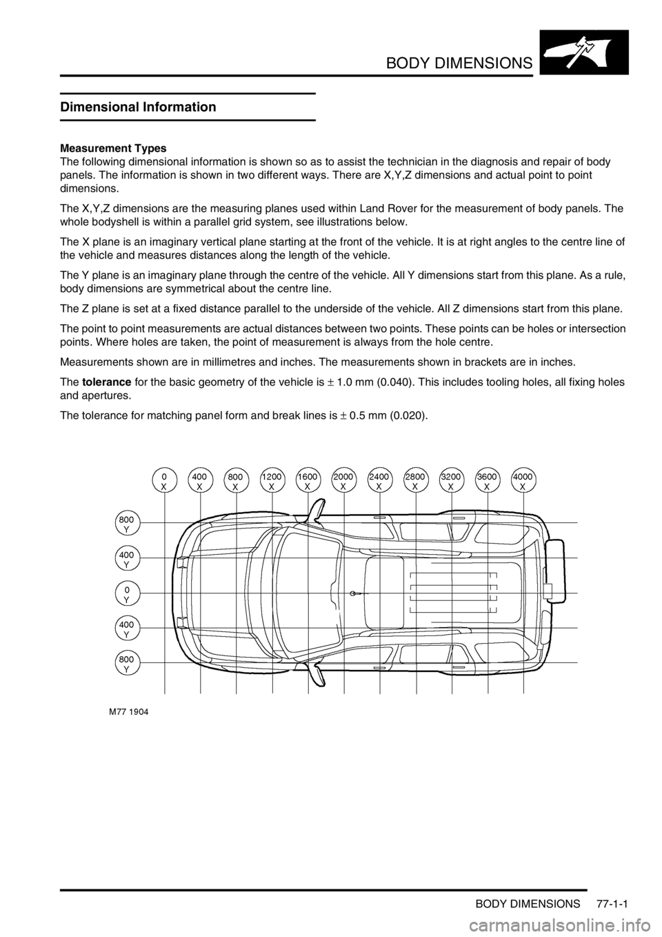
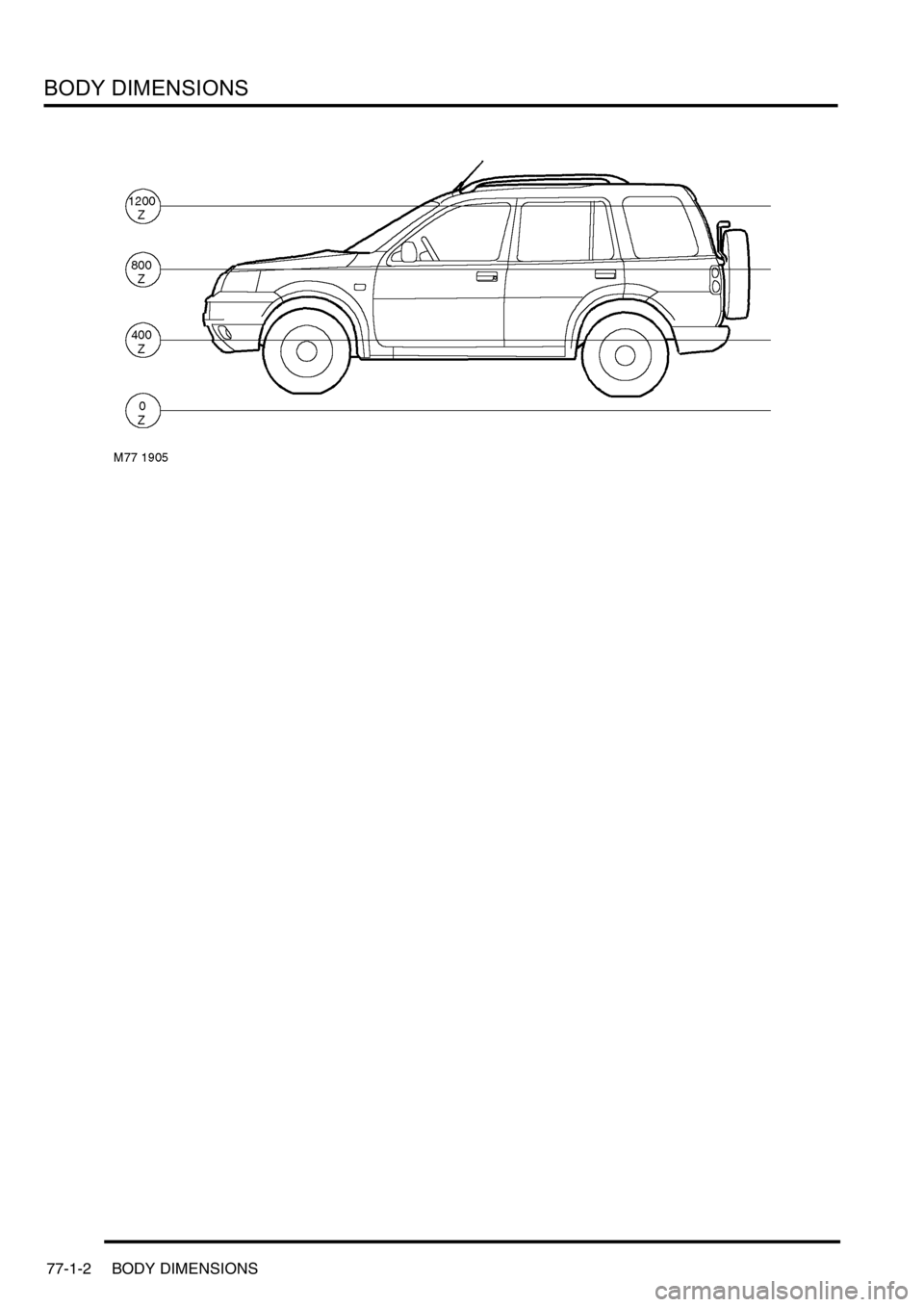
The X,Y,Z dimensions are the measuring planes used within Land Rover for the measurement of body panels. The
whole bodyshell is within a parallel grid system, see illustrations below.
The X plane is an imaginary vertical plane starting at the front of the vehicle. It is at right angles to the centre line of
the vehicle and measures distances along the length of the vehicle.
The Y plane is an imaginary plane through the centre of the vehicle. All Y dimensions start from this plane. As a rule,
body dimensions are symmetrical about the centre line.
The Z plane is set at a fixed distance parallel to the underside of the vehicle. All Z dimensions start from this plane.
The point to point measurements are actual distances between two points. These points can be holes or intersection
points. Where holes are taken, the point of measurement is always from the hole centre.
Measurements shown are in millimetres and inches. The measurements shown in brackets are in inches.
The tolerance for the basic geometry of the vehicle is ± 1.0 mm (0.040). This includes tooling holes, all fixing holes
and apertures.
The tolerance for matching panel form and break lines is ± 0.5 mm (0.020).
Page 737 of 1007
BODY DIMENSIONS
77-1-2 BODY DIMENSIONS