fuse box LAND ROVER FREELANDER 2001 Workshop Manual
[x] Cancel search | Manufacturer: LAND ROVER, Model Year: 2001, Model line: FREELANDER, Model: LAND ROVER FREELANDER 2001Pages: 1007, PDF Size: 23.47 MB
Page 24 of 1007

CONTENTS
CONTENTS 21
WINDOWS ................................................................................................ 86-5-1
REPAIRS
Motor & control unit - front door - 3 door ......................................................................................... 86-5-1
Motor & control unit - front door - 5 door ......................................................................................... 86-5-2
Switch - master window - 5 door - from 04MY ................................................................................ 86-5-2
Relay - control - tail door glass ....................................................................................................... 86-5-3
Microswitch - hardtop sensing - 3 door ........................................................................................... 86-5-4
Relay - heated front screen ........................................................................................................... 86-5-5
Switch - backlight heater ................................................................................................................. 86-5-6
IN CAR ENTERTAINMENT ...................................................................... 86-6-1
REPAIRS
Radio - up to 04MY ......................................................................................................................... 86-6-1
Radio/CD - from 04MY .................................................................................................................... 86-6-2
Speaker - rear - 3 door .................................................................................................................... 86-6-3
Speaker - rear - 5 door .................................................................................................................... 86-6-3
Speaker - front ................................................................................................................................ 86-6-4
Aerial - manual - 3 door .................................................................................................................. 86-6-4
Aerial - manual - 5 door .................................................................................................................. 86-6-5
Coaxial lead - front aerial - 3 door ................................................................................................... 86-6-6
Coaxial lead - front aerial - 5 door ................................................................................................... 86-6-7
Speaker - tweeter - front ................................................................................................................. 86-6-8
Speaker - tweeter - rear - 3 door ..................................................................................................... 86-6-9
Amplifier - power ............................................................................................................................ 86-6-10
Sub-woofer assembly .................................................................................................................... 86-6-11
Coaxial lead - extension.................................................................................................................. 86-6-12
HARNESSES ............................................................................................ 86-7-1
REPAIRS
Fuse box - passenger compartment ............................................................................................... 86-7-1
Harness - main ................................................................................................................................ 86-7-2
Harness - tailgate ............................................................................................................................ 86-7-12
Harness - interior lights - 5 door ...................................................................................................... 86-7-15
Harness - front door - 5 door ........................................................................................................... 86-7-15
Harness - rear door ......................................................................................................................... 86-7-16
DRIVER CONTROLS ................................................................................ 86-8-1
REPAIRS
Switch - remote control - audio system .......................................................................................... 86-8-1
Switch - park distance control (PDC) - from 04 MY ........................................................................ 86-8-1
Control unit (ECU) - parking aid - from 04MY ................................................................................. 86-8-2
Sensor - parking aid - rear - from 04MY ......................................................................................... 86-8-2
Sounder - parking aid - rear - from 04MY ....................................................................................... 86-8-3
Switch - handbrake warning ............................................................................................................ 86-8-3
Switch - hazard warning - from 04MY ............................................................................................. 86-8-4
Cigar lighter - front .......................................................................................................................... 86-8-4
Switch - control - exterior mirror ...................................................................................................... 86-8-5
Page 26 of 1007
INTRODUCTION
01-1
INTRODUCTION
How To Use This Manual
General
To assist in the use of this Manual, it is divided into
sections and sub-sections. The section title is given
at the top of each page and the relevant sub-section
is given at the bottom.
There is a single contents section at the front of the
Manual, which is divided by section and sub-section.
Each section is numbered from page 1.
The individual items comprising repair operations are
to be followed in the sequence in which they appear.
Item numbers shown in illustrations are referred to in
the associated text.
Adjustment, Repair and Overhaul operations include
reference to Service tool numbers and the
associated illustration depicts the tool in use.
Adjustment and repair operations also include
reference to wear limits, relevant data, torque
figures, specialist information and useful assembly
details. Each adjustment or repair operation is given
a Service Repair Operation (SRO) number.
WARNINGS, CAUTIONS and NOTES have the
following meanings:
WARNING: Procedures which must be followed
precisely to avoid the possibility of injury.
CAUTION: Calls attention to procedures which
must be followed to avoid damage to
components.
NOTE: Gives helpful information.
References
References to the LH or RH side given in this Manual
are made when viewing the vehicle from the rear.
With the engine and gearbox assembly removed, the
crankshaft pulley end of the engine is referred to as
the front.
Operations covered in this Manual do not include
reference to testing the vehicle after repair. It is
essential that work is inspected and tested after
completion and if necessary a road test of the vehicle
is carried out. This is of particular importance where
safety related items are concerned.
Dimensions
The dimensions quoted are to design engineering
specification. Service limits are included where
applicable.Electrical Reference Library (ERL) and Circuit
Diagrams
The Electrical Reference Library (ERL) and Circuit
Diagrams are separate publications intended for use
by trained Land Rover technicians and should be
referred to when attempting to diagnose electrically
related concerns.
The ERL contains descriptions of how the circuits
operate, fuse details, earth point locations, and a
definitive guide to the attributes and location of every
connector on the vehicle.
The ERL is used in conjunction with the Circuit
Diagrams. Both publications are designed to support
all aspects of electrical fault diagnosis.
TESTBOOK (Fault Diagnostic Equipment)
Freelander is equipped with a number of electronic
control systems to provide optimum performance of
the vehicle's systems.
Diagnostic equipment (TESTBOOK/T4) is available
to assist with the fault diagnostic abilities of the
dealer workshop. In particular, the equipment can be
used to interrogate the Engine Control Module
(ECM) for diagnosis of emissions related faults which
may become evident by the illumination of the
Malfunction Indicator Lamp (MIL) in the instrument
pack. This feature is included in compliance with the
latest emissions legislation pertinent to a particular
market (e.g. EU3 for Europe, OBDII for North
America etc.).
This repair manual is produced as a reference
source to supplement Testbook/T4. When available,
the equipment should be used as the primary means
of fault diagnosis on electronically controlled
systems.
Features of TestbookT4 include:
lFully upgradable support for the technician
lStructured diagnostics to accommodate all skill
levels.
lTouch screen operation - Testbook only.
lDirect print out of screen information and test
results.
Page 133 of 1007

TORQUE WRENCH SETTINGS
06-30
Body
TORQUE DESCRIPTION METRIC IMPERIAL
Doors
Door lock striker to body screws 10 Nm 7 lbf.ft
Door stiffener Torx screws 9 Nm 7 lbf.ft
Front door control unit to glass clamp bolts 9 Nm 7 lbf.ft
Front door hinge bolts 30 Nm 22 lbf.ft
Rear door glass clamp bolts 8 Nm 6 lbf.ft
Tail door exterior handle nuts 5 Nm 3.7 lbf.ft
Tail door glass clamp bolts 8 Nm 6 lbf.ft
Tail door glass regulator lock nuts 14 Nm 10 lbf.ft
Tail door hinge bolts 30 Nm 22 lbf.ft
Exterior Fittings
Bonnet hinge, bolts 9 Nm 6.5 lbf.ft
Bonnet release lever to 'A' post bolt 9 Nm 6.5 lbf.ft
Exterior mirror to door Torx screws 6 Nm 4.4 lbf.ft
Front wing bolts5 Nm 3.7 lbf.ft
Spare wheel mounting bracket:
⇒ Bolts13 Nm 10 lbf.ft
⇒ Nuts25 Nm 18 lbf.ft
Spare wheel to bracket retention nuts 45 Nm 33 lbf.ft
Splash shield bolts 10 Nm 7 lbf.ft
Underbelly panel to body bolts 45 Nm 33 lbf.ft
Underbelly panel to body rear screws 8 Nm 6 lbf.ft
3 door vehicles
Hard back catch Torx screws 10 Nm 7.5 lbf.ft
Hard back retainer Torx screws 10 Nm 7.5 lbf.ft
Soft back support bracket bolts 25 Nm 18 lbf.ft
5 door vehicles
Roof rack side rail bolts 22 Nm 16 lbf.ft
Interior Trim Components
Engine compartment fusebox bolts 8 Nm 6 lbf.ft
Passenger compartment fusebox mounting plate to body and steering column
bracket bolts8 Nm 6 lbf.ft
Passenger compartment fusebox to mounting plate bolts 8 Nm 6 lbf.ft
Seats
Front seat runner to body bolts 45 Nm 33 lbf.ft
Front seat squab frame to cushion frame Torx bolts 45 Nm 33 lbf.ft
Rear bench seat to body bolts 25 Nm 18 lbf.ft
Rear seat cushion to squab Torx bolts 28 Nm 21 lbf.ft
Rear seat catch assembly Torx bolts 32 Nm 24 lbf.ft
Rear seat squab lock Torx screws 20 Nm 15 lbf.ft
Rear seat squab to cushion Torx bolts 28 Nm 21 lbf.ft
Rear seat hinge Torx bolts 25 Nm 18 lbf.ft
Page 138 of 1007

TORQUE WRENCH SETTINGS
06-35
Electrical
TORQUE DESCRIPTION METRIC IMPERIAL
Alternator drive belt tensioner bolt 25 Nm 18 lbf.ft
Alternator mounting bracket bolts (K1.8) 25 Nm 18 lbf.ft
Alternator pivot and adjustment bracket bolts (K1.8) 25 Nm 18 lbf.ft
Alternator to front mounting plate nut and bolts (KV6) 45 Nm 33 lbf.ft
Alternator support bracket bolts (K1.8) 25 Nm 18 lbf.ft
Alternator pivot and adjustment bracket bolts (K1.8) 25 Nm 18 lbf.ft
Alternator to mounting bracket bolts (Td4):
⇒ M825 Nm 18 lbf.ft
⇒ M1045 Nm 9.5 lbf.ft
Alternator upper and lower bolts (K1.8 with A/C) 45 Nm 33 lbf.ft
Ancillary drive belt idler pulley to mounting Allen bolt (Td4) 25 Nm 18 lbf.ft
Battery cable to alternator terminal nut (Td4 & KV6) 10 Nm 7.5 lbf.ft
Battery cable to starter motor solenoid nut (K1.8) 8 Nm 6 lbf.ft
Battery cable to starter motor solenoid nut (K1.8) 13 Nm 9.5 lbf.ft
Battery clamp bolt 12 Nm 9 lbf.ft
Battery and starter motor lead to underbonnet fusebox bolts 8 Nm 6 lbf.ft
'E' box mounting nut 9 Nm 7 lbf.ft
Passenger compartment fusebox mounting plate to body bolts 8 Nm 6 lbf.ft
Passenger compartment fusebox to mounting plate bolts 8 Nm 6 lbf.ft
Starter motor mounting bolts (Td4) 45 Nm 33 lbf.ft
Starter motor to engine upper and lower nuts and bolts (K1.8) 45 Nm 33 lbf.ft
Starter motor to engine upper and lower nuts and bolts (K1.8) 80 Nm 59 lbf.ft
Page 148 of 1007
MAINTENANCE
MAINTENANCE 10-1
MAINTENANCE MAINTENANCE
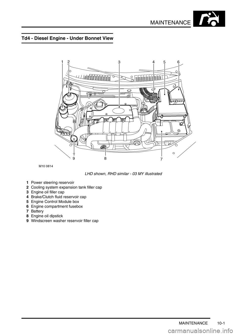
Td4 - Diesel Engine - Under Bonnet View
LHD shown, RHD similar - 03 MY illustrated
1Power steering reservoir
2Cooling system expansion tank filler cap
3Engine oil filler cap
4Brake/Clutch fluid reservoir cap
5Engine Control Module box
6Engine compartment fusebox
7Battery
8Engine oil dipstick
9Windscreen washer reservoir filler cap
Page 149 of 1007
MAINTENANCE
10-2 MAINTENANCE
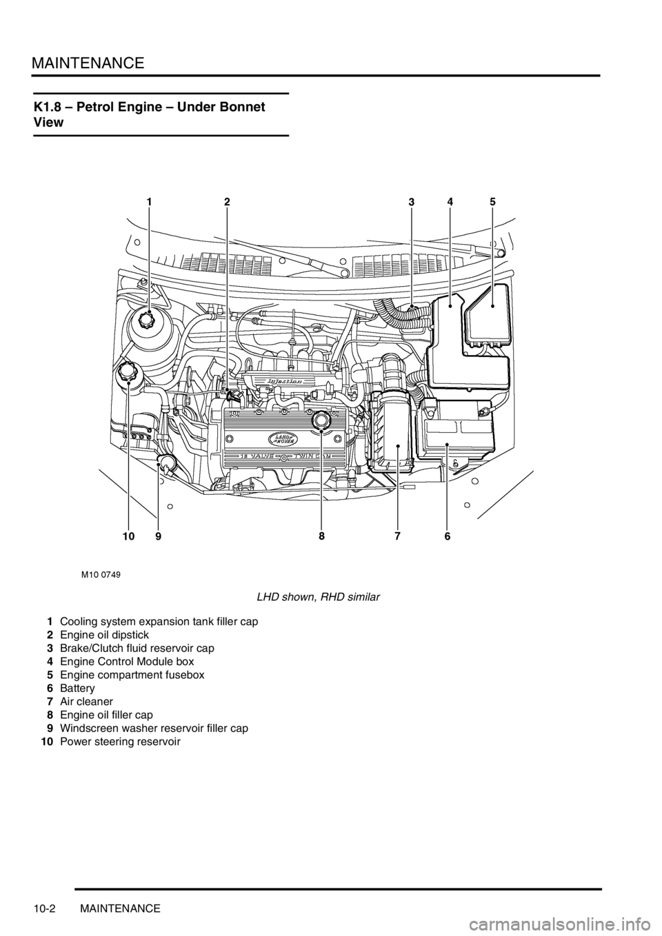
K1.8 – Petrol Engine – Under Bonnet
View
LHD shown, RHD similar
1Cooling system expansion tank filler cap
2Engine oil dipstick
3Brake/Clutch fluid reservoir cap
4Engine Control Module box
5Engine compartment fusebox
6Battery
7Air cleaner
8Engine oil filler cap
9Windscreen washer reservoir filler cap
10Power steering reservoir
Page 150 of 1007
MAINTENANCE
MAINTENANCE 10-3
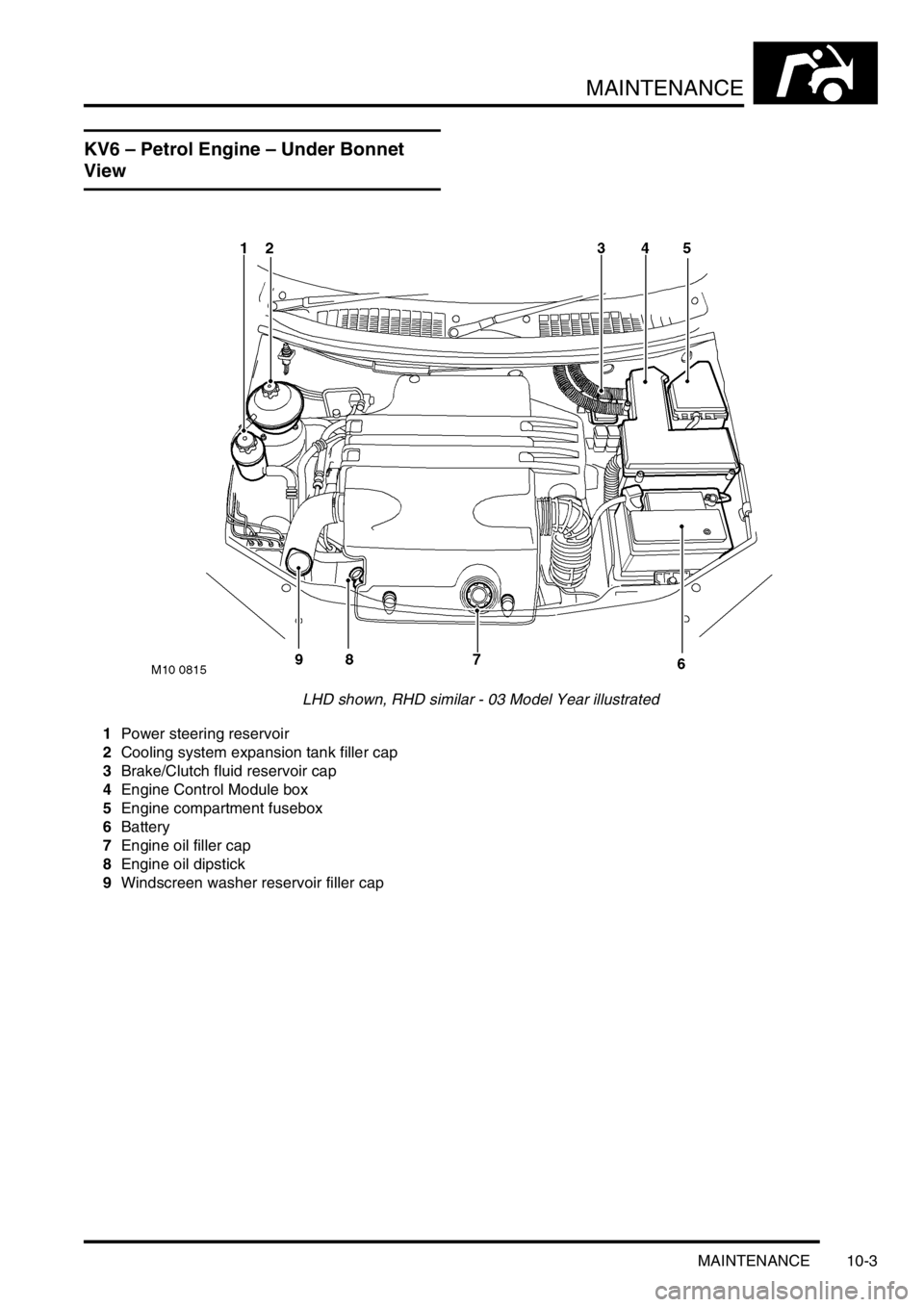
KV6 – Petrol Engine – Under Bonnet
View
LHD shown, RHD similar - 03 Model Year illustrated
1Power steering reservoir
2Cooling system expansion tank filler cap
3Brake/Clutch fluid reservoir cap
4Engine Control Module box
5Engine compartment fusebox
6Battery
7Engine oil filler cap
8Engine oil dipstick
9Windscreen washer reservoir filler cap
Page 203 of 1007
ENGINE - K SERIES KV6
12-3-26 REPAIRS
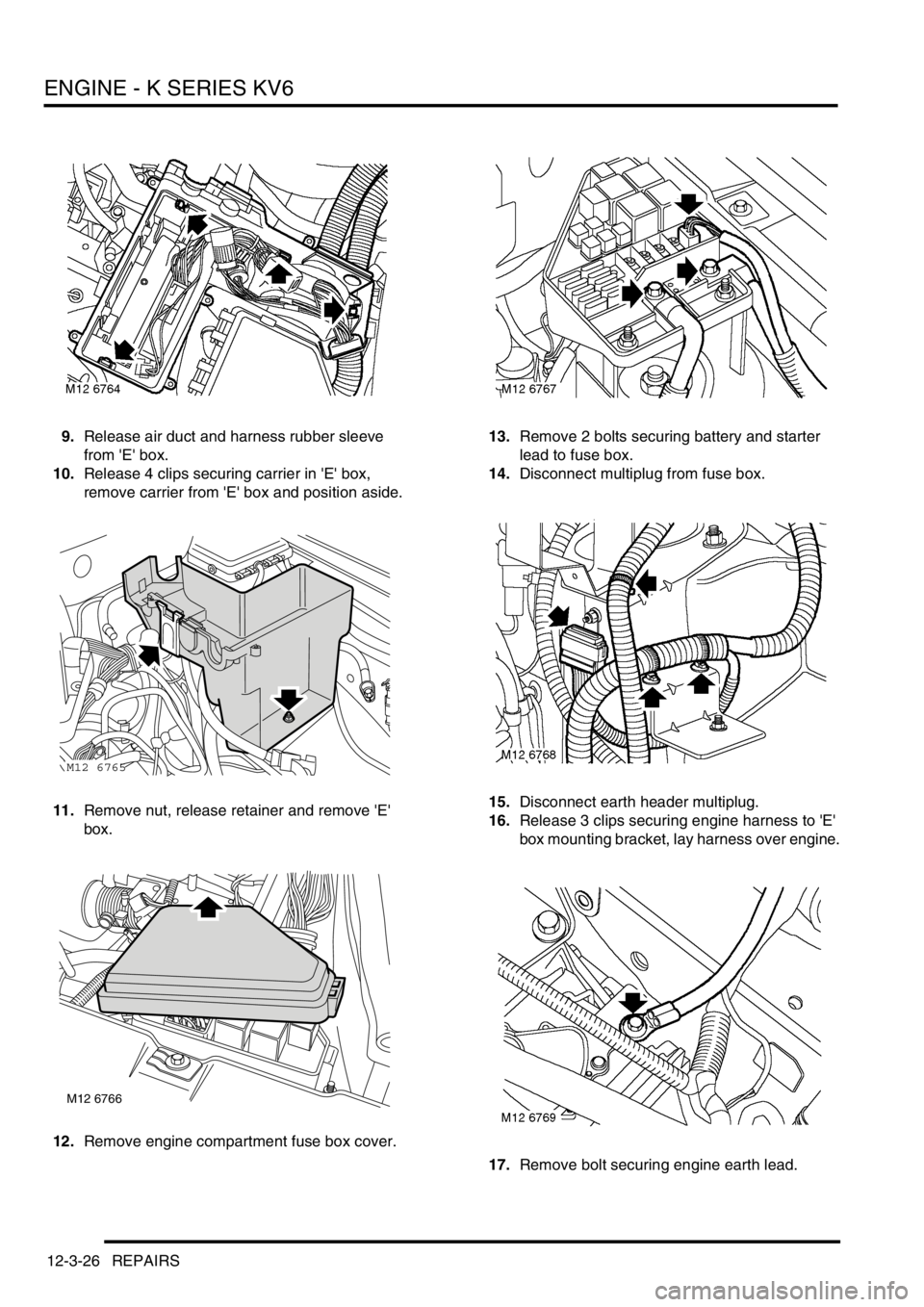
9.Release air duct and harness rubber sleeve
from 'E' box.
10.Release 4 clips securing carrier in 'E' box,
remove carrier from 'E' box and position aside.
11.Remove nut, release retainer and remove 'E'
box.
12.Remove engine compartment fuse box cover.13.Remove 2 bolts securing battery and starter
lead to fuse box.
14.Disconnect multiplug from fuse box.
15.Disconnect earth header multiplug.
16.Release 3 clips securing engine harness to 'E'
box mounting bracket, lay harness over engine.
17.Remove bolt securing engine earth lead.
M12 6765
M12 6766
Page 211 of 1007

ENGINE - K SERIES KV6
12-3-34 REPAIRS
38.With assistant depressing the brake pedal,
tighten front hub nuts to 400 Nm (295 lbf.ft).
39.Stake nut to shaft.
40.Fit front road wheels, fit and tighten nuts to 115
Nm (85 lbf.ft).
41.Lower vehicle on ramp.
42.Connect brake servo vacuum hose to inlet
manifold chamber.
43.Connect coolant hose to underside of
expansion tank and secure with clip.
44.Connect expansion tank hose to inlet manifold
and secure clip.
45.Connect top hose to radiator and secure with
clip. Position hose in bracket.
46.Connect heater feed and return hoses and
secure with clips.
47.Connect throttle inner cable to throttle cam and
secure outer cable in abutment bracket, if fitted.
48.Secure throttle cable in clips on harness
brackets, if fitted.
49.Adjust throttle cable, if fitted.
+ FUEL DELIVERY SYSTEM -
PETROL, ADJUSTMENTS, Throttle cable -
check and adjust - KV6.
50.Connect hose to purge control valve.
51.Connect fuel hose to fuel rail pipe, fit rubber
sleeve over hose connector.
52.Connect gearbox harness multiplugs and
secure multiplugs in mounting bracket clips.
53.Connect Lucar connector to starter solenoid.
54.Position earth lead to gearbox housing, fit and
tighten bolt to 25 Nm (18 lbf.ft).
55.Position engine harness to 'E' box mounting
bracket and secure with clips.
56.Connect earth header multiplug.
57.Connect multiplug to underbonnet fuse box.
58.Position battery and starter motor lead to
underbonnet fuse box, fit and tighten bolts to 8
Nm (6 lbf.ft).
59.Fit underbonnet fuse box cover.
60.Position 'E' box, secure in retaining clip, fit and
tighten nut to 9 Nm (7 lbf.ft).
61.Position carrier in 'E' box and secure with clips.
62.Position and secure air duct and harness
rubber sleeve in 'E' box.
63.Connect multiplugs securing main harness to
engine harness.
64.Position ECM harness and multiplug to 'E' box,
align harness clamp and secure screws to 'E'
box.
65.Fit engine ECM.
+ ENGINE MANAGEMENT SYSTEM -
SIEMENS, REPAIRS, Engine control module
(ECM) - Non NAS.
66.Fit battery carrier.
+ CHARGING AND STARTING,
REPAIRS, Carrier - battery.67.Fill cooling system.
+ COOLING SYSTEM - K SERIES KV6,
ADJUSTMENTS, Coolant - drain and refill.
68.Connect battery earth lead.
69.Fill gearbox with fluid.
+ AUTOMATIC GEARBOX - JATCO,
ADJUSTMENTS, Gearbox fluid - drain &
refill.
70.Fit engine acoustic cover.
+ ENGINE - K SERIES KV6, REPAIRS,
Cover - engine acoustic.
Page 213 of 1007

ENGINE - K SERIES KV6
12-3-36 REPAIRS
17.Rotate heated front screen relay anti-clockwise
and release it from 'E' box bracket.
18.Release 4 clips and remove carrier from 'E' box.
19.Remove nut, release retainer and remove 'E'
box.20.Remove engine compartment fuse box cover.
21.Remove 2 bolts securing battery and starter
lead to fuse box.
22.Disconnect multiplug from fuse box.
23.Disconnect earth header multiplug.
24.Release 3 clips securing engine harness to 'E'
box mounting bracket, lay harness over engine.
M12 6765
M12 6766